VPLL-3003 - Lens SONY - Free user manual and instructions
Find the device manual for free VPLL-3003 SONY in PDF.

User questions about VPLL-3003 SONY
0 question about this device. Answer the ones you know or ask your own.
Ask a new question about this device
Download the instructions for your Lens in PDF format for free! Find your manual VPLL-3003 - SONY and take your electronic device back in hand. On this page are published all the documents necessary for the use of your device. VPLL-3003 by SONY.
USER MANUAL VPLL-3003 SONY
Operating Instructions ____ GB
Mode d'emploi FR
Sony Corporation Printed in Japan
VPLL-3003
© 2015 Sony Corporation

日本語
natural_image
Diagram of a washing machine with a rotating component and fan (no text or symbols)調整する
調整フロー
natural_image
Simple line drawing of a monitor with a stand (no text or symbols)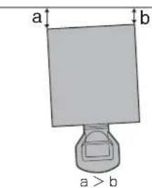
text_image
a b a > b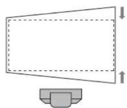
natural_image
Simple line drawing of a megaphone with dashed lines indicating height, no text or symbols present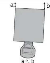
text_image
a b a < bnatural_image
Simple line drawing of a computer monitor with a base, no text or symbols present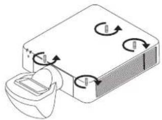
natural_image
Diagram of a device with rotating arrows and a container, no text or symbols present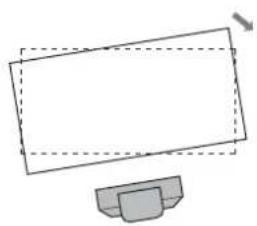
natural_image
Simple line drawing of a monitor with a base, no text or symbols present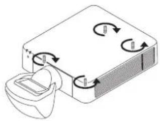
natural_image
Diagram of a device with rotating arrows indicating rotation or flow, no text or symbols presentnatural_image
Technical line drawing of a mechanical assembly with a tool and component (no text or symbols)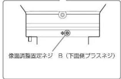
| L1 | L1 = 0.007053 × D - 0.016810 |
| L2 | L2 = 0.007048 × D + 0.101010 |
| L3 | L3 = 0.007048 × D - 0.154990 |
| L4 | L4 = 0.007048 × D - 0.669990 |
| L5 | L5 = 0.007048 × D - 0.363290 |
| H1 | H1 = 0.004712 × D - 0.072000 |
| H2 | H2 = 0.004712 × D - 0.021670 |
| H3 | H3 = 0.004712 × D + 0.099000 |
| H4 | H4 = 0.004712 × D + 0.161500 |
单位:m
Before operating the unit, please read this manual thoroughly and retain it for future reference.
This lens is designed for use with the Sony Projector. For details concerning compatible models, consult with qualified Sony personnel.
Attaching the lens may cause fire or injury to the person. Users should request qualified Sony representative to attach the lens.
For the customers in Europe, Australia and New Zealand
WARNING
This equipment is compliant with Class A of CISPR 32. In a residential environment this equipment may cause radio interference.
For the customers in Europe
This apparatus shall not be used in the residential area.
For the customers in the U.S.A. SONY LIMITED WARRANTY - Please visit http://www.sony.com/psa/warranty for important information and complete terms and conditions of Sony's limited warranty applicable to this product.
For the customers in Canada SONY LIMITED WARRANTY - Please visit http://www.sonybiz.ca/pro/lang/en/ca/article/resources-warranty-product-registration for important information and complete terms and conditions of Sony's limited warranty applicable to this product.
For the customers in Europe
Sony Professional Solutions Europe - Standard Warranty and Exceptions on Standard Warranty. Please visit http://www.pro.sony.eu/warranty for important information and complete terms and conditions.
For the customers in Korea SONY LIMITED WARRANTY - Please visit http://bpeng.sony.co.kr/handler/BPAS-Start for important information and complete terms and conditions of Sony's limited warranty applicable to this product.
Table of Contents
Precaution 21
Checking the Supplied Accessories 22
Attaching the Projection Lens 22
Attaching the feet 22
Removing the Projection Lens attached to the Projector 23
Attaching the Optical Filter 23
Removing the default image surface pins ..... 24
Attaching the Projection Lens VPLL-3003 ..... 24
Adjusting 25
Adjustment flow 25
Preparation 26
Setting and adjustment of the projector 26
Shift adjustment 28
Focus adjustment 28
Corner focus adjustment 28
Image surface adjustment 29
Confirmation method of the default position of the image surface 30
Removing the Projection Lens VPLL-3003 ..... 31
Others 32
Specifications 32
Projection Distance and Lens Shift Range ..... 32
Dimensions 34
Precaution
- Lenses can be scratched easily. When handling lenses, always place them gently on a stable, level surface in a horizontal position.
- Avoid touching the projection window and the lens surface.
- Do not place any object just in front of the projection window that may block the light during projection. If light is blocked, heat may damage the object or the lens of the unit (resulting in deformation, etc.). Use the picture muting function to suspend projection for a short while.
- Be careful not to drop the projection lens.
Cleaning the lens section
Wipe the projection window and the lens surface gently with a cleaning cloth or a spectacle cloth. Never use solvents such as alcohol, benzene, thinner, acid, alkaline or abrasive detergent, or a chemical cleaning cloth, which may damage the surface of the lens.
Note
The projection window is made of glass. If you forcibly push or hit it, it may break and cause an injury.
Cleaning the cabinet
- To remove dust from the cabinet, wipe gently with a soft cloth. If dust is persistent, wipe with a soft cloth slightly moistened with a diluted mild detergent solution.
- Never use any type of abrasive pad, alkaline/acid cleaner, scouring powder, or volatile solvent, such as alcohol, benzene, thinner or insecticide.
- Clean the unit with a cleaning cloth. Wiping with a dirty cloth may scratch the unit.
- Using such materials or maintaining prolonged contact with rubber or vinyl materials may result in damage to the cabinet material.
On condensation
If the room temperature where the projector is installed changes rapidly, or if the projector is moved suddenly from a cold to a warm place, condensation in the projector may occur. As the condensation may cause malfunction, be careful in adjusting temperature settings of the air conditioner. If condensation occurs, leave the projector turned on for about two hours before use.
Notes
• Always verify that the unit is operating properly before use. SONY WILL NOT BE LIABLE FOR DAMAGES OF ANY KIND INCLUDING, BUT NOT LIMITED TO, COMPENSATION OR REIMBURSEMENT ON ACCOUNT OF THE LOSS OF PRESENT OR PROSPECTIVE PROFITS DUE TO FAILURE OF THIS UNIT, EITHER DURING THE WARRANTY PERIOD OR AFTER EXPIRATION OF THE WARRANTY, OR FOR ANY OTHER REASON WHATSOEVER.
- SONY WILL NOT BE LIABLE FOR CLAIMS OF ANY KIND MADE BY USERS OF THIS UNIT OR MADE BY THIRD PARTIES.
- SONY WILL NOT BE LIABLE FOR THE TERMINATION OR DISCONTINUATION OF ANY SERVICES RELATED TO THIS UNIT THAT MAY RESULT DUE TO CIRCUMSTANCES OF ANY KIND.
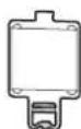
Checking the Supplied Accessories
Front foot (2)
Rear foot (2)
Optical filter (1)
Operating Instructions (1)
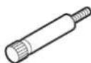
Attaching the Projection Lens
Attaching the feet
Notes
- When the projection lens VPLL-3003 is attached, attach the feet to the projector regardless of the installing condition. You can attach the ceiling mount unit even if the feet are attached.
- Attach the feet to the projector on a flat desk, etc.
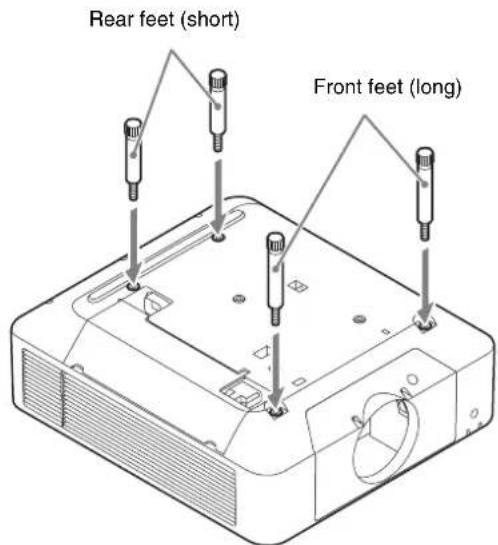
1 Reverse the projector.
2 Attach the 2 front feet (supplied) and the 2 rear feet (supplied) to the projector.
Attach the long feet to the front side and the short feet to the rear side.
text_image
Rear feet (short) Front feet (long)When using the ceiling mount unit, attach the base of the ceiling mount unit. For details, see the operating instructions of the ceiling mount unit.
3 Setting the projector on a flat surface.
Removing the Projection Lens attached to the Projector
1 Return the projection lens to the center position.
While the projector is turned on, press the LENS SHIFT button on the Remote Commander, then press the RESET button on it. The projection lens returns to the center position.
Note
The projection lens cannot be removed unless it has returned to the center position.
2 Turn off the projector, then unplug the AC power cord from the wall outlet.
Caution
When replacing the lens, your eyes may be damaged if a strong light accidentally gets into your eyes. Before replacing the lens, turn off the projector and then unplug the AC power cord.
3 While pressing and holding down the LENS RELEASE button, rotate the projection lens counterclockwise to pull out the lens straight.
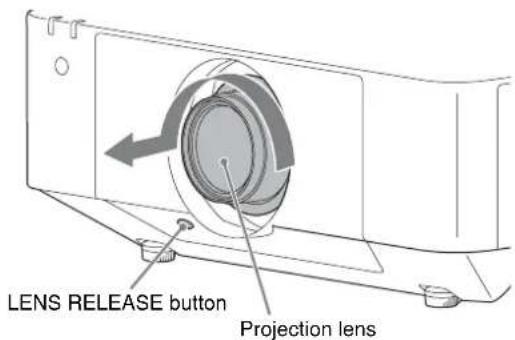
text_image
LENS RELEASE button Projection lensAttaching the Optical Filter
Note
When the projection lens VPLL-3003 is used, attach the optical filter. When the optical filter is not used, the image may be not displayed correctly.
1 Hold the lower part of the holder using a tweezer, pull it downwards to the front, and remove the glass attached to the projector.
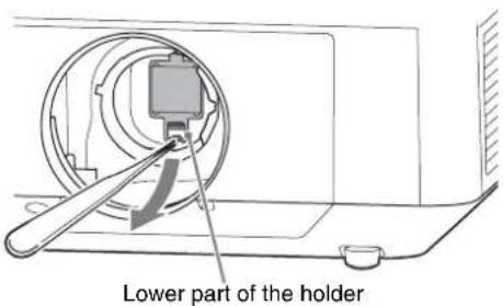
text_image
Lower part of the holder2 Attach the optical filter (supplied) using a tweezer.
Put the protrusion of the upper part of the optical filter into the prism base of the projector (1) and insert the lower part until it locks with a click (2).
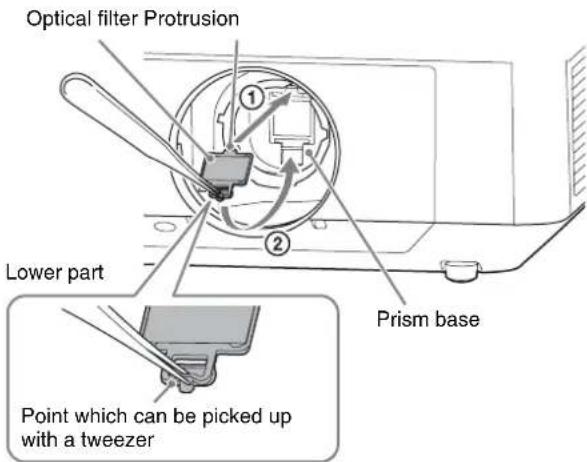
text_image
Optical filter Protrusion Lower part Prism base Point which can be picked up with a tweezerNote
If you do not operate the optical filter correctly during attaching or removing, it may be corrupted.
Tip
Cleaning the Optical Filter
- Before cleaning: Be sure that the power is turned off and the light source is turned off.
- Cleaning the optical filter:
Wipe the filter gently with a tissue paper which is moistened with potable water. Never use solvents such as alcohol, benzene, thinner, acid, alkaline or abrasive detergent, or a chemical cleaning cloth, which may damage the surface of the filter.
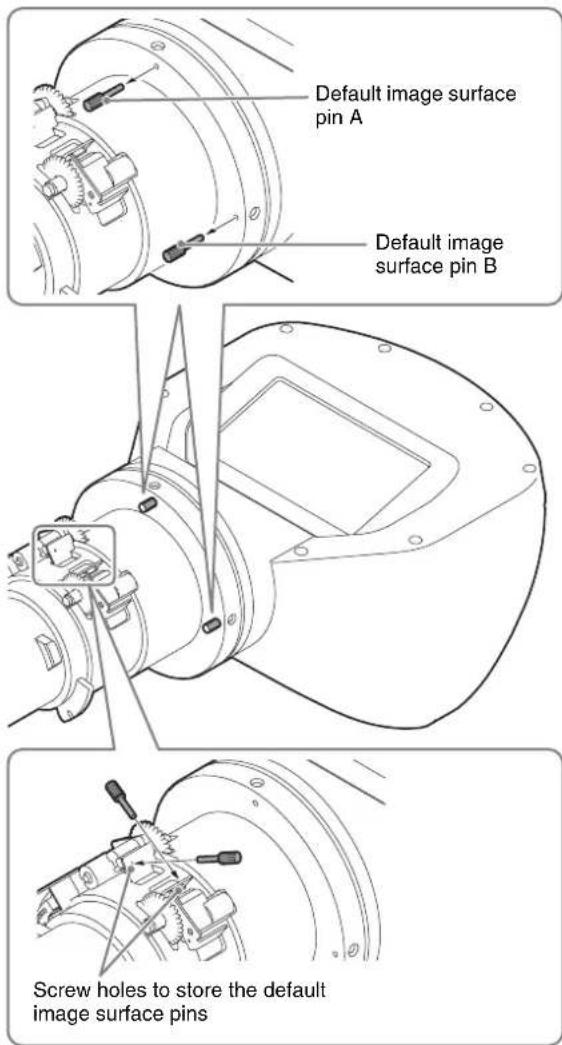
Removing the default image surface pins
Note
Make sure to remove the two default image surface pins before use. Otherwise, the projection lens may be damaged.
1
Pull the two default image surface pins on the ceiling side and on the side of the projection lens straight forward.
If the pins are too tight to pull out, use tools such as pliers.
You can store the removed pins by putting them into the screw holes near the removed positions. You can confirm the default position of the image surface using the default image surface pins. For details, see “Confirmation method of the default position of the image surface” (page 30).
text_image
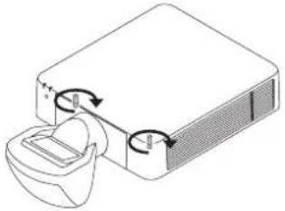
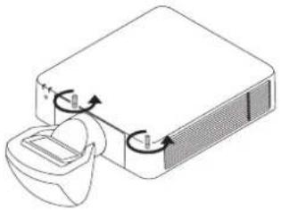
Default image surface pin A Default image surface pin B Screw holes to store the default image surface pinsAttaching the Projection Lens VPLL-3003
Notes
- When attaching the projection lens, put the projector on the floor.
- When attaching the projection lens, do not press the LENS RELEASE button.
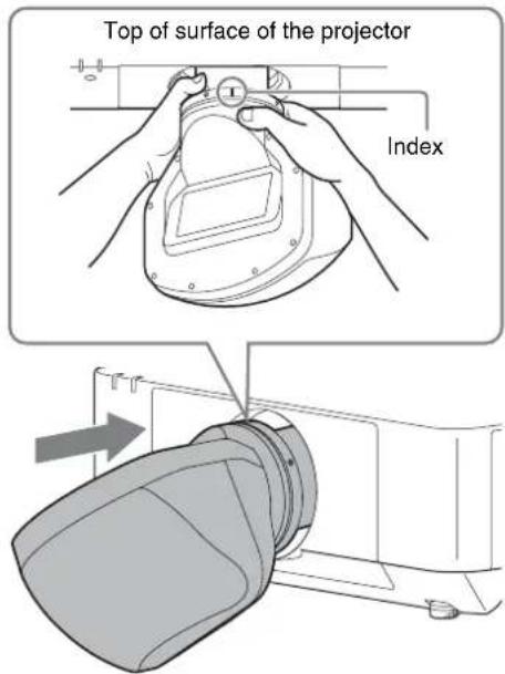
1
Fully insert the projection lens with the index on the lens facing toward the top surface of the projector.
Note
When attaching the projection lens, carry it grasped with both hands as shown in the illustration.
text_image
Top of surface of the projector Index2
Rotate the lens clockwise until it clicks.
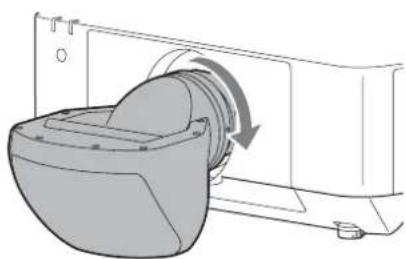
natural_image
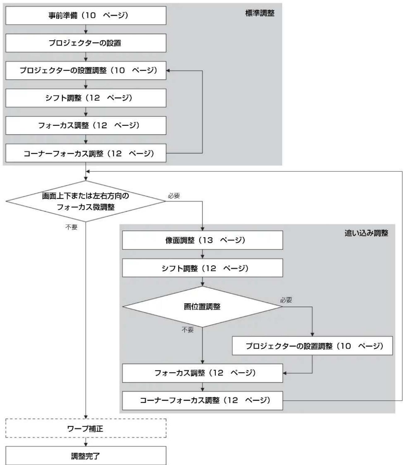
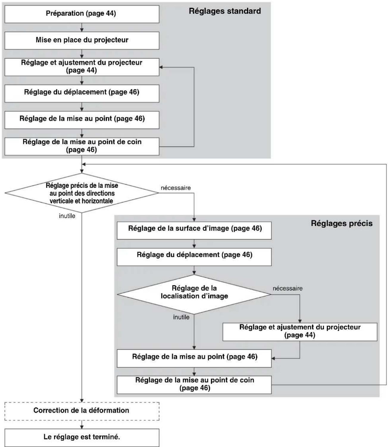
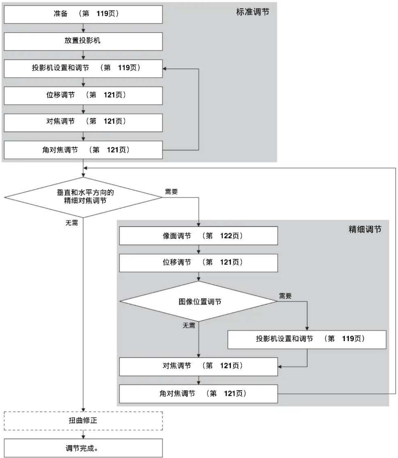
Diagram of a washing machine with a rotating component and fan mechanism (no text or symbols)Adjusting
Adjustment flow
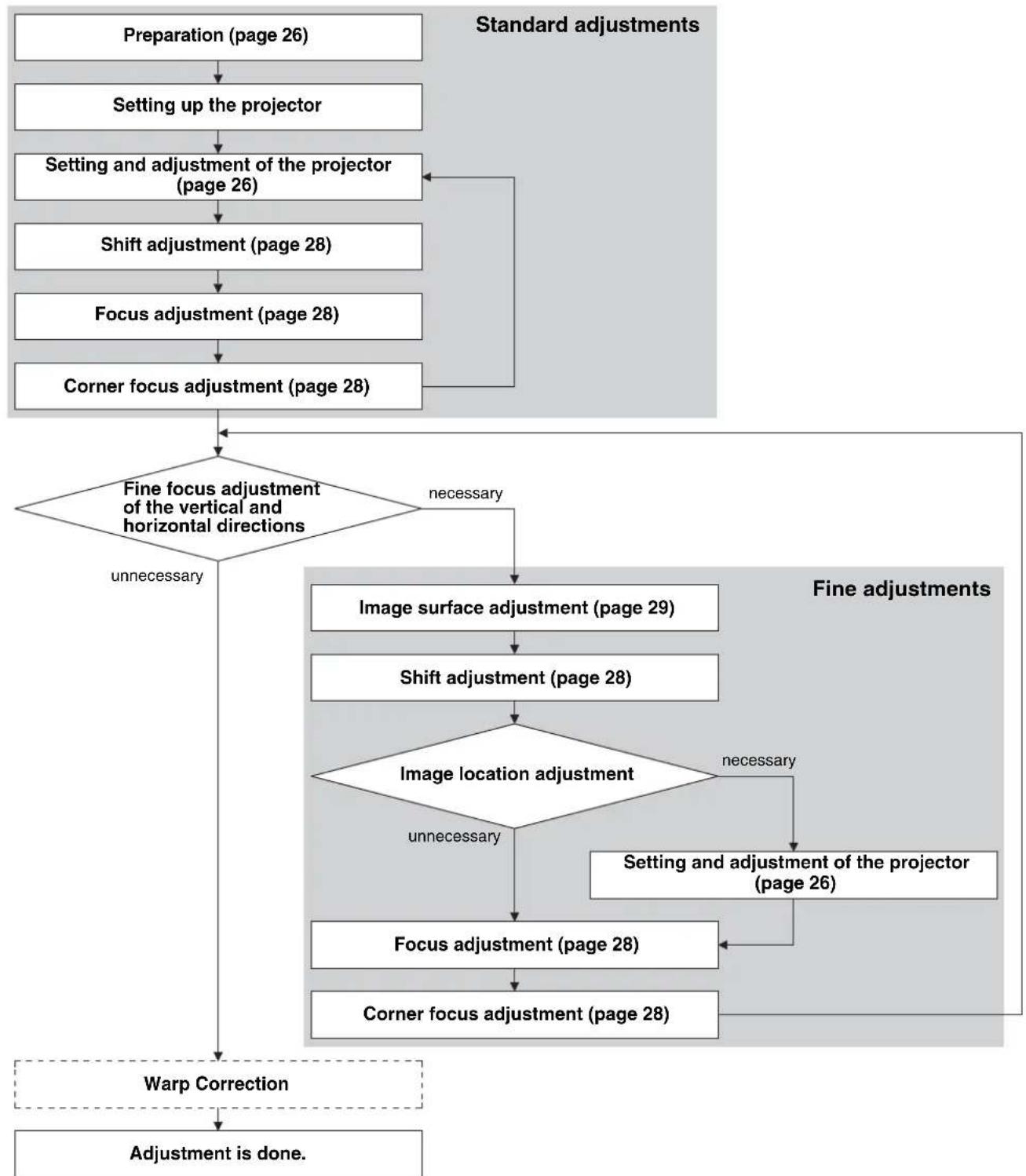
flowchart
graph TD
    A["Preparation (page 26)"] --> B["Setting up the projector"]
    B --> C["Setting and adjustment of the projector (page 26)"]
    C --> D["Shift adjustment (page 28)"]
    D --> E["Focus adjustment (page 28)"]
    E --> F["Corner focus adjustment (page 28)"]
    F --> G{Fine focus adjustment of the vertical and horizontal directions}
    G -->|unnecessary| H["Image surface adjustment (page 29)"]
    G -->|necessary| I["Image location adjustment"]
    H --> J["Shift adjustment (page 28)"]
    J --> K{Image location adjustment}
    K -->|unnecessary| L["Focus adjustment (page 28)"]
    K -->|necessary| M["Setting and adjustment of the projector (page 26)"]
    L --> N["Corner focus adjustment (page 28)"]
    M --> O["Warp Correction"]
    N --> O
    O --> P["Adjustment is done."]
    style A fill:#f9f,stroke:#333
    style P fill:#f9f,stroke:#333
For the warp correction, see the operating instruction of the projector.
Preparation
1 Turn on the projector.
The projection lens moves automatically to the initial position.
Note
When the projection lens moves to the initial position, make sure that the lens does not strike anything.
2 Move the shift's vertical direction close to the center.
Press the SHIFT button on the Remote Commander or the control panel of the projector, and adjust with ↑/↓.
Notes
- Set the image inversion of the projector so that the top and bottom, left and right of the image is projected correctly depending on the projection environment.
- The initial shift position of the projection lens is the top shift position of the suspended condition and the bottom shift position of the floor position condition. Before setting the projector, the shift should be near the center for the fine adjustment of the vertical direction.
Setting and adjustment of the projector
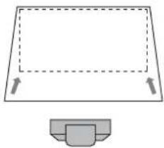
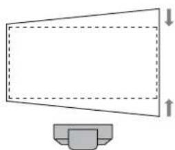
1 Check if the upper side and lower side of the picture are parallel.
If not, install the projector in a position parallel to the projection surface (a=b).
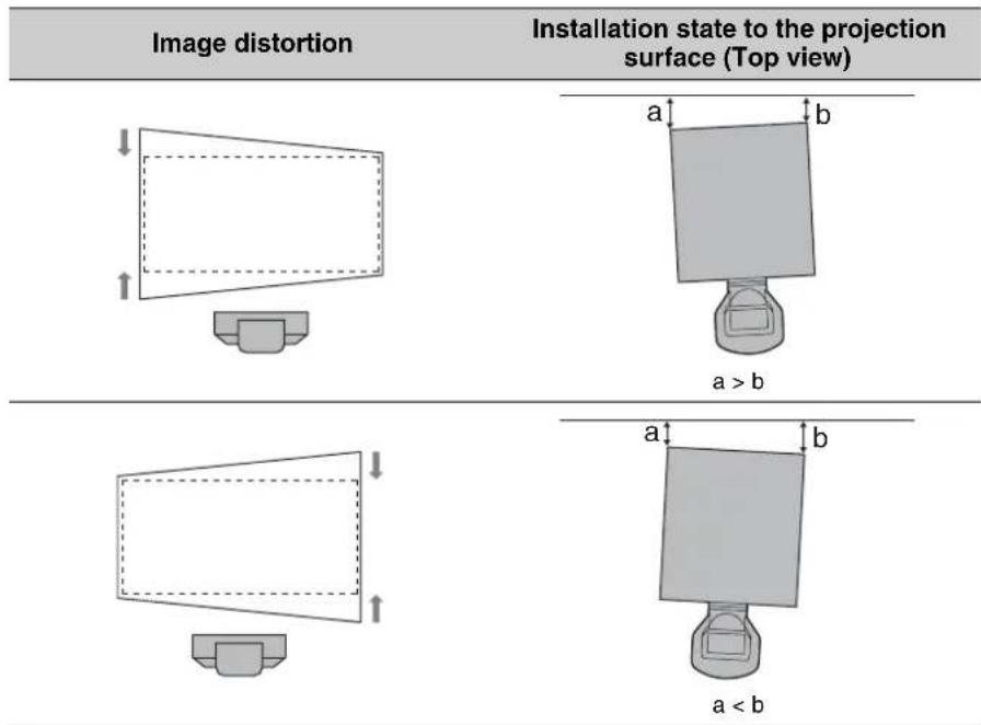
text_image
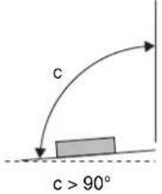
Image distortion Installation state to the projection surface (Top view) ↓ ↑ a b a > b ↓ ↑ a b a < b2 Check if the lower side of the picture is horizontal.
When the projector is not positioned horizontally, adjust the ceiling mount unit or feet (adjustable) so that the projector is positioned horizontally.
For details concerning the adjusting of the ceiling mount unit, see the operating instructions of the ceiling mount unit.
For details concerning feet adjustment, see page 28.
Image distortion Feet adjustment

natural_image
Simple line drawing of a computer monitor with a base, no text or symbols present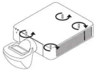
natural_image
Diagram of a device with rotating arrows and a container, no text or symbols present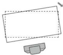
natural_image
Simple line drawing of a computer monitor with a base (no text or symbols)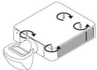
natural_image
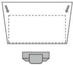
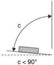
Diagram of a device with rotating arrows and a container, no text or symbols present3 Check if the left side and right side of the picture are vertical.
When the projector is not positioned vertically, adjust the ceiling mount unit or feet (adjustable) so that the projector is positioned vertically.
For details concerning the adjusting of the ceiling mount unit, see the operating instructions of the ceiling mount unit.
For details concerning feet adjustment, see page 28.
| Image distortion Installation state to the projection surface (Side view) | Feet adjustment | |
 |  |  |
 |  |  |
Adjusting the feet
You can adjust the height by using the four feet at the bottom of the projector.
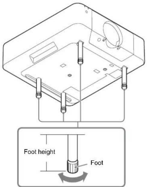
text_image
Foot height Foot1 Turn the feet bottom to the right when viewed from the projector top and loosen it.
Shift adjustment
1 Press the PATTERN button on the Remote Commander.
2 Press the SHIFT button on the Remote Commander or the control panel of the projector, and adjust with /// .
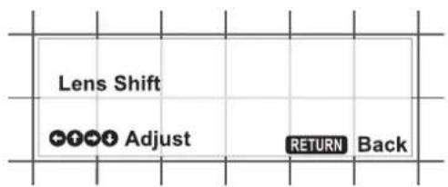
text_image
Lens Shift Adjust RETURN BackFocus adjustment
1 Adjust the focus by watching the screen center.
Press the FOCUS button on the Remote Commander or the control panel of the projector once, and adjust with /// .
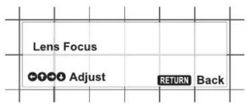
text_image
Lens Focus Adjust RETURN BackCorner focus adjustment
Normal focus adjustment and corner focus adjustment are also necessary when the projection lens VPLL-3003 is attached.
1 Adjust the focus while watching the corner of the screen.
Press the FOCUS button on the Remote Commander or the control panel of the projector twice, and adjust with /// .
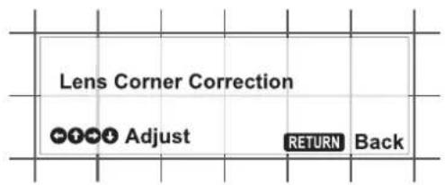
text_image
Lens Corner Correction Adjust RETURN BackImage surface adjustment
Normally, perform the procedures for the standard adjustments (page 26 to 28). In addition, when the fine adjustments are necessary, perform the procedures below.
When the image surface adjustment screws are turned, the focus on the projection surface can be adjusted by adjusting the inclinations of top and bottom or left and right of the image surface. To enhance the accuracy of the image surface adjustment, repeat the adjustment several times.
Adjustment of the vertical image surface
Image surface adjustment screw A (plus screw on the ceiling side)
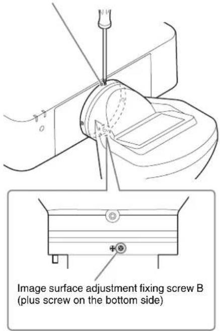
text_image
Image surface adjustment fixing screw B (plus screw on the bottom side)1 Loosen the image surface adjustment fixing screw B by turning it to the left several times.
2 Adjust the focus of the projection lens at the projected surface near the projector using the button on the remote control or the projector.
3 Check the projected surface further from the projector, and confirm if the focus position is in front of the projected surface or at the far back of the projected surface.
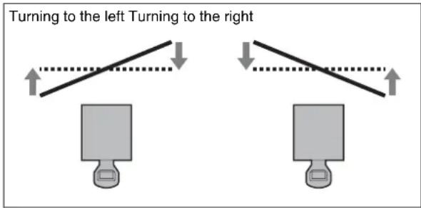
4 Adjust the position of the image surface to adjust the focus further from the projector. When the image surface confirmed in step 3 is in front of the
projected surface, turn the image surface adjustment screw A to the left. When the image surface confirmed in step 3 is at the far back of the projected surface, turn the image surface adjustment screw A to the right.
Example of adjustment using the image surface adjustment screw A (the plus screw on the ceiling side)

text_image
Turning to the left Turning to the right The projected surface near the projector The projected surface further from the projector.... Projected surface (screen) — Image surface
5 Adjust the position of the image surface by repeating steps 2 to 4 so that the focus can be adjusted in all positions.
6 When the adjustment is finished, turn the image surface adjustment fixing screw B to the right and tighten the screw until it is fixed.
Adjustment of the horizontal image surface
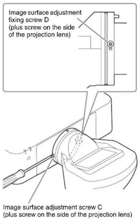
text_image
Image surface adjustment fixing screw D (plus screw on the side of the projection lens) Image surface adjustment screw C (plus screw on the side of the projection lens)1 Loosen the image surface adjustment fixing screw D by turning it to the left several times.
2 Adjust the focus of the projection lens at the left of the projected surface (or at the projected surface near the image surface adjustment screw C) using the button on the remote control or the projector.
3 Check the right of the projected surface (or at the projected surface further from the image surface adjustment screw C), and confirm if the focus position is in front of the projected surface or at the far back of the projected surface.
4 Adjust the position of the image surface to adjust the focus on the right of the projected surface. When the image surface confirmed in step 3 is in front of the projected surface, turn the image surface adjustment screw C to the right. When the image surface confirmed in step 3 is at the far back of the projected surface, turn the image surface adjustment screw C to the left.
Example of adjustment using the image surface adjustment screw C (the plus screw on the side of the projection lens)
text_image
Turning to the left Turning to the right.... Projected surface (screen) — Image surface
5 Adjust the position of the image surface by repeating steps 2 to 4 so that the focus can be adjusted in all positions.
6 When the adjustment is finished, turn the image surface adjustment fixing screw D to the right and tighten the screw until it is fixed.
Confirmation method of the default position of the image surface
For the positions of the default image surface pin A and B, see the illustration on page 24. For the positions of the image surface adjustment screw A and C, and image surface adjustment fixing screw B and D, see the illustrations on page 29.
Confirmation method of the default position of the vertical image surface
1 Loosen the image surface adjustment fixing screw B by turning it to the left several times.
2 Turn the image surface adjustment screw A to the right until the default image surface pin A of the ceiling side can be inserted.
3 Insert the default image surface pin A of the ceiling side straightly as far as it will go.
If the pin is not inserted fully, repeat steps 1 and 2.
4 Turn the image surface adjustment screw A to the left until the default image surface pin A is fixed firmly.
You can confirm the default position of the image surface.
Confirmation method of the default position of the horizontal image surface
1 Loosen the image surface adjustment fixing screw D by turning it to the left several times.
2 Turn the image surface adjustment screw C to the right until the default image surface pin B of the side of the projection lens can be inserted.
3 Insert the default image surface pin B of the side of the projection lens straightly as far as it will go.
If the pin is not inserted fully, repeat steps 1 and 2.
4 Turn the image surface adjustment screw C to the left until the default image surface pin B is fixed firmly.
You can confirm the default position of the image surface.
Notes
- If the image surface adjustment fixing screws are loosen too much, the screws may fall and be lost.
- Remove the default image surface pins before use. For details, see “Removing the default image surface pins” (page 24).
Removing the Projection Lens VPLL-3003
- The projection lens cannot be removed unless it has returned to the center position.
- Do not remove the AC power cord while the power is shutting down because the lens moves to the center position just before the power is shut down.
1 Return the projection lens to the center position.
While the projector is turned on, press the LENS SHIFT button on the Remote Commander, then press the RESET button on it. The projection lens returns to the center position.
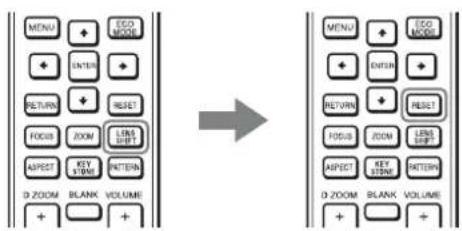
text_image
MENU + ECO MODE ENTER + RETURN + RESET FOCUS ZOOM LINK LIFT ASPECT KEY LIFERS PATTERN D ZOOM BLANK VOLUME + + → MENU + ECO MODE ENTER + RETURN + RESET FOCUS ZOOM LINK LIFT ASPECT KEY LIFERS PATTERN D ZOOM BLANK VOLUME + +2 While pressing and holding down the LENS RELEASE button, rotate the projection lens counterclockwise (①) to pull out the lens straight (②).
text_image
Top of surface of the projector Index LENS RELEASE buttonNote
When removing the projection lens, carry it grasped with both hands as shown in the illustration.
Note
When removing the projection lens, put the projector down on the floor.
Others
Specifications
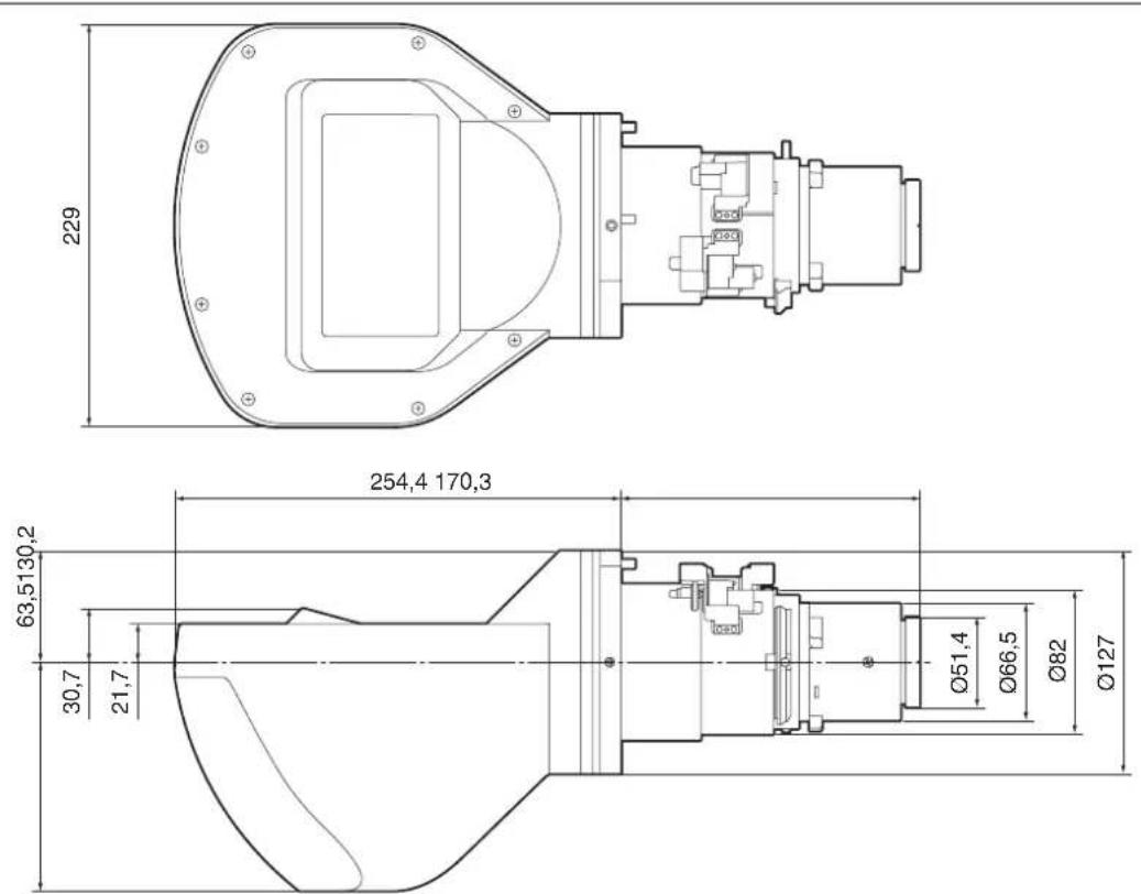
Maximum dimensions (W/H/D) Approx. 229 mm × 193.7 mm × 424.7 mm
$$ (9 ^ {1} / _ {3 2} \text { inches } \times 7 ^ {5} / _ {8} \text { inches } \times 1 6 ^ {2 3} / _ {3 2} \text { inches }) $$
Mass Approx. 2.9 kg (6.4 lb)
Note
The external form measurement and the mass are approximate values.
Design and specifications are subject to change without notice.
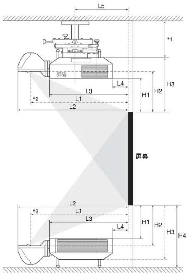
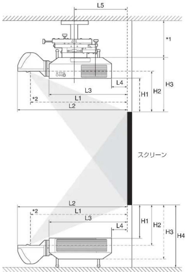
Projection Distance and Lens Shift Range
Projection distance
| Projection image size | L1 L2 | L3 L4 L5 | H1 H2 H3 | H4 | ||||||
| Diagonal Width × Height | ||||||||||
| 80" (2.03 m) | 1.72 × 1.08 (67^7/_8 × 42^3/_8) | 0.55 (21^1/_2) | 0.66 (26^1/_8) | 0.41 (16^1/_8) | -0.11 (-4^1/_8) | 0.20 (7^7/_8) | 0.30(12) | 0.36(14) | 0.48 (18^3/_4) | 0.54 (21^1/_4) |
| 100" (2.54 m) | 2.15 × 1.35 (84^3/_4 × 53) | 0.69 (27^1/_8) | 0.81 (31^3/_4) | 0.55 (21^5/_8) | 0.03 (1^3/_8) | 0.34 (13^1/_2) | 0.40 (15^3/_4) | 0.45 (17^3/_4) | 0.57 (22^1/_2) | 0.63 (24^7/_8) |
| 120" (3.05 m) | 2.58 × 1.62 (101^3/_4 × 63^5/_8) | 0.83 (32^5/_8) | 0.95 (37^1/_4) | 0.69 (27^1/_4) | 0.18 (6^7/_8) | 0.48(19) | 0.49 (19^3/_8) | 0.54 (21^3/_8) | 0.66 (26^1/_8) | 0.73 (28^5/_8) |
| 150" (3.81 m) | 3.23 × 2.02 (127^1/_4 × 79^1/_2) | 1.04(41) | 1.16 (45^5/_8) | 0.90 (35^1/_2) | 0.39 (15^1/_4) | 0.69 (27^3/_8) | 0.63(25) | 0.69(27) | 0.81 (31^3/_4) | 0.87 (34^1/_8) |
| 200" (5.08 m) | 4.31 × 2.69 (169^5/_8 × 106) | 1.39 (54^7/_8) | 1.51 (59^1/_2) | 1.25 (49^3/_8) | 0.74 (29^1/_8) | 1.05 (41^1/_4) | 0.87 (34^1/_4) | 0.92 (36^1/_4) | 1.04(41) | 1.10 (43^1/_2) |
| 300" (7.62 m) | 6.46 × 4.04 (254^3/_8 × 159) | 2.10 (82^5/_8) | 2.22 (87^1/_4) | 1.96 (77^1/_8) | 1.44 (56^7/_8) | 1.75(69) | 1.34 (52^7/_8) | 1.39 (54^3/_4) | 1.51 (59^1/_2) | 1.58(62) |
Unit: m (inches)
Projection distance formula
D: Projected image size (Diagonal)
| L1 | L1 = 0.007053 × D - 0.016810 ( L1 = 0.277674 × D - 0.661950) |
| L2 | L2 = 0.007048 × D + 0.101010 ( L2 = 0.277471 × D + 3.976810) |
| L3 | L3 = 0.007048 × D - 0.154990 ( L3 = 0.277471 × D - 6.101930) |
| L4 | L4 = 0.007048 × D - 0.669990 ( L4 = 0.277471 × D - 26.377520) |
| L5 | L5 = 0.007048 × D - 0.363290 ( L5 = 0.277471 × D - 14.302710) |
| H1 | H1 = 0.004712 × D - 0.072000 ( H1 = 0.185500 × D - 2.834650) |
| H2 | H2 = 0.004712 × D - 0.021670 ( H2 = 0.185500 × D - 0.853150) |
| H3 | H3 = 0.004712 × D + 0.099000 ( H3 = 0.185500 × D + 3.897640) |
| H4 | H4 = 0.004712 × D + 0.161500 ( H4 = 0.185500 × D + 6.358270) |
Unit: m (inches)
text_image
L5 *1 L3 L4 H3 *2 L1 H1 H2 L2 Screen L2 L1 L3 H1 H2 H3 H4 L4*1 See the operating instructions of the ceiling mount unit.
*2 Center of the cover glass
Lens shift range
text_image
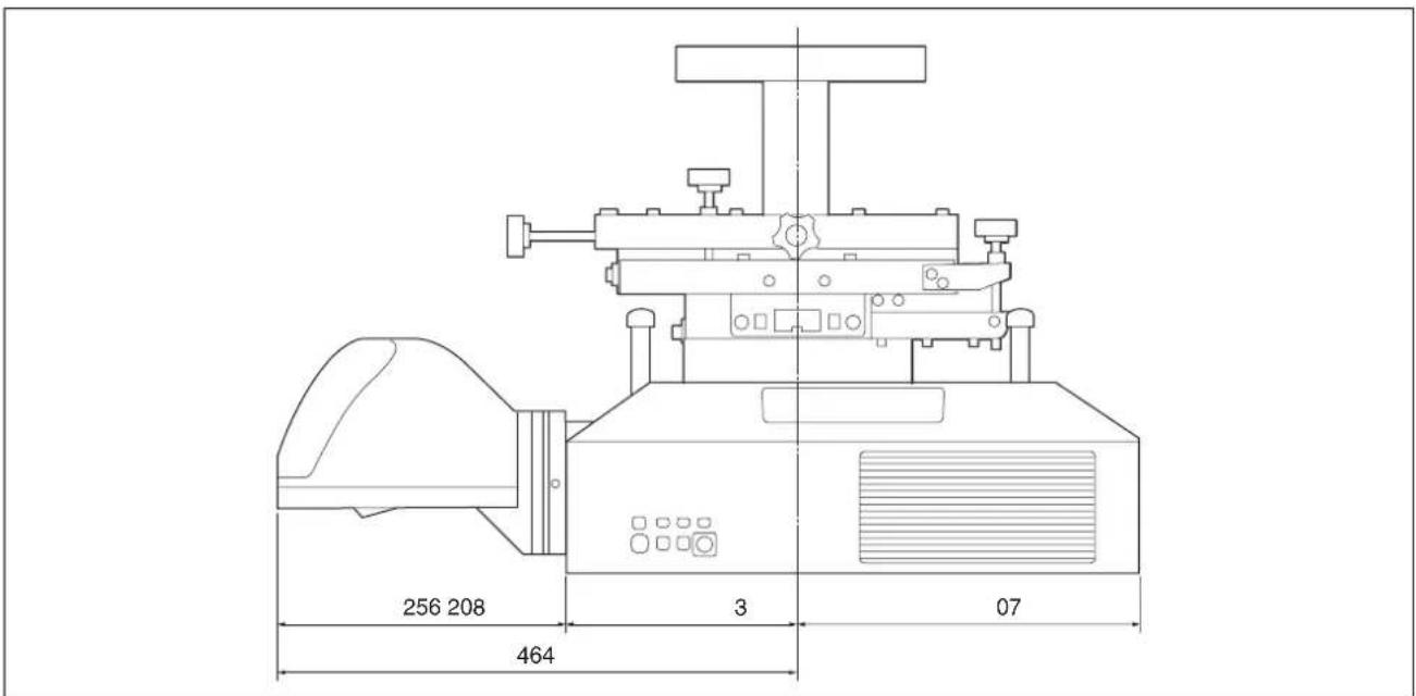
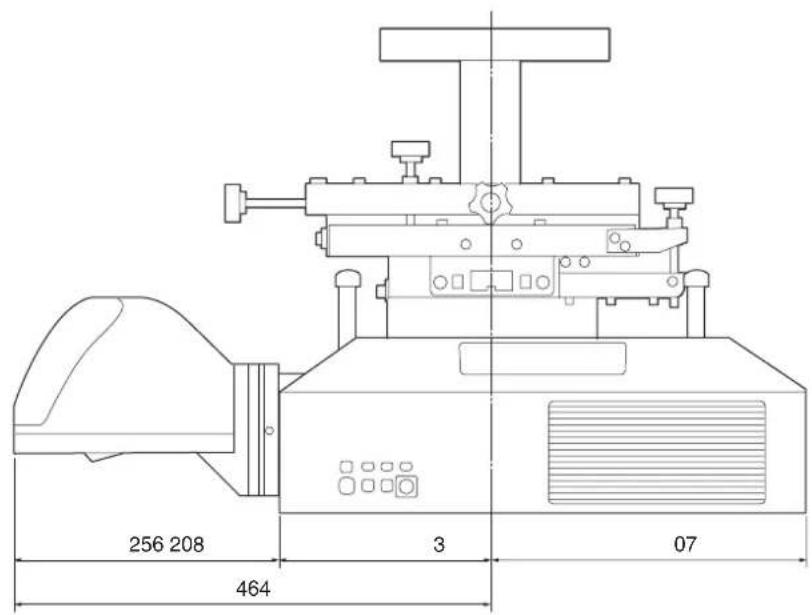
Projected image Center of the lens 5% V 5% 5% H 5%Dimensions
text_image
229 (9 1/32) 254.4 (10 1/32) 170.3 (6 23/32) 63.5 (2 1/2) 30.7 (1 7/32) 21.7 (27 1/32) 130.2 (5 1/8) Ø51.4 (2 1/32) Ø66.5 (2 5/8) Ø82 (3 7/32) Ø127 (5)Unit: mm (inches)
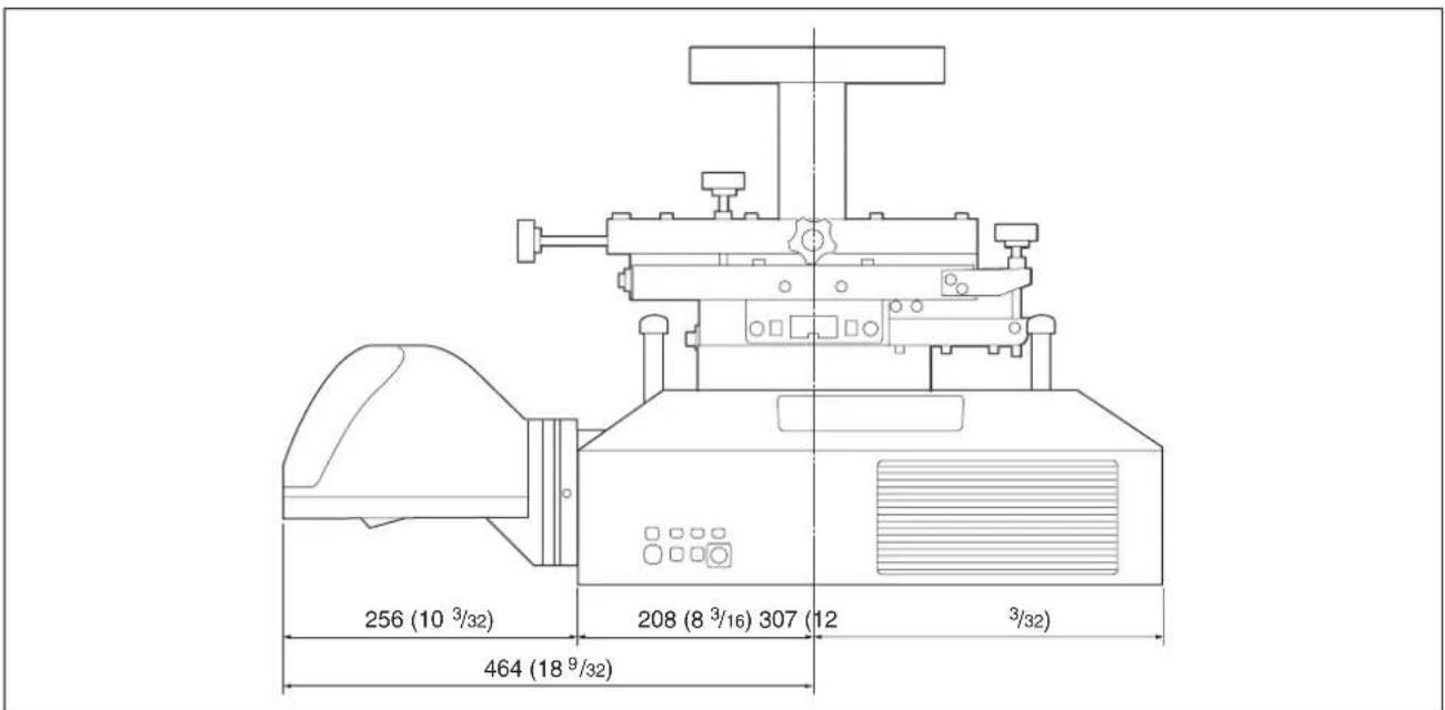
text_image
256 (10 3/32) 208 (8 3/16) 307 (12 3/32) 464 (18 9/32)Unit: mm (inches)
Note
For the projector that uses lamps, a space is required behind the projector or you cannot change the lamp.
Français
natural_image
Diagram of a washing machine with a rotating button and handle (no text or symbols)Réglage
Flux de réglage
natural_image
Simple line drawing of a computer monitor with a base, no text or symbols present
natural_image
Diagram of a device with rotating arrows and a magnified view of a component (no text or symbols)
natural_image
Simple line drawing of a computer monitor with a base, no text or symbols present
natural_image
Diagram of a device with rotating arrows indicating rotation, no text or symbols presentnatural_image
Technical line drawing of a mechanical assembly with no visible text or symbolsnatural_image
Diagram of a washing machine with a rotating button and cable (no text or symbols)Ajuste
natural_image
Technical line drawing of a mechanical component with no visible text or symbolsnatural_image
Two identical diagrams showing a diagonal line with upward arrows and a base with a lock icon, no text or symbols present.text_image
L5 *1 L3 L4 H1 H2 H3 *2 L1 L2 Pantalla L2 L1 L3 L4 H1 H2 H3 H4text_image
5% V 5% 5% H 5%Dimensiones

Unidad: mm
text_image
256 208 3 07 464Unidad: mm
Nota
natural_image
Diagram of a washing machine with a rotating component and fan (no text or symbols)Einstellen
natural_image
Simple line drawing of a computer monitor with a base, no text or symbols present
natural_image
Diagram of a device with rotating arrows and a magnified view of a component (no text or symbols)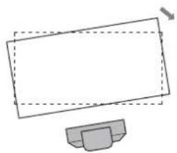
natural_image
Simple line drawing of a computer monitor with a base, no text or symbols present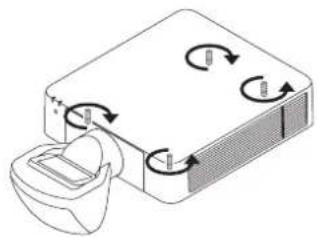
natural_image
Diagram of a device with rotating arrows indicating rotation, no text or symbols presentnatural_image
Simple diagram of a container with arrows indicating direction, no text or symbols present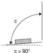
text_image
c c > 90°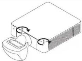
natural_image
Diagram of a device with a speaker and two circular components, no text or symbols present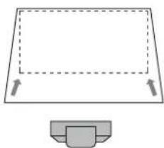
natural_image
Simple line drawing of a rectangular frame with dashed lines and arrows, plus a small gray container below (no text or symbols)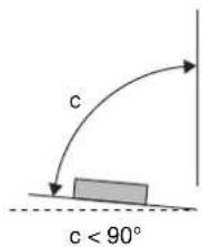
text_image
c c < 90°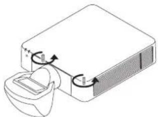
natural_image
Diagram of a device with a container and directional arrows indicating flow or movement (no text or symbols)Einstellen der Füße
natural_image
Technical line drawing of a mechanical assembly with no visible text or symbols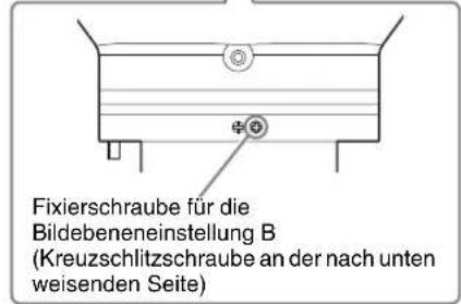
text_image
5% V 5% 5% H 5%Abmessungen
Einheit: mm
text_image
256 208 464 3 07Einheit: mm
Hinweis
natural_image
Diagram of a washing machine with a rotating button and cable (no text or symbols)Regolazione
natural_image
Technical line drawing of a mechanical assembly with no visible text or symbolstext_image
L5 *1 L4 H3 L3 H1 H2 L1 L2 *2 Schermo L2 L1 L3 H1 H2 H3 H4 L4natural_image
Technical line drawing of a mechanical component with no visible text or symbols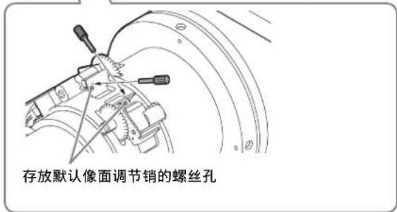
text_image
存放默认像面调节销的螺丝孔安装投影镜头 VPLL-3003
注意
natural_image
Diagram of a mechanical device with a rotating component and directional arrows indicating motion (no text or symbols)调节
调节流程
natural_image
Simple line drawing of a monitor with a stand (no text or symbols)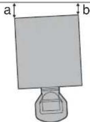
text_image
a ba > b
natural_image
Simple line drawing of a monitor with a base, no text or symbols present
natural_image
Simple diagram of a rectangular object with labeled dimensions 'a' and 'b' (no text or symbols on the object itself)a < b
2 检查图像的下侧是否水平。
natural_image
Simple line drawing of a computer monitor with a base, no text or symbols present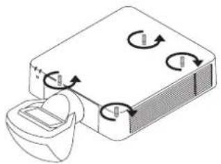
natural_image
Diagram of a device with rotating arrows indicating rotation, no text or symbols present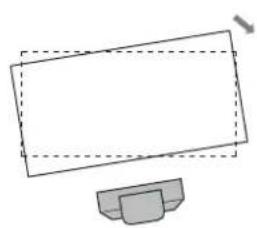
natural_image
Simple line drawing of a computer monitor with a base (no text or symbols)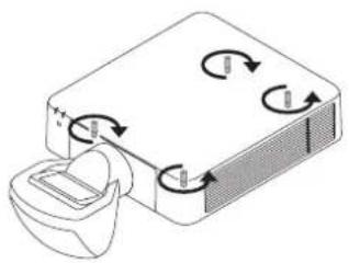
natural_image
Diagram of a device with rotating arrows indicating rotation, no text or symbols present3 检查图像的左侧和右侧是否垂直。
natural_image
Simple line drawing of a rectangular frame with dashed lines and arrows, no text or symbols present.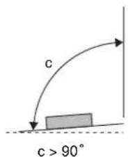
text_image
c c > 90°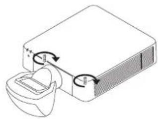
natural_image
Diagram of a device with a container and directional arrows indicating rotation or movement (no text or symbols)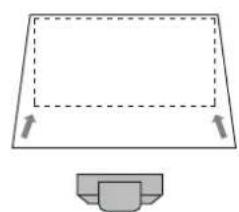
natural_image
Simple line drawing of a rectangular frame with dashed lines and arrows indicating direction, plus a small gray container below (no text or symbols)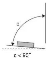
text_image
c c < 90°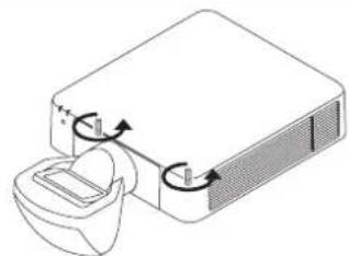
natural_image
Diagram of a device with a lid and internal components, showing rotational arrows (no text or symbols)调节支脚
可以使用投影机底部的四个支脚调节高度。
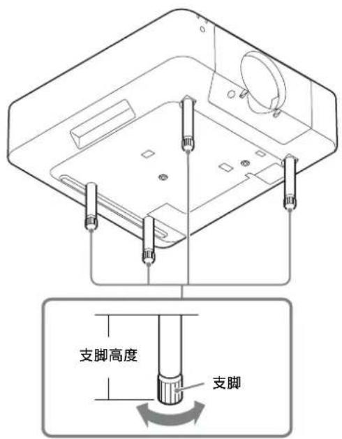
text_image
支脚高度 支脚| L1 L1 = 0.007053 × D - 0.016810 |
| L2 L2 = 0.007048 × D + 0.101010 |
| L3 L3 = 0.007048 × D - 0.154990 |
| L4 L4 = 0.007048 × D - 0.669990 |
| L5 L5 = 0.007048 × D - 0.363290 |
| H1 H1 = 0.004712 × D - 0.072000 |
| H2 H2 = 0.004712 × D - 0.021670 |
| H3 H3 = 0.004712 × D + 0.099000 |
| H4 H4 = 0.004712 × D + 0.161500 |
单位:m