
CLBA123 - Screwdriver Cleco - Free user manual and instructions
Find the device manual for free CLBA123 Cleco in PDF.

| Product type | Cordless angle screwdriver |
| Brand | Cleco |
| Model | CLBA123 |
| Dimensions (L x W x H) | 452.5 x 76 x 12.5 mm (without battery) |
| Weight | 1.46 kg (without battery) |
| Power supply | 18 V lithium-ion battery (compatible with Milwaukee) |
| Recommended battery capacity | 2.0 Ah or 5.0 Ah |
| Torque range | 3.3 – 12 Nm |
| Rotation speed | 65 – 650 rpm |
| Output | 3/8" |
| Connectivity | WLAN and Bluetooth 4.0 |
| Main functions | Screw tightening/loosening, work light, status indicator, programming via CellClutch software |
| Safety | CE, UKCA, UL compliance, protection class III, protection against inadvertent starts |
| Maintenance | Daily visual inspection, maintenance every 250,000 cycles by approved center |
| Operating conditions | Indoor, 0-40 °C, humidity 10-90% non-condensing, max altitude 3000 m |
| Protection rating | IP40 |
| Spare parts | Specific batteries and chargers, adjustment tool provided, spare parts via separate manual |
| Repairability | Repair only by Apex Tool Group authorized personnel; opening voids warranty |
| Included accessories | User manual, CE declaration of conformity, torque wrench |
Frequently Asked Questions - CLBA123 Cleco
User questions about CLBA123 Cleco
0 question about this device. Answer the ones you know or ask your own.
Ask a new question about this device
Download the instructions for your Screwdriver in PDF format for free! Find your manual CLBA123 - Cleco and take your electronic device back in hand. On this page are published all the documents necessary for the use of your device. CLBA123 by Cleco.
USER MANUAL CLBA123 Cleco
natural_image
Two orange Cleco robotic welding tools with visible brand logos and control buttons (no text or symbols on the main body)EN Instruction Manual | Cordless EC Tool
Copyright © Apex Tool Group, 2023
No part of this document may be reproduced in any way or in any form, in whole or in part, or in a natural or machine-readable language, or transmitted on electronic, mechanical, optical, or other media, without the express permission of the Apex Tool Group.
Disclaimer
Apex Tool Group reserves the right to modify, supplement, or improve this document or the product without prior notice.
Trademark
Cleco Production Tools is a registered trademark of Apex Brands, Inc.
Manufacturer
Apex Tool Group
670 Industrial Drive
Lexington, SC 29072
USA
Jacobs Chuck
Manufacturing (Suzhou) Co., Ltd.
No. 26, Baiyu Road, S.I.P.
Suzhou, China
Importer
Apex Tool Group GmbH
Industriestraße 1
73463 Westhausen
Germany
CellClutch Downloads

Software Programming Manual

https://software.apextoolgroup.com/current-software-packages/cellclutch/
Manuals, brochures and other product materials are available for download at www.ClecoTools.com/CellClutch
Content
EN
1 About this document....11
2 Safety....11
2.1 Warnings and Notices....11
2.2 Symbols on the Product....12
2.3 Intended Use 12
2.4 Foreseeable misuse 12
2.5 Operator Training....12
2.6 Standards....12
2.7 General Power Tool Safety Warnings 12
2.8 Specific Safety Instructions for Power Tools 14
3 Items Supplied....14
4 Transport / Storage....14
5 Product Description 14
5.1 Status Indication 14
6 Before Initial Operation....15
7 Maintenance....16
8 Technical Data....16
8.1 Right Angle 16
8.2 Pistol 17
8.3 Emissions....18
8.4 Ambient conditions 18
9 Troubleshooting....18
10 Disposal....20
DE
2.6 Normen/Standards....22
1 About this document
This document is intended for qualified employees responsible for installation and maintenance (installer, maintenance technician, service, operator).
It contains information
• for safe and appropriate handling of the product.
- on function.
• to technical data and maintenance.
• for troubleshooting.
The original language of this document is German.
Information about ordering spare parts is not included. See separate Parts Manual.
Programming instructions are not included. See separate programming instructions for this.
Other documents
| Number | Document |
| SP12-1125 | Parts Manual – CLBA CellClutch |
| SP12-1126 | Parts Manual – CLBP CellClutch |
| CE-1024 | EU Declaration of conformity – Cell-Clutch |
| P2260JH | Installation Manual – WLAN Data Transmission |
| P2280PM | Programming Manual – S168813 mPro400GC(D) & mPro200GC(-AP) |
| P2570PM | Programming Manual – S168715 CLBA & CLBP & CLBS |
| P2600KA | Kurzanleitung – CellClutch CLBA & CLBP |
Symbols in the text
italic Menu options (e.g., Diagnostics) input fields, check boxes, radio buttons or dropdown menus.
Indicates selection of a menu option from a menu, e.g., File > Print.
<...> Specifies switches, pushbuttons or the keys of an external keyboard, e.g.,
Courier Indicates Filenames and paths, e.g., setup.exe.
- Indicates lists, level 1. - Indicates lists, level 2.
a) Indicates options. b)
Indicates results.
- (...) Indicates action steps.
- (...)
▶ Indicates single action steps.
2 Safety
Read all safety warnings and instructions. Failure to follow the directions and safety instructions could result in an electric shocks, burns and/or serious injuries.
▶ Keep this document in a safe place for future reference!
These safety instructions must be accessible at all times to all persons who use the product.
2.1 Warnings and Notices
Warning notes are identified by a signal word and a pictogram:
- The signal word describes the severity and probability of the impending danger.
• The pictogram describes the type of danger.

Danger
A symbol combined with the word Danger indicates a hazard with a high level of risk which, if not avoided, will result in death or serious injury.

Warning
A symbol combined with the word Warning indicates a hazard with a medium level of risk which, if not avoided, could result in death or serious injury.

Caution
A symbol combined with the word Caution indicates a hazard with a low level of risk which, if not avoided, could result in minor or moderate injury.

Note
A symbol combined with the word Note indicates a potentially harmful situation which, if not avoided, could result in damage to property or the environment.

General instructions include application tips and useful information, but no warnings against hazards.
Structure Of Warnings

Caution
Type and source of danger. Possible consequences of non-observance. ▶ Measures to avoid danger.
2.2 Symbols on the Product

Electric voltage

Read the operating instructions carefully

CE compliant
The product corresponds to the prescribed technical requirements in Europe.

UKCA compliant.
The product corresponds to the prescribed technical requirements in Great Britain.

UL certified
The product complies with the prescribed technical requirements of the Mexican market.

Observe and comply with all local disposal guidelines for all components of this equipment and it's packaging.

Protection class III for electrical equipment / protection by low voltage.
2.3 Intended Use
The user is liable for any damage caused by improper use. Use the product only under the following conditions:
- Only in conjunction with the components listed in the EU Declaration of Conformity.
• Under the prescribed ambient conditions. - Within the power range, which is specified in the technical data.
- With equipment parameters set up properly.
- In EMC Limit Class A (electromagnetic immunity for industrial areas). For the currently observed EMC standards, see the EU Declaration of Conformity.
- With the recommended battery and charger.
2.4 Foreseeable misuse
▶ DO NOT use the tool as a hammer.
▶ DO NOT use a controller other than the one listed in the EC Declaration of Conformity.
▶ DO NOT use the tool in potentially explosive areas.
▶ DO NOT use the tool in damp spaces or outdoors.
▶ DO NOT disassemble or modify the tool.
2.5 Operator Training
The fastening system may only be put into operation, set up and maintained by personnel who have been trained and qualified by the Apex Tool Group.
The product has been preset by the Apex Tool Group.
Changes to the factory settings may only be carried out by a specialist ^1 .
The owner/operator must ensure that new operating and maintenance personnel are instructed in the operation and
servicing of the fastening system to the same extent and with the same care.
Personnel undergoing schooling/training/instruction may only work with the fastening system under the supervision of an experienced person.
2.6 Standards
It is mandatory that national, state, and local codes and standards be followed.
FCC- and IC Compliance
This product complies with Part 15 of the FCC Rules. Any changes or modifications not expressly approved by the manufacturer could void the user's authority to operate this product. Operation is subject to the following two conditions:
- This product may not cause harmful interference.
- This product must accept any interference received, including interference that may cause undesired operation.
FCC Responsible party
Name: William Cain
Position: Director, R&D
Address: 670 Industrial Drive
Lexington, SC 29072
United States
This product has been tested and found to comply with the limits for a Class A digital device, pursuant to Part 15 of the FCC Rules. These limits are designed to provide reasonable protection against harmful interference when the product is operated in a commercial environment. This product generates, uses, and can radiate radio frequency energy and, if not installed and used in accordance with the instruction manual, may cause harmful interference to radio communications.
Operation of this product in a residential area is likely to cause harmful interference in which case the user will be required to correct the interference at his own expense.
2.7 General Power Tool Safety Warnings
Read all safety warnings, instructions, illustrations and specifications provided with this power tool. Failure to follow the warnings and instructions may result in electric shock, fire and/or serious injury.
Save all warnings and instructions for future reference.
The term "power tool" in the warnings refers to mains-operated (corded) power tool or battery-operated (cordless) power tool.
1 Work area safety
a) Keep work area clean and well lit. Cluttered or dark areas invite accidents.
b) Do not operate power tools in explosive atmospheres, such as in the presence of flammable liquids, gases or dust. Power tools create sparks which may ignite the dust or fumes.
c) Keep children and bystanders away while operating a power tool. Distractions can cause you to lose control.
2 Electrical safety
a) Power tool plugs must match the outlet. Never modify the plug in any way. Do not use any adapter plugs with earthed (grounded) power tools. Unmodified plugs and matching outlets will reduce risk of electric shock.
b) Avoid body contact with earthed or grounded surfaces, such as pipes, radiators, ranges and refrigerators. There is an increased risk of electric shock if your body is earthed or grounded.
c) Do not expose power tools to rain or wet conditions. Water entering a power tool will increase the risk of electric shock.
d) Do not abuse the cord. Never use the cord for carrying, pulling or unplugging the power tool. Keep cord away from heat, oil, sharp edges or moving parts. Damaged or entangled cords increase the risk of electric shock.
e) When operating a power tool outdoors, use an extension cord suitable for outdoor use. Use of a cord suitable for outdoor use reduces the risk of electric shock.
f) If operating a power tool in a damp location is unavoidable, use a residual current device (RCD) protected supply. ^2 Use of an RCD reduces the risk of electric shock.
3 Personal Safety
a) Stay alert, watch what you are doing and use common sense when operating a power tool. Do not use a power tool while you are tired or under the influence of drugs, alcohol or medication. A moment of inattention while operating power tools may result in serious personal injury.
b) Use personal protective equipment. Always wear eye protection. Protective equipment such as a dust mask, non-skid safety shoes, hard hat or hearing protection used for appropriate conditions will reduce personal injuries.
c) Prevent unintentional starting. Ensure the switch is in the off position before connecting to power source and/or battery pack, picking up or carrying the tool. Carrying power tools with your finger on the switch or energizing power tools that have the switch on invites accidents.
d) Remove any adjusting key or wrench before turning the power tool on. A wrench or a key left attached to a rotating part of the power tool may result in personal injury.
e) Do not overreach. Keep proper footing and balance at all times. This enables better control of the power tool in unexpected situations.
f) Dress properly. Do not wear loose clothing or jewellery. Keep your hair and clothing away from moving parts. Loose clothes, jewellery or long hair can be caught in moving parts.
g) If devices are provided for the connection of dust extraction and collection facilities, ensure these are connected and properly used. Use of dust collection can reduce dust-related hazards.
h) Do not let familiarity gained from frequent use of tools allow you to become complacent and ignore tool safety principles. A careless action can cause severe injury within a fraction of a second.
4 Power tool use and care
a) Do not force the power tool. Use the correct power tool for your application. The correct power tool will do the job better and safer at the rate for which it was designed.
b) Do not use the power tool if the switch does not turn it on and off. Any power tool that cannot be controlled with the switch is dangerous and must be repaired.
c) Disconnect the plug from the power source and/or remove the battery pack, if detachable, from the power tool before making any adjustments, changing accessories, or storing power tools. Such preventive safety measures reduce the risk of starting the power tool accidentally.
d) Store idle power tools out of the reach of children and do not allow persons unfamiliar with the power tool or these instructions to operate the power tool. Power tools are dangerous in the hands of untrained users.
e) Maintain power tools and accessories. Check for misalignment or binding of moving parts, breakage of parts and any other condition that may affect the power tool's operation. If damaged, have the power tool repaired before use. Many accidents are caused by poorly maintained power tools.
f) Keep cutting tools sharp and clean. Properly maintained cutting tools with sharp cutting edges are less likely to bind and are easier to control.
g) Use the power tool, accessories and tool bits etc. in accordance with these instructions, taking into account the working conditions and the work to be performed. Use of the power tool for operations different from those intended could result in a hazardous situation.
h) Keep handles and grasping surfaces dry, clean and free from oil and grease. Slippery handles and grasping surfaces do not allow for safe handling and control of the tool in unexpected situations.
5 Service
Have your power tool serviced by a qualified repair person using only identical replacement parts. This will ensure that the safety of the power tool is maintained.
2.8 Specific Safety Instructions for Power Tools
The term "power tool" in the warnings refers to mains-operated (corded) power tool or battery-operated (cordless) power tool.
a) Our insulation is not insulation in the sense of VDE standards: Hold the device at the insulated handle surfaces when you perform work where the screw can strike hidden power lines or your own power cable. Contact between the screw and a live power line could energize metal parts of the tool and cause an electric shock.
b) Hold the tool firmly. Be prepared for torque reaction.
c) Reaction bars are recommended in applications with limited space and when using:
- Inline tools used above 4 Nm.
- Pistol tools used above 10 Nm.
- Angle tools used above 60 Nm.
d) NEVER rest your hand on the reaction bar when working.
e) Check that the suspension bail is properly secured to the balancer.
Personal Protective Equipment
▶ When working with rotating parts, it is not permitted to wear gloves.
➢ Recommendation: Freely rotating u-GUARD protected fastening tools from APEX.
▶ Wear a hair net, if necessary.
Power Tool Use and Care
▶ Only use bits or sockets designed for industrial use with machine-controlled tools.
▶ Make sure that the bit or socket is securely inserted.
▶ Do not attach the bit or socket to the screw head at an angle.
▶ Inspect the bit or socket for visible damage and cracks. Replace damaged screw bits immediately.
▶ Do not open the battery.
3 Items Supplied
- Correct tool (without battery)
- Instruction manual
• EU Declaration of conformity - Warranty
- Torque wrench Order no. 204963 (#1 Phillips)
4 Transport / Storage
▶ Transport or store in the original packaging. The packaging is recyclable.
▶ If the packaging is damaged, check the product for visible damage. Inform the transporter, if necessary, your Sales & Service Center.
▶ Disconnect the power supply during storage. Refer to see chapter 8.4 Ambient conditions, page 18.
5 Product Description
Battery powered hand held nutrunner used for the tightening / loosening of threaded fasteners:
• Work Light for secondary OK/NOK visual feedback.
- Connects easily over WLAN and Bluetooth 4.0.
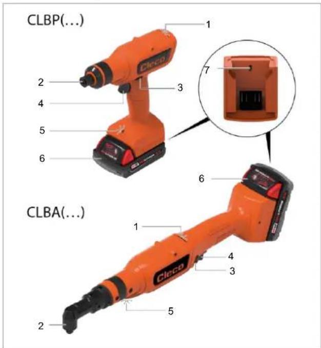
Fig. 1-1: Product description CLBP(...) and CLBA(...)
| 1 | Status light |
| 2 | Output |
| 3 | Reverse Switch |
| 4 | Start Trigger |
| 5 | Work light |
| 6 | Battery (sold separately) |
| 7 | Micro USB-B Port |
5.1 Status Indication
The color and duration of the LED display indicate the status of the rundown and the tool.
| Status light | Work light | Sound | Meaning |
| 15 s | 3 s | — | Result after fastening cycle OK |
| 15 s | 3 s | ♪ | Result after fastening cycle NOK |
| 1 s | 1 s | ♪ | Restart Delay |
| 1 s | 1 s | ♪ | Double Hit Protection |
| — | 3 sAfter releasing the start trigger | — | Work light is activated by start trigger |
 15 s 15 s | G3 s | ♪—♪ | Batch OK (overall tightening result) |
 15 s 15 s | R3 s | ♪—♪ | Batch NOK (overall tightening result) |
 Until the end of the event Until the end of the event | R—RUntil the end of the event | ♪—♪ | Tool overheating |
 Until the end of the event Until the end of the event | — | — | Maintenance alarm |
 Until the end of the event Until the end of the event | RB—Until the end of the event | — | Battery low status |
 Until connected Until connected | — | — | Search WLAN |
 3 s 3 s | — | — | Connected with WLAN |
 Until the end of the event Until the end of the event | RUntil the end of the event | ♪—♪ | General error |
Legend
| Symbol | Explanation |
| [C202] | Green LED lights up |
| B | Blue LED lights up |
 | Red LED lights up |
| Buzzer sound is heard | |
| — | Break |
6 Before Initial Operation
Charging Battery Pack
Battery pack is supplied partly charged and must be charged completely being used for the first time.
▶ See Original Instructions of Milwaukee charger.
▶ Do not use any other battery packs / chargers than the following:
Battery pack 18 V
| Order no. | Capacity |
| T50-1000497 | 2,0 Ah |
| T50-1000498 | 5,0 Ah |
Charger 18 V
| Order no. | Country | |
| T50-1000499 | North America | 1-Bay |
| T50-1000506 | Europe | |
| T50-1000507 | Brazil | |
| T50-1000543 | Argentina | |
| T50-1000544 | United Kingdom | |
| T50-1000545 | China | |
| T50-1000546 | Japan | |
| T50-1000500 | North America | 6-Bay |
| T50-1000508 | Europe | |
| T50-1000547 | United Kingdom |
Setting the torque

Caution
Winding hazard
Unintentional start-up can cause the output to start up and cause serious finger injuries.
▶ Disconnect the tool from the power supply when converting work.
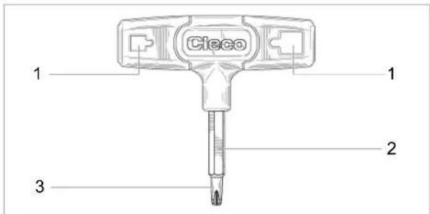
Fig. 1-2: Clutch Adjustment Tool Order no. T50-1001619
| 1 | Square opening for square drive outputs |
| 2 | Hex drive for rotating hex outputs |
| 3 | Screwdriver end for cluch adjustment |
▶ Using the clutch adjustment tool provided:
- turn clockwise for maximum torque.
- turn counterclockwise for minimum torque.
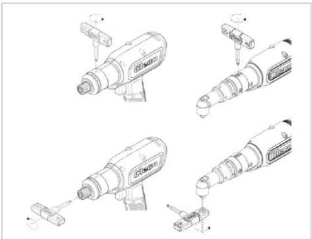
Fig. 1-3: Setting the torque

Recommendation: For best results, start from minimum torque and adjust in the maximum direction until desired torque is achieved.
7 Maintenance
Implement a comprehensive safety maintenance program to provide regular inspection for all phases of tool operation and power supply.

Note
Loss of warranty
Repairs are only permitted by Apex Tool Group authorized personnel. If the tool is opened, the warranty is voided.
▶ If repair is required send the complete tool to Sales & Service Center!
| Maintenance after every ... cycles1 | Measures |
| Daily | ▶ Check all connections.▶ Visual inspection for general damage.▶ Perform a general function test and watch out for excessive vibration or unusual noise. |
| 250,000 | ▶ Send the tool to a certified Sales & Service Center for assessment. |
8 Technical Data
8.1 Right Angle
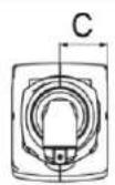
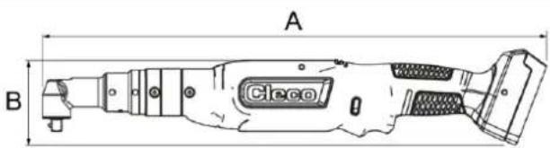
| Tool | Torque Nm (ft-lb) | Speed r/min | Weight | A | B | C | Output | |||
| Order No. | WLAN | Min. | Max. | Min. | Max. | kg (in) | mm (in) | mm (in) | mm (in) | |
| CLBA083 | - | 2.2 | 8 | 92 | 915 | 1.46 | 452.4 | 76.0 | 12.5 |   |
| CLBAW083-(...) | x | (1.6) | (5.9) | (3.2) | (17.81) | (2.99) | (0.49) | |||
| CLBA123 | - | 3.3 | 12 | 65 | 650 | 1.46 | 452.4 | 76.0 | 12.5 |  3/8" 3/8" |
| CLBAW123-(...) | x | (2.4) | (8.8) | (3.2) | (17.81) | (2.99) | (0.49) | |||
| Tool | Torque Nm (ft-lb) | Speed r/min | Weight kg (in) | A mm (in) | B mm (in) | C mm (in) | Output | |||
| Order No. | WLAN | Min. | Max. | Min. | Max. | |||||
| CLBA203 | - | 8.3 | 21 | 36 | 360 | 1.73 | 492 | 76.0 | 15.0 | 3/8" |
| CLBAW203-(...) | x | (6.1) | (15.5) | (3.8) | (19.37) | (2.99) | (0.59) | |||
| CLBA303 | - | 8.3 | 30 | 26 | 255 | 1.73 | 492 | 76.0 | 15.0 | 3/8" |
| CLBAW303-(...) | x | (6.1) | (22.1) | (3.8) | (19.37) | (2.99) | (0.59) | |||
| CLBA403 | - | 15.1 | 41 | 19 | 190 | 1.83 | 513.0 | 76.0 | 18.5 | 3/8" |
| CLBAW403-(...) | x | (11.1) | (11.1) | (4.0) | (20.20) | (2.99) | (0.73) | |||
| CLBA653 | - | 16.0 | 65 | 12 | 115 | 1.93 | 523.6 | 76.0 | 19.0 | 3/8" |
| CLBAW653-(...) | x | (11.8) | (47.9) | (4.3) | (20.61) | (2.99) | (0.75) | |||
Values without battery
WLAN tools, Suffix Order no.:
00: Worldwide
CN: China
EU: Europe
NA: North America
8.2 Pistol
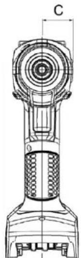
| ToolOrder no. | WLAN | TorqueNm(ft-lb) | Speedr/min | Weightkg(lb) | Amm(in) | Bmm(in) | Cmm(in) | Output | ||
| Min. | Max. | Min. | Max. | |||||||
| CLBP04QCLBPW04Q-(...) | -× | 1.1(0.8) | 4.0(2.9) | 177 | 1770 | 1.05(2.3) | 213.5(8.41) | 209.0(8.23) | 28.5(1.12) | 1/4" |
| CLBP08QCLBPW08Q-(...) | -× | 2.1(1.5) | 8.0(5.9) | 99 | 985 | 1.05(2.3) | 213.5(8.41) | 209.0(8.23) | 28.5(1.12) | 1/4" |
| CLBP12QCLBPW12Q-(...) | -× | 3.2(2.4) | 12.0(8.8) | 70 | 700 | 1.05(2.3) | 213.5(8.41) | 209.0(8.23) | 28.5(1.12) | 1/4" |
Values without battery
WLAN tools, Suffix Order no.:
00: Worldwide
CN: China
EU: Europe
NA: North America
8.3 Emissions
| Order No. | Sound Level Free Speed ISO 15744 [dB(A)] | Sound Level Uncertainty | Vibration Level No Load ISO 28927-2 [m/s2] | Vibration Level Uncertainty |
| CLBP04Q CLBPW04Q-(...) | <70 | ±3 | <2.5 | 1.5 |
| CLBP08Q CLBPW08Q-(...) | <70 | ±3 | <2.5 | 1.5 |
| CLBP12Q CLBPW12Q-(...) | <70 | ±3 | <2.5 | 1.5 |
| CLBA083 CLBAW083-(...) | <70 | ±3 | <2.5 | 1.5 |
| CLBA123 CLBAW123-(...) | <70 | ±3 | <2.5 | 1.5 |
| CLBA203 CLBAW203-(...) | <70 | ±3 | <2.5 | 1.5 |
| CLBA303 CLBAW303-(...) | <70 | ±3 | <2.5 | 1.5 |
| CLBA403 CLBAW403-(...) | <70 | ±3 | <2.5 | 1.5 |
| CLBA653 CLBAW653-(...) | <70 | ±3 | <2.5 | 1.5 |
8.4 Ambient conditions
| Features | Data |
| Operation site | Indoors |
| Working temperature | 0 °C – 40 °C |
| Storage temperature | -25 °C – 65 °C |
| Type of cooling | Convection (self-cooling) |
| Relative humidity | 10 % – 90 %, no condensation |
| Working height | Up to 3000 m (9,843 ft) above sea level |
| Degree of protection EN 60529 | IP40 |
9 Troubleshooting
| Problem | Possible cause | Measure |
| Tool does not start. | No speed programmed. | ► Program speed for all active stages. |
| Tool temperature is too high. | ► Cool down the tool. | |
| Battery voltage is too low. | ► Change battery. | |
| Tool not recognized. | Software is incorrect. | ► Check CellClutch laptop/PC software. |
| Connection to laptop/PC is not available. | ► Check USB cable. ► Check PC driver. | |
| Tool is defective. | ► Change tool. | |
| Tool does not start with counterclockwise rotation activated. | With counterclockwise rotation, parameter for Speed is 0 rpm. | ► Program the speed for counterclockwise rotation: In the CellClutch PC software, set the Speed and Rotation in the Forward and Reverse Application Settings. |
| Tool starts in tightening direction, but not in counterclockwise rota-tion. | No speed programmed for counterclockwise rotation. | ► Program the counterclockwise rotation: In the CellClutch PC software, set the Rotation to Reverse in the Forward and Reverse Application Settings and parameterize the Speed. |
 If Forward is selected for Enabled Direction, the counterclockwise rotation of the reverse switch has no function. If Forward is selected for Enabled Direction, the counterclockwise rotation of the reverse switch has no function. | ||
| Tool shuts off prematurely. | Operator releases start trigger before the controller stops the tool. | ► Make sure that the operator keeps the start trigger pressed throughout the entire sequence. |
| The fastening time exceeds the standard time of 10 seconds. | ► Increase the fastening time. | |
| Tool exceeds the angle set-point. | ► Check the fastening sequence to ensure that the torque shutoff value and/or angle setpoint are correct. Adjust as necessary. ► Check whether the fastening joint has changed significantly. | |
| Tool does not change speed. | Speed is the same in all stages. | ► Make sure that the speed in the stages is cor-rect. |
| Status/work light is disabled. | Disabled by parameter setting. | ► Parameterize the work light: In the Cell-Clutch PC software, select Bright or Dim for Work Light. ► Parameterize the status light: In the Cell-Clutch PC software, select Bright or Dim for Status Light. |
| No-load speed not reached. | Battery voltage is too low. | ► Use a fully charged battery. |
| Expected number of test rundowns is not achieved with one charge of the battery. | Battery is not fully charged. | ► Use a fully charged battery. |
| High torque is needed during a fastening sequence, e.g. for coated fastenings. | If a high torque is needed for a longer period, e.g. for several turns, the number of rundowns that can be achieved with one battery charge will be signifi-cantly reduces. | |
| Battery is at end of life. | After 800 charging cycles, the capacity is reduced to approx. 60%. ► Use new battery. | |
| Status light flashes, see chapter 5.1 Status Indication, page 14. | Encoder is defective. | ► Press start switch. If the status light continues to flash, send the tool to a Sales & Service Center for repair. |
| Tool temperature is too high. | ► Allow the tool to cool down. The current run-down can be terminated, but a new one can-not be started. | |
| Battery voltage is too low. | ► Change battery. | |
| Warning that the next mainte-nance is due. | ► Send the tool to a Sales & Service Center for maintenance. |
EN
10 Disposal
Components and auxiliary materials of the product pose risks to the health and the environment. The tool contains components that can be recycled as well as components that must be specially disposed of.
Separate the components of the packing and segregate the different materials before disposing of them.
▶ Follow the locally applicable regulations.
Observe generally valid disposal guidelines such as, in Germany, the Electrical and Electronic Equipment Act (ElektroG) and the Battery Act (BattG).
▶ Dispose of waste battery packs.
▶ Return the battery to your company collection facility or to Sales & Service Center.
▶ Do not dispose of the batterie packs in the household waste or throw them into fire or water.
2.6 Normen/Standards
Fig. 3-3: ajuste del torque

2.6 Normes / standards
4 Transport / stockage
插图6-3:设置扭矩

Obr. 9-3: Nastavenie krútiaceho momentu

natural_image
Technical line drawing of a mechanical component with no visible text or symbols
| Gereedschap | WLAN | Aanhaalmom. Nm | Toerental t/min | Gewicht | A | B | C | Uitgaan de as | ||
| Bestelnr. | Min. | Max. | Min. | Max. | kg | mm | mm | mm | ||
| CLBP04QCLBPW04Q-(...) | -x | 1,1 | 4 | 177 | 1770 | 1,05 | 213,5 | 209 | 28,5 | 1/4" |
| CLBP08QCLBPW08Q-(...) | -x | 2,1 | 8 | 99 | 985 | 1,05 | 213,5 | 209 | 28,5 | 1/4" |
| CLBP12QCLBPW12Q-(...) | -x | 3,2 | 12 | 70 | 700 | 1,05 | 213,5 | 209 | 28,5 | 1/4" |
Waarden zonder accu
Slika 12-3: nastavitev navora

| No de co-mandă | Capacitate |
| T50-1000497 | 2,0 Ah |
| T50-1000498 | 5,0 Ah |
Încărcător de 18 V
| No de co-mandă | Tară | |
| T50-1000499 | America de Nord | cu 1 compartiment |
| T50-1000506 | Europa | |
| T50-1000507 | Brazilia | |
| T50-1000543 | Argentina | |
| T50-1000544 | Marea Britanie | |
| T50-1000545 | China | |
| T50-1000546 | Japonia | |
| T50-1000500 | America de Nord | cu 6 comparti-mente |
| T50-1000508 | Europa | |
| T50-1000547 | Marea Britanie |
Reglarea cuplului

Precauție
Fig. 13-2: Sculă de reglare, nr. de comandă T50-1001619
Please note that all locations may not service all products.
Contact the nearest Cleco® Sales & Service Center for the appropriate facility to handle your service requirements.

Sales Center
Service Center
NORTH AMERICA | SOUTH AMERICA
DETROIT, MICHIGAN
Apex Tool Group
2630 Superior Court
Auburn Hills, MI 48236
519 Nurigong Street, Albury
NSW 2640
Australia
Phone: +61 2 6058 0300
CHINA
Apex Power Tool Trading
(Shanghai) Co., Ltd.
2nd Floor, Area C
177 Bi Bo Road
Pu Dong New Area, Shanghai
China 201203 P.R.C.
Phone: +86 21 60880320
Fax: +86 21 60880298
INDIA
Apex Power Tool Trading
Private Limited
Gala No. 1, Plot No. 5
S. No. 234, 235 & 245
Indialand Global
Industrial Park
Taluka-Mulsi, Phase I
Hinjawadi, Pune 411057
Maharashtra, India
Phone: +91 020 66761111
JAPAN
Apex Tool Group Japan
Korin-Kaikan 5F,
3-6-23 Shibakoen, Minato-Ku,
Tokyo 105-0011, JAPAN
Phone: +81-3-6450-1840
Fax: +81-3-6450-1841
KOREA
Apex Tool Group Korea
1503, Hibrand Living Bldg.,
215 Yangjae-dong,
Seocho-gu, Seoul 137-924,
Korea
Phone: +82-2-2155-0250
Fax: +82-2-2155-0252
Cleco®
Production Tools
- Disclaimer
- Trademark
- Manufacturer
- Jacobs Chuck
- Importer
- Content
- EN
- DE
- About this document
- Symbols in the text
- Safety
- Warnings and Notices
- Danger
- Warning
- Caution
- Note
- Structure Of Warnings
- Symbols on the Product
- Intended Use
- Foreseeable misuse
- Operator Training
- Standards
- FCC- and IC Compliance
- FCC Responsible party
- General Power Tool Safety Warnings
- Save all warnings and instructions for future reference.
- Work area safety
- Electrical safety
- Personal Safety
- Power tool use and care
- Service
- Specific Safety Instructions for Power Tools
- Personal Protective Equipment
- Power Tool Use and Care
- Items Supplied
- Transport / Storage
- Product Description
- Status Indication
- Before Initial Operation
- Charging Battery Pack
- Setting the torque
- Winding hazard
- Maintenance
- Loss of warranty
- Technical Data
- Right Angle
- Pistol
- Disposal
- Normen/Standards
- Normes / standards
- Transport / stockage
- Reglarea cuplului
- Precauție
- NORTH AMERICA | SOUTH AMERICA
- DETROIT, MICHIGAN
- CHINA
- INDIA
- JAPAN
- KOREA
- 1503, Hibrand Living Bldg.,
Brand : Cleco
Model : CLBA123
Category : Screwdriver