
BC12INKL2401FW - Air Conditioning Be Cool - Free user manual and instructions
Find the device manual for free BC12INKL2401FW Be Cool in PDF.

| Product type | Portable monoblock air conditioner |
| Brand | Be Cool |
| Model | BC12INKL2401FW |
| Cooling power | 12,000 BTU / 10,000 BTU (3.5 kW) |
| Heating power | 2.93 kW |
| Power consumption (cooling) | 975 W |
| Power consumption (heating) | 810 W |
| Input voltage | 220-240 V ~, 50 Hz |
| Max current (cooling) | 4.8 A |
| Refrigerant | R290 (0.23 kg, flammable) |
| Energy efficiency (EER) | 3.6 |
| Energy efficiency (COP) | 3.6 |
| Energy class | A |
| Air circulation | 410 m³/h |
| Noise level (sound power) | 64 dB(A) |
| Dimensions (WxDxH) | 450 x 396 x 745 mm |
| Weight | 31.1 kg |
| Operating modes | Cooling, heating, dehumidification, ventilation, intelligent |
| Special functions | Timer on/off, oscillation, sleep mode, remote control |
| Air filters | 3 washable filters (weekly cleaning recommended) |
| Condensate drainage | Manual or continuous drainage (12.7 mm hose) |
| Protection | IPX0 (no protection against water splashes) |
| Warranty | 2 years (Austria) |
| Connectivity | Wi-Fi 2.4 GHz (for app) |
Frequently Asked Questions - BC12INKL2401FW Be Cool
User questions about BC12INKL2401FW Be Cool
0 question about this device. Answer the ones you know or ask your own.
Ask a new question about this device
Download the instructions for your Air Conditioning in PDF format for free! Find your manual BC12INKL2401FW - Be Cool and take your electronic device back in hand. On this page are published all the documents necessary for the use of your device. BC12INKL2401FW by Be Cool.
USER MANUAL BC12INKL2401FW Be Cool
natural_image
White portable air conditioner unit with black lid and 'BE COOL' branding (no visible text or symbols on body)HERZLICHEN GLÜCKWUNSCH!
Current operating instructions and other languages
Download the latest operating instructions in various languages via the link www.schuss-home.at/downloads or scan the QR code shown. Follow the instructions on the website.

BE COOL

Inhaltsverzeichnis
natural_image
Pure technical line drawing of a coiled pipe or hose assembly without any text, numbers, or symbolsHINWEIS
natural_image
Interior view of a room with a white hose and door, overlooking a window and trees (no visible text or symbols)BE COOL
natural_image
Line drawing of hands inserting a mobile phone into a mobile device (no text or symbols)flowchart
graph LR
    A["Rectangular object with dashed arrow"] --> B["Dashed rectangle with arrow"]
    B --> C["Rectangular shape with dashed arrow"]
    C --> D["Rectangular shape with arrow"]
    D --> E["Rectangular shape with dashed arrow"]
natural_image
Diagram of an air conditioner unit with cooling fan and heat exchanger (no text or labels)BE COOL
natural_image
Line drawing of a portable air conditioner unit with ventilation slots and a cable inserted (no text or symbols)natural_image
Diagram showing a vertical air conditioner unit connected to a curved line with a checkmark (no text or symbols present)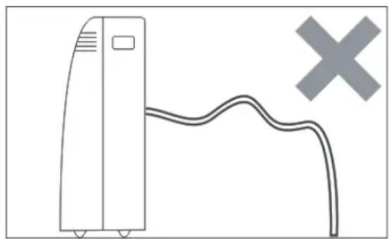
natural_image
Simple line drawing of a server unit connected to a curved cable with a cross symbol (no text or labels)natural_image
White portable air conditioner unit with black lid and 'BE COOL' branding (no visible text or symbols on body)FÉLICITATIONS ! MERCI D'AVOIR CHOISI UN PRODUIT BE COOL.
BE COOL

Table des matières
natural_image
Pure technical line drawing of a coiled cable or pipe connection without any text, numbers, or symbolsREMARQUE
natural_image
Person with white hose opening through a window, viewed from above (no text or symbols visible)BE COOL
PANNEAU DE COMMANDE ET TÉLÉCOMMANDE
natural_image
Line drawing of hands holding a mobile phone with an arrow indicating the device (no text or symbols present)flowchart
graph LR
    A["Rectangular Block"] --> B["Square with Dashed Arrow"]
    B --> C["Square with Dashed Arrow"]
    C --> D["Square with Dashed Arrow"]
    D --> E["Square with Dashed Arrow"]
natural_image
Simple line drawing of a car window with an arrow indicating rotation (no text or symbols)REMARQUE
natural_image
Diagram of an air conditioning unit with cooling fan and heat exchanger (no text or labels)Drainage moyen
natural_image
Line drawing of an air conditioner unit with a cooling fan and attached plug (no text or symbols)natural_image
Diagram showing a vertical air conditioner unit connected to a curved line with a checkmark (no text or symbols present)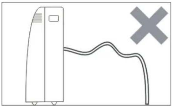
natural_image
Simple line drawing of a server unit connected to a curved cable with a cross symbol (no text or labels)ACTIVITÉS DE DÉBUT/FIN DE SAISON
ACTIVITÉS DE FIN DE SAISON
natural_image
White portable air conditioner unit with black lid and 'BE COOL' branding (no visible text or symbols on body)CONGRATULAZIONI! GRAZIE PER AVER SCELTO UN PRODOTTO BE COOL.
BE COOL

natural_image
Pure technical line drawing of a coiled pipe or hose assembly without any text, numbers, or symbolsNOTA
natural_image
Interior view of a room with a large white hose and window, overlooking a window with trees and greenery (no visible text or symbols)BE COOL
PANNELLO DI CONTROLLO E TELECOMANDO
natural_image
Illustration of hands holding a mobile phone with an arrow indicating the device (no text or symbols present)natural_image
Diagram of an air conditioner unit with cooling fan and ventilation grilles (no text or labels)BE COOL
natural_image
Line drawing of an air conditioning device with a grid-mounted unit and cable inserted (no text or symbols)natural_image
Simple line drawing of a front air conditioner unit with a curved ramp and a checkmark (no text or symbols)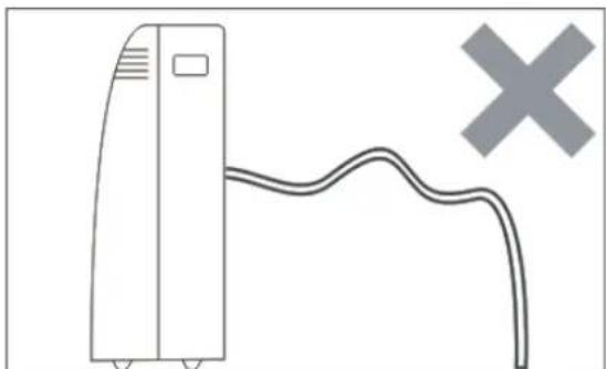
natural_image
Simple line drawing of a server unit connected to a curved cable with a cross symbol (no text or labels)BE COOL
Mobiele airconditioner BC12INKL2401FW

natural_image
White portable air conditioner unit with black lid and 'BE COOL' branding (no visible text or symbols on body)GEFELICITEERD!
BEDANKT VOOR HET KIEZEN VAN EEN PRODUCT VAN BE COOL.
BE COOL
NL Inhoudsopgave
natural_image
Pure technical line drawing of a coiled cable or pipe connection without any text, numbers, or symbolsOPMERKING
natural_image
Interior view of a room with a white duct and air conditioner unit, overlooking a window and trees (no text or symbols visible)BE COOL
BEDIENINGSPANEELE EN AFSTANDSBEDIENING
natural_image
Line drawing of hands holding a mobile phone with an arrow indicating the device (no text or symbols present)HET APPARAAT INSCHAKELEN
flowchart
graph LR
    A["Step 1: Dashed box with arrow"] --> B["Step 2: Solid box with arrow"]
    B --> C["Step 3: Solid box with arrow"]
    C --> D["Step 4: Solid box with arrow"]
    D --> E["Step 5: Solid box with arrow"]
TIPS VOOR CORRECTE TOEPASSING
natural_image
Diagram of an air conditioning unit with cooling fan and heat exchanger (no text or labels)PERMANENTE WATERAFVOER
BE COOL
natural_image
Line drawing of a portable air conditioner unit with ventilation slots and a cable inserted (no text or symbols)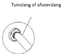
Opmerking:
natural_image
Simple line drawing of a vertical air conditioner unit with a curved ramp and a checkmark (no text or symbols)
natural_image
Simple line drawing of a server unit connected to a curved cable with a cross symbol (no text or labels)BE COOL
natural_image
White portable air conditioner unit with black lid and 'BE COOL' branding (no visible text or symbols on body)natural_image
Pure technical line drawing of a coiled cable or pipe connection without any text, numbers, or symbolsNOTA
natural_image
Interior view of a room with a white hose and a small device on the floor, overlooking a window and trees (no visible text or symbols)BE COOL
PANEL DE CONTROL Y MANDO A DISTANCIA
natural_image
Illustration of hands holding a mobile phone with an arrow indicating the device (no text or symbols present)natural_image
Diagram of an air conditioner unit with cooling fan and heat exchanger (no text or symbols)BE COOL
natural_image
Line drawing of an air conditioner unit with cooling fan and ventilation slots (no text or symbols)natural_image
Simple line drawing of a portable air conditioner unit with a curved ramp and a checkmark (no text or symbols)
natural_image
Simple line drawing of a server unit connected to a curved cable with a cross symbol (no text or labels)BE COOL
ACTIVIDADES AL PRINCIPIO/FINAL DE LA TEMPORADA
ACTIVIDADES AL FINAL DE LA TEMPORADA
natural_image
White portable air conditioner unit with black lid and 'BE COOL' branding (no visible text or symbols on body)GRATULUJEME!
DĚKUJEME, ŽE JSTE SI VYBRALI PRODUKT OD SPOLEČNOSTI BE COOL.
BE COOL
natural_image
Pure technical line drawing of a coiled cable or pipe connection without any text, numbers, or symbolsPOZNÁMKA
natural_image
Interior view of a room with a white hose and window, overlooking a garden (no visible text or symbols)BE COOL
OVLÁDACÍ PANEL A DÁLKOVÉ OVLÁDÁNÍ
BE COOL
DÁLKOVÉ OVLÁDÁNÍ
natural_image
Line drawing of hands holding a mobile phone with an arrow indicating the device (no text or symbols present)flowchart
graph LR
    A["Grid with arrowheads"] --> B["Arrow pointing inward"]
    B --> C["Arrow pointing inward"]
    C --> D["Arrow pointing inward"]
    D --> E["Arrow pointing inward"]
    E --> F["Arrow pointing inward"]
natural_image
Diagram of an air conditioning unit with cooling fan and heat exchanger (no text or labels)BE COOL
natural_image
Line drawing of an air conditioner unit with a cooling panel and attached cable (no text or symbols)natural_image
Diagram showing a vertical air conditioner unit connected to a curved line with a checkmark (no text or symbols present)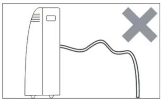
natural_image
Simple line drawing of a server unit connected to a curved cable with a cross symbol (no text or labels)BE COOL
AKTIVITY NA ZAČÁTKU/KONCI SEZÓNY
AKTIVITY NA KONCI SEZÓNY
natural_image
White portable air conditioner unit with black lid and 'BE COOL' branding (no visible text or symbols on body)GRATULUJEME!
ĐAKUJEME, ŽE STE SI VYBRALI PRODUKT OD SPOLOČNOSTI BE COOL.
BE COOL

natural_image
Pure technical line drawing of a coiled cable or wire connection without any text, numbers, or symbolsPOZNÁMKA
natural_image
Interior corner of a room with a large white hose and window, overlooking a window view with trees and a fence in the background (no visible text or symbols)BE COOL
OVLÁDACÍ PANEL A DIAL'KOVÉ OVLÁDANIE
natural_image
Line drawing of hands holding a mobile phone with an arrow indicating the device (no text or symbols present)natural_image
Diagram of an air conditioner unit with cooling fan and heat exchanger, showing internal components and airflow direction (no text or labels)BE COOL
Stredné odvodnenie
natural_image
Line drawing of an air conditioner unit with cooling fan and ventilation slots (no text or symbols)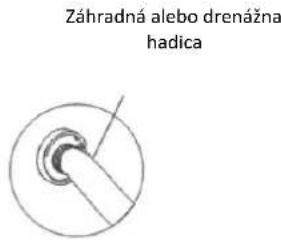
natural_image
Simple line drawing of a vertical air conditioner unit with a curved ramp and a checkmark (no text or symbols)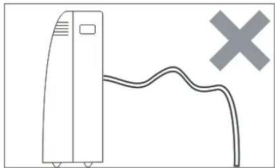
natural_image
Simple line drawing of a server unit connected to a curved cable with a cross symbol (no text or labels)AKTIVITY NA ZAČIATKU/KONCI SEZÓNY
AKTIVITY NA KONCI SEZÓNY
natural_image
White portable air conditioner unit with black lid and 'BE COOL' branding (no visible text or symbols on body)FELICITĂRI! VĂ MULTUMIM CĂ AȚI ALES UN PRODUS BE COOL.
BE COOL

Cuprins
natural_image
Interior view of a room with a white hose and a small appliance on a counter, overlooking a window with trees and greenery in the background (no visible text or symbols)BE COOL
PANOU DE CONTROL ŞI TELECOMANDĂ
BE COOL
CONTROL DE LA DISTANTĂ
natural_image
Line drawing of hands holding a mobile phone with an arrow indicating the device (no text or symbols present)flowchart
graph LR
    A["Rectangular Shape"] --> B["Hexagonal Block"]
    B --> C["Grid Structure"]
    C --> D["Arrow Up/Down"]
    D --> E["Arrow Down/Up"]
    E --> F["Arrow Left/Right"]
natural_image
Diagram of an air conditioning unit with cooling fan and heat exchanger (no text or labels)BE COOL
natural_image
Line drawing of an air conditioner unit with cooling fan and ventilation slots (no text or symbols)natural_image
Simple line drawing of a vertical air conditioner unit with a curved ramp and a checkmark (no text or symbols)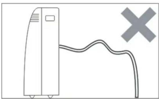
natural_image
Simple line drawing of a server unit connected to a curved cable with a cross symbol (no text or labels)BE COOL
ACTIVITĂȚI LA ÎNCEPUTUL/FINALUL SEZONULUI
ACTIVITĂȚI LA SFÂRȘITUL SEZONULUI
natural_image
White portable air conditioner unit with black lid and 'BE COOL' branding (no visible text or symbols on body)GRATULACJE! DZIEKUJEMY ZA WYBRANIE PRODUKTU OD BE COOL.
BE COOL

Spis treści
natural_image
Pure technical line drawing of a coiled cable or wire connection without any text, numbers, or symbolsUWAGA
natural_image
Interior view of a room with a large white hose and a small appliance on a bed, overlooking a window with trees and greenery in the background (no visible text or symbols)BE COOL
natural_image
Line drawing of hands holding a mobile phone with an arrow indicating the device (no text or symbols present)flowchart
graph LR
    A["Rectangular Grid"] --> B["Square Grid"]
    B --> C["Arrow to Next Step"]
    C --> D["Square Grid"]
    D --> E["Arrow to Next Step"]
natural_image
Diagram of an air conditioner unit with cooling fan and heat exchanger (no text or labels)BE COOL
natural_image
Line drawing of a portable air conditioner unit with ventilation slots and a connector (no text or symbols)natural_image
Simple line drawing of a vertical air conditioner unit with a curved ramp and a checkmark (no text or symbols)
natural_image
Simple line drawing of a server unit connected to a curved cable with a cross symbol (no text or labels)BE COOL
DZIAŁANIA NA POCZĄTKU/KOŃCU SEZONU
DZIAŁANIA NA KONIEC SEZONU
natural_image
White portable air conditioner unit with black lid and 'BE COOL' branding (no visible text or symbols on body)ČESTITAMO!
HVALA, KER STE IZBRALI IZDELEK BE COOL.
BE COOL
natural_image
Interior view of a room with a white hose and a window, showing outdoor plants and trees in the background (no text or symbols visible)BE COOL
NADZORNA PLOŠČA IN DALJINSKI UPRAVLJALNIK
natural_image
Line drawing of hands holding a mobile phone with an arrow indicating the device (no text or symbols present)Varnostna navodila za zamenjavo baterije:
flowchart
graph LR
    A["Rectangular Shape with Dashed Arrow"] --> B["Grid with Arrow"]
    B --> C["Grid with Arrow"]
    C --> D["Grid with Arrow"]
natural_image
Simple line drawing of a car window with an arrow indicating rotation (no text or symbols)OPOMBA
natural_image
Diagram of an air conditioning unit with cooling fan and heat exchanger (no text or labels)BE COOL
Srednja drenaža
natural_image
Line drawing of a portable air conditioner unit with cooling fan and ventilation slots (no text or symbols)natural_image
Simple line drawing of a vertical air conditioner unit with a curved ramp and a checkmark (no text or symbols)
natural_image
Simple line drawing of a server unit connected to a curved cable with a cross symbol (no text or labels)DEJAVNOSTI NA ZAČETKU/KONCU SEZONE
DEJAVNOSTI OB KONCU SEZONE
natural_image
White portable air conditioner unit with black lid and 'BE COOL' branding (no visible text or symbols on body)ČESTITAMO! HVALA VAM ŠTO STE ODABRALI PROIZVOD BE COOL.
BE COOL

natural_image
Interior view of a room with a large white hose hanging from a window, overlooking a window and trees (no visible text or symbols)BE COOL
UPRAVLJAČKA PLOČA I DALJINSKI UPRAVLJAČ
natural_image
Line drawing of hands holding a mobile phone with an arrow indicating the device (no text or symbols present)Sigurnosne upute za zamjenu baterije:
- Kada se daljinski upravljač zamijeni ili odloži, baterije se moraju ukloniti i odložiti u skladu s važećim zakonima jer su štetne za okoliš.
- Stare i nove baterije ne smiju se miješati. Ne miješajte alkalne, standardne (ugljik-cink) ili punjive (nikl-kadmij) baterije.
- Ne bacajte baterije u vatru. Baterije mogu eksplodirati ili iscuriti.
- Ako se daljinski upravljač neće koristiti dulje vrijeme, izvadite baterije.
OBAVIJEST
Ako daljinski upravljač treba zamijeniti ili zbrinuti, baterije se moraju izvaditi i pravilno zbrinuti u skladu s važećim propísima!
flowchart
graph LR
    A["Rectangular Shape"] --> B["Grid Shape"]
    B --> C["Arrow Direction"]
    C --> D["Arrow Direction"]
    D --> E["Grid Shape"]
    E --> F["Arrow Direction"]
natural_image
Diagram of an air conditioning unit with cooling fan and heat exchanger (no text or labels)- Za uklanjanje prašine nakupljene u zračnim filtrima koristite usisivač.
- Ako je filtar za zrak jako zaprljan, možete ga uroniti u toplu vodu i nekoliko puta isprati – međutim, temperatura vode ne smije prelaziti 40°C.
- Nakon pranja, ostavite filtar zraka da se temeljito osuši i zatim ga ponovno umetnite.
BE COOL
OBAVIJEST
BE COOL
Srednja drenaža
natural_image
Line drawing of a portable air conditioner unit with ventilation slots and a connector (no text or symbols)Vrtno crijevo ili odvodno crijevo
Obavijest:
natural_image
Diagram showing a vertical air conditioner unit connected to a curved line with a checkmark (no text or symbols present)
natural_image
Simple line drawing of a server unit connected to a curved cable with a cross symbol (no text or labels)BE COOL
AKTIVNOSTI NA POČETKU/KRAJU SEZONE
AKTIVNOSTI ZA KRAJ SEZONE
Mobile air conditioner BC12INKL2401FW
natural_image
White portable air conditioner unit with black lid and 'BE COOL' branding (no visible text or symbols on body)CONGRATULATIONS! THANK YOU FOR CHOOSING A PRODUCT FROM BE COOL.
BE COOL

Table of contents
| Important information on safety, location and electrical connection |
| Recycling, disposal, declaration of conformity |
| Description of the device and scope of delivery |
| Commissioning |
| Description of the display |
| Control panel and remote control |
| Set functions |
| Tips for correct use |
| Maintenance and cleaning |
| Activities at the beginning/end of the season |
| Self-diagnosis |
| Troubleshooting |
| Technical information |
| Guarantee |
PLEASE READ THE OPERATING INSTRUCTIONS CAREFULLY BEFORE STARTING ASSEMBLY, INSTALLATION, OPERATION OR MAINTENANCE. PROTECT YOURSELF AND OTHERS BY FOLLOWING THE SAFETY INSTRUCTIONS. FAILURE TO FOLLOW THE INSTRUCTIONS COULD RESULT IN PERSONAL INJURY AND/OR PROPERTY DAMAGE AND/OR INVALIDATE THE WARRANTY!
IMPORTANT INFORMATION ON SAFETY, LOCATION AND ELECTRICAL CONNECTION.
- Please read all instructions carefully before using the appliance.
- Only use this appliance in accordance with the guidelines in the operating instructions. Any other use not recommended by the manufacturer could result in fire, electric shock or personal injury.
- This appliance is intended exclusively for the air conditioning of living spaces in households and must not be used for any other purpose.
- The appliance is not suitable for continuous and precision operation and should not be used for cooling electrical systems (e.g. in server rooms).
- It is forbidden to adapt or modify the characteristics of this appliance in any way and only use spare parts and accessories recommended by the manufacturer (failure to do so will invalidate the guarantee and warranty).
- For any repairs to the appliance, mains plug or cable, always and only contact customer service centres authorised by the manufacturer. You can find the customer service centres online at www.becool.at.
• - Remove the packaging and ensure that the air conditioner is not damaged. If in doubt, do not use the air conditioner and contact the service centre or your dealer.
- Keep children away from packaging material. Choking hazard if swallowed!
BE COOL
- If the power supply cable is damaged, it must be replaced by the manufacturer or an authorised service centre in order to avoid all possible risks.
- The appliance must be installed in accordance with local installation and operating regulations for electrical systems.
- The electrical socket into which you connect the appliance must not be defective or loose and must be suitable for the required current load and, above all, reliably earthed. If in doubt, have your electrical installation checked by a qualified electrician.
- Before connecting to the mains, you must check that the type of current and mains voltage correspond to the information on the appliance rating plate on the back.
- Avoid using an extension cable, as this could overheat and cause a fire.
- Do not twist or kink the mains cable.
- This appliance may only be used by adults.
- Children under 8 years of age and persons with reduced physical, mental, sensory or intellectual capabilities or lack of experience and knowledge may only use this appliance if they have been given supervision and instruction concerning use of the appliance in a safe way and if the hazards involved have been clearly explained.
- Do not allow children to play with the packaging and make sure that children do not play with the appliance.
- Do not use the air conditioner outdoors.
- Do not use the appliance with wet hands.
- Never operate the appliance in rooms where gas, oil or sulphur are present.
- Do not install the appliance near heat sources (e.g. next to heating systems and gas boilers) and avoid direct sunlight.
- Maintain a minimum distance of at least 50 cm from flammable substances (e.g. alcohol, etc.) or pressurised containers (e.g. spray containers).
- Do not use the air conditioner near water or high humidity, e.g. in a damp cellar, next to a swimming pool, bathtub or shower. Ensure that no water enters the appliance.
- Do not place any heavy or hot objects on the appliance and never cover the appliance.
- Never insert fingers, pens or other objects into the appliance and ensure that the air inlet and outlet are never blocked.
- Always switch off the appliance before disconnecting the mains plug.
- Do not pull on the mains cable to disconnect the appliance from the mains. Always pull on the plug to disconnect the mains cable. Do not touch the plug with wet hands to avoid electric shocks.
- Unplug the appliance when not in use, before cleaning, maintenance or moving from one place to another.
- If the appliance is faulty, switch it off using the on/off button on the control panel and contact the customer hotline.
- Keep the air conditioner in good condition by maintaining and cleaning the appliance.
- The air filter must be cleaned at least once a week.
- Store the appliance upright in a safe, dry place that is inaccessible to children when it is not in use. Do not cover the appliance with plastic packaging.
- Store the appliance in a room without any operating sources of ignition (e.g. open fire, an operating gas appliance or an electric heater with an open heat source).
- The air conditioner must be transported in an upright position or slightly on its side. Empty the internal condensation container beforehand. Wait at least one hour after transporting the appliance before switching it on.
- For any repairs to the appliance, mains plug or cable, always and only contact customer service centres authorised by the manufacturer.
- Do not use any means to accelerate or eliminate the defrosting process, the appliance will do this automatically.
- If you have any questions about maintenance, you can contact the customer hotline/service centre authorised by the manufacturer.
BE COOL
WARNING
The main switch and the On/Off switch should not be used as the sole means of disconnecting the power supply. Always disconnect the mains plug before starting maintenance work or moving the appliance.
To avoid the risk of electric shock, disconnect the plug from the socket when the appliance is not in use and before cleaning.
SPECIFIC INFORMATION ON THE REFRIGERANT R290
- R290 is a refrigerant in accordance with EC environmental regulations.
- The refrigerant is odourless.
- The appliance must be installed in a room where there are no sources of ignition during operation (e.g. open fire, operating gas and electrical appliances with an open heat source)
- Do not perforate or burn the air conditioner.
- Ensure that the cooling circuit is not drilled into.
- Non-ventilated rooms in which the appliance is installed, operated or stored must be constructed in such a way that any refrigerant losses do not accumulate. This prevents the risk of fire or explosion caused by ignition of the refrigerant by electric ovens, cookers or other ignition sources.
-
The device must be stored in such a way that no mechanical damage can occur.
-
Persons working on or intervening in a refrigeration circuit must be in possession of a valid certificate issued by an authorised authority, which certifies their expertise in handling refrigerants by means of an assessment specification recognised by industry associations.
-
Repairs must be carried out in accordance with the instructions of the appliance manufacturer. Repair and maintenance work that requires the intervention of other specialised personnel must be carried out under the supervision of the specialist responsible for handling flammable refrigerants.
BE COOL
Recycling, disposal, declaration of conformity
 | RECYCLINGThe packaging materials can be recycled. It is therefore recommended to dispose of them in sorted waste |
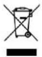 | DISPOSALThe "crossed-out dustbin" symbol requires the separate disposal of waste electrical and electronic equipment (WEEE). Electrical and electronic equipment may contain hazardous and environmentally harmful substances. Therefore, do not dispose of them in unsorted residual waste, but at a designated collection point for waste electrical and electronic equipment. This will help to protect resources and the environment. For further information, please contact your dealer or the local authorities. Directive 2012/19/EU |
 | BATTERY DISPOSALIn accordance with current legislation regarding batteries, accumulators, and related waste, the symbol of the crossed-out bin on the battery indicates that it is prohibited to dispose of used batteries in household waste. Batteries and accumulators contain highly polluting substances. The user is obliged to dispose of used batteries at designated collection points in the municipality or in the appropriate containers. This service is free of charge. In this way, legal requirements are met and the environment is protected.These symbols can be found on batteries:Li = Battery contains lithiumAl = Battery contains alkaliMn = Battery contains manganeseCR 2025 (Li); AA (Al, Mn); AAA (Al, Mn) |
| CE | DECLARATION OF CONFORMITYWe hereby confirm that this product complies with the essential requirements, regulations and directives of the EU. You can view the detailed declaration of conformity at any time under the following link:https://www.schuss-home.at/downloads |
Errors and technical changes excepted.
BE COOL
DESCRIPTION OF THE DEVICE AND SCOPE OF DELIVERY
| 1. Control element2. Carrying handle (on both sides)3. Castors4. Air outlet5. Remote control receiver | 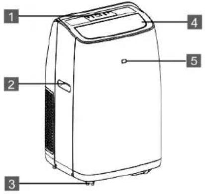 |
| 6. Air inlet grille7. Exhaust air outlet8. Air inlet grille9. Mains plug10. Cable holder11. Air inlet grille12. Condensation outlet | 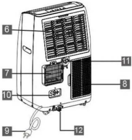 |
| Exhaust air hose with adapterPlease join the parts together by twisting the two adapters onto the air hose. | 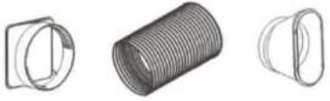 |
| Window bracket (B) + extension rail (A)Window bracket for roller shutters and sliding windows. |  |
| Remote control | 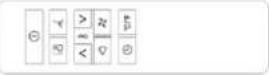 |
| Condensation hose | 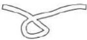 |
BE COOL
COMMISSIONING
PREPARATION FOR USE
IMPORTANT!
Leave the appliance upright for at least 2 hours before using it for the first time and make sure that the condensation outlet is properly sealed.
- Place the appliance on a level surface near the window with a properly earthed socket.
- The distance to walls or other objects must be at least 50 cm.
- Before using the appliance, make sure that both the air inlet and outlet are free of obstacles and not blocked.
- Observe the instructions in the chapter "Important information on safety, location and electrical connection".
INSTALLATION
You can put your air conditioning unit into operation in just a few steps:
| 1. assemble the exhaust air hose Extend the hose on both sides by pulling it apart. Then screw the adapters on | 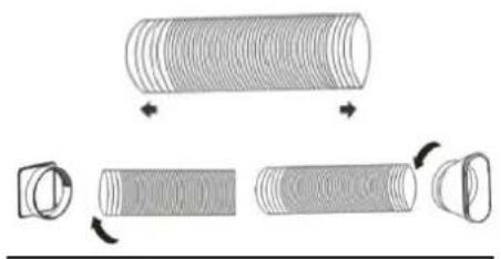 |
| 2. install the exhaust air hose on the appliance Push the exhaust air hose into the opening provided on the back of the appliance. (from top to bottom) | 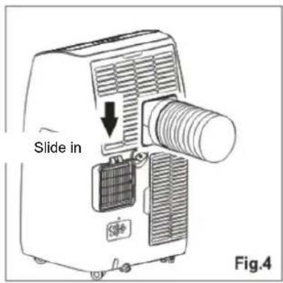 |
BE COOL
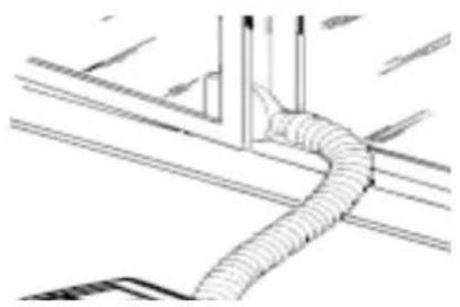
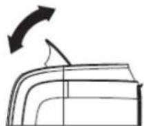
3. installation on a window/balcony without window bracket
Now place the air conditioner near a window or balcony door.
Adjust the length of the hose so that it reaches the window/balcony door.
Check that the air in the hose can flow freely.
Open the window slightly and attach the exhaust air hose taper there.
natural_image
Pure technical line drawing of a coiled cable or pipe connection without any text, numbers, or symbols4. installation on roller shutter and sliding windows using the window bracket
Place the window bracket on/in the window frame, slide it out over the entire window width/height by pulling the extension rail (A) out of the window bracket (B). Then screw the screws (D) into the corresponding holes that correspond to the width of your window to ensure that there are no gaps in the mounted window bracket after fastening.
Lower or slide the window onto the bracket and slide the exhaust air hose taper into the cut-out.
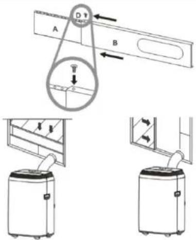
NOTE
If the window opening is smaller than the minimum length of the window slider set, cut the end without the hatch until it fits into the window.
Never cut into the hole in the window slider set.
BE COOL
| ATTENTION!!!Please observe the following instructions for both installations: | The exhaust air hose must be as short as possible and have as few bends as possible so that the air can flow freely. |
| The air conditioner should be placed on a firm floor to minimise noise and vibrations. Place the appliance on a straight, level surface that is strong enough to support the appliance. | |
| The appliance must be installed within reach of a properly earthed socket outlet. Never obstruct the air inlet or outlet openings of the appliance. | |
| The exhaust air hose is designed specifically for this appliance. Do not extend it or replace it with another hose, otherwise you could damage the appliance. |
RECOMMENDATION FROM BE COOL
We recommend a BE COOL Hot-Air Stop for installation on windows, balcony doors or sliding doors.
These offer the following advantages:
- No warm air flows into the living space→ therefore energy savings
- Quick and easy installation
• Durable, water-repellent material - Opening and closing possible
- Washable
Available from your air conditioning supplier.
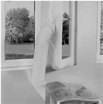
natural_image
Interior view of a room with a white hose and a wall-mounted device, overlooking a window with trees and greenery (no visible text or symbols)BE COOL
CONTROL PANEL AND REMOTE CONTROL
Description of the control panel and remote control
The buttons on the control panel and the remote control have the same functions:
OPERATING FIELD
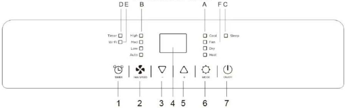
- timer button
- speed button
- "-" button
- display
- "+" button
- mode button
- on/off button
A Mode Indicator
B Speed indicator
C Sleep mode indicator
D Timer indicator
E WIFI
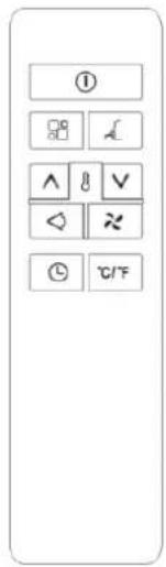
REMOTE CONTROL

Speed button

Oscillation

Sleep mode

Increase button

Lowering button

On/off button

Mode button

Timer button

Unit change button
BE COOL
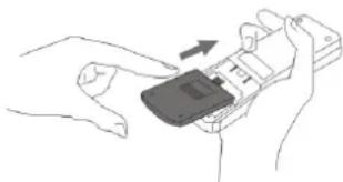
REMOTE CONTROL
Preparing the remote control - Inserting or replacing batteries
First commissioning of the remote control or replacement of the betterien:
- Remove the cover on the back of the remote control.
- Insert two "AAA" 1.5V batteries in the correct position (see instructions in the battery compartment)
natural_image
Line drawing of hands holding a mobile phone with an arrow indicating the device (no text or symbols present)Safety instructions for battery replacement:
- If the remote control is replaced or disposed of, the batteries must be removed and disposed of in accordance with the applicable legislation, as they are harmful to the environment.
- Old and new batteries must not be mixed. Do not mix alkaline, standard (carbon zinc) or rechargeable (nickel cadmium) batteries.
- Do not dispose of batteries in a fire. Batteries can explode or leak.
- If the remote control will not be used for a long period of time, remove the batteries.
NOTE
If the remote control needs to be replaced or disposed of, the batteries must be removed and disposed of properly in accordance with the applicable regulations!
Also remove the batteries if the remote control will not be used for a longer period of time to prevent corrosion damage.
If the batteries need to be replaced, always replace both with the same type and charge status.
SET FUNCTIONS
You can set all functions directly on the appliance or using the remote control.
The indicator lights on the control panel display light up depending on the set function.
Point the remote control directly at the front of the appliance and make sure that there are no obstacles between the remote control and the appliance.
SWITCH ON THE DEVICE
- Connect the appliance to the earthed socket.
- Press the ⏻ button to switch on the device.
NOTE
Never switch off the air conditioner by unplugging it directly from the mains. To switch off, always press the On/Off button and wait a few minutes before disconnecting the appliance from the mains. This allows the appliance to run through a cycle of checks to verify its functionality.
BE COOL
SET MODES
Cooling mode
Ideal for warm and humid weather to cool down the room.
- Press the button or on the remote control until the COOL LED on the display lights up.
- Now use and to select the desired target temperature (18°C - 32°C/64°F - 90°F).
- Use the button to select one of the three fan speeds.
NOTE
In summer, it is recommended to set a room temperature between 24^ and 27^ . In any case, it is not advisable to select a temperature that is far below the outside temperature.
Ventilation/fan mode
Only the fan runs in this mode.
- Press the button or on the remote control until the "Ventilation LED" on the control element lights up.
- Now use the button to select from the four speed levels.
- The screen displays "==" as high speed, "==" as medium speed & "--" as low speed.
Dehumidification/drying mode
Ideal for reducing humidity in rooms (e.g. in spring and autumn, for damp rooms, during periods of rain, etc.).
- Press the ⚙ button or 📁 on the remote control several times until the drying mode LED on the control element lights up. The dehumidifier symbol "dh" appears on the display.
- The appliance automatically adjusts the temperature depending on the Current ambient temperature.
- The fan speed is also automatically set to the lowest level.
Heating mode
To set this mode correctly:
- Press the "💡" or "☐" button on the remote control repeatedly until the heating symbol lights up.
- Select the target temperature 13°C-27°C (55°F-81°F) by pressing the "∧" or "∨" button until the corresponding value is displayed.
- Select the desired fan level by pressing the " ✖" button to select the desired fan level: High / Medium / Low / Auto.
- The water is extracted from the air and collected in the tank.
BE COOL
- When the tank is full, the appliance switches off and "Ft" (full tank) appears on the display. The tank lid must be pulled out and the water emptied. Drain the remaining water into a bowl. When all the water has been drained, replace the lid.
• After emptying the tank, the appliance restarts.
Note:
- If the appliance is used in very cold rooms, a defrosting process takes place automatically, which briefly interrupts normal operation. During this process, it is normal for the noise level of the appliance to change.
- In this mode, it may be necessary to wait a few minutes before the appliance emits hot air.
- During this mode, the fan may be active for a short time, even if the set temperature has already been reached.
Smart mode
In smart mode, the appliance decides for itself whether to run in cooling, ventilation or heating mode - this mode reduces power consumption.
- Press the ⚙ button or "☐" on the remote control several times until the following appears on the display:
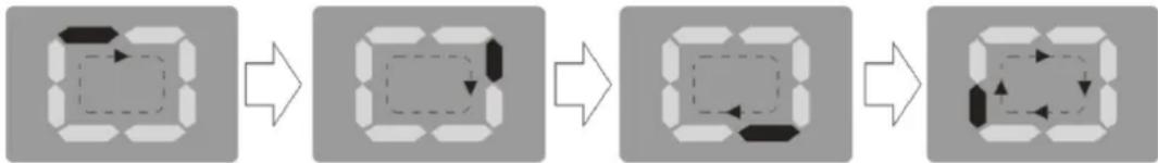
flowchart
graph LR
    A["Rectangular object with dashed arrow"] --> B["Dashed rectangle with arrow"]
    B --> C["Rectangular shape with dashed arrow"]
    C --> D["Rectangular shape with arrow"]
    D --> E["Rectangular shape with dashed arrow"]
- Select the desired fan speed using the button.
- The appliance operates in heating mode when the room temperature is below 20^ C. It operates in fan mode when the room temperature is between 20^ C and 23^ C and in cooling mode when the room temperature is above 23^ C.
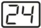
Timer
This function allows you to switch the appliance on and off on a timed basis.
Programmed switch-on
- Switch on the appliance and select the desired modes (e.g.: cooling mode, 24°C, high speed).
- Now switch off the device and then press the button.
- The TIMER LED on the control element flashes and the number of hours is shown on the display.
Davonated
- Press the button repeatedly until the desired number of hours appears on the display. Now wait approx. 5 seconds until the timer sets itself automatically and the TIMER_LED lights up continuously.
- After the programmed time has elapsed, the appliance switches on automatically and operates according to the settings you have selected.
- To switch off the timer, press the ⏻ button again.
BE COOL
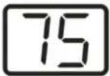
Programmed switch-off
- Press the button while the device is switched on.
- The TIMER LED on the control element flashes and the number of hours is shown on the display.
- Press the button until the desired number of hours appears on the display. Now wait approx. 5 seconds until the timer sets itself automatically and the TIMER symbol lights up permanently.
• After the programmed time has elapsed, the appliance switches off automatically.
Changing the temperature unit
You have the option of selecting between DEGREE and FAHRENHEIT:
| DEVICE | REMOTE CONTROL |
| Press and hold the and buttons simultaneously for approx. 3 seconds to change the temperature unit: | Press the button to change the temperature unit: |
 |  |
The following functions can only be set using the remote control:
Oscillation
- Use the button to activate the oscillation of the appliance.
- Press the button again to deactivate the function.
NOTE
This function distributes the discharged air vertically. This allows you to achieve horizontal air distribution in the room.
SLEEP
This function is particularly useful for operating the appliance at night, as it gradually reduces its output.
Press the button to start or stop the function.
The device now works automatically as follows:
- It reduces the screen brightness.
- It reduces the volume.
- It reduces the fan speed and also maintains the low speed.
- In COOL mode, the set temperature is increased by 1°C per hour within 2 hours. This newly set temperature is maintained for the following 6 hours before the appliance switches off automatically.
- In HEATING mode, on the other hand, the selected temperature is reduced by 1°C per hour over a period of 3 hours. This newly set temperature also remains constant for the following 5 hours before the appliance switches off automatically.
- The SLEEP function is still available in DRY and SMART mode.
BE COOL
TIPS FOR CORRECT APPLICATION
Here are some tips on how to optimise the performance of the air conditioner:
| Close the windows and doors in the room to be air-conditioned. | 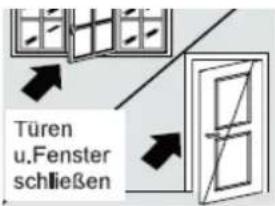 |
| Protect the room from direct sunlight with curtains, blinds or shutters. This will save you energy. | 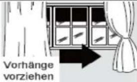 |
| Do not place any objects on the appliance and do not cover the air inlet and air outlet. Keep the grilles clear. | |
| Make sure that no heat sources are operating in the room. | |
| Never use the appliance in very damp rooms (e.g. laundry rooms). | |
| Do not use the appliance outdoors. | |
| Make sure that the air conditioner is standing on a level floor. | |
MAINTENANCE AND CLEANING
CLEAN THE AIR FLITER
To ensure that the air conditioner functions efficiently, you should clean the air filter after every week of operation.
- Switch off the appliance before cleaning, wait a few minutes and then pull out the plug to disconnect the appliance from the power supply.
- Disconnect the exhaust air hose.
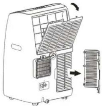
- The air conditioner has a total of 3 air filters:
Open the two air inlet grilles at the back and remove the filter underneath, as shown in the picture:
natural_image
Diagram of an air conditioner unit with cooling panel and fan, showing internal structure and airflow direction (no text or labels)- Use a hoover to remove the dust accumulated in the air filters.
- If the air filter is very dirty, you can immerse it in hot water and rinse it several times - the water temperature should not exceed 40^ C, however.
- Allow the air filter to dry out well after washing and then replace it.
BE COOL
NOTE
Never use the appliance without a filter.
CLEANING THE HOUSING
Switch off the appliance before cleaning, wait a few minutes and then always pull out the plug to disconnect the appliance from the power supply.
Clean the appliance with a moderately damp cloth and then wipe it with a dry cloth.
- For safety reasons, never clean the appliance with water. This could be dangerous.
- Never use petrol, alcohol or solvents for cleaning.
- Do not spray insecticides or similar agents on the air conditioner.
EMPTY WATER TANK MANUALLY
The appliance has an automatic water evaporation system. The compressor is cooled by circulating the condensed water, which not only improves the cooling capacity but also saves energy.
If the water tank is still full, "Ft" appears on the control panel display and the air conditioner switches off automatically. The appliance is locked until the water tank is empty.
To empty the condensation water tank, follow the steps below:
- Pull the mains plug out of the socket.
- Place a drip tray under the condensation water outlet at the back of the appliance, carefully remove the cap from the outlet and allow the water to drain into the drip tray.
- At the end, you can tilt the air conditioner slightly - but not more than 30°.
- As soon as the tank is completely empty, carefully reinsert the plug into the water outlet.
- Plug in the mains plug and restart the appliance.
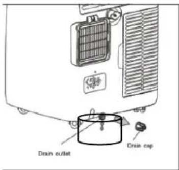
PERMANENT WATER DRAINAGE
You have the option of installing a permanent water drain so that you do not have to empty the water tank manually every time you intend to use the appliance for a longer period of time (or if the water pump breaks down).
To install the permanent water drain, please proceed as follows:
- Before you attach a suitable water drain hose (12.7 mm) to the respective outlet, the water tank must be completely empty.
- Remove the plug from the permanent condensation water outlet and attach the water drain hose.
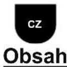
- Insert the other end of the hose into a collection vessel or drain, ensuring that the hose is not laid higher than the drain valve and is not kinked.
BE COOL
- If the permanent drain is removed, be sure to carefully reinsert the plug.
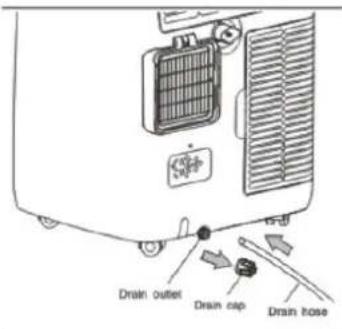
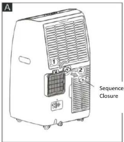
Medium drainage
If the appliance is running in dry mode, you can select the following method for draining.
- Disconnect the device from the power source.
- Remove the drain plug (fig. A). Some residual water may leak out during this process, so please have a drip tray ready.
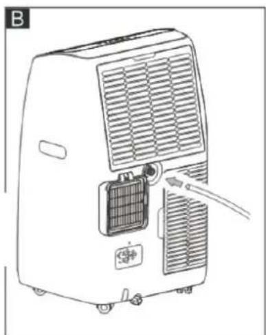
- Connect the drain hose (1/2" or 12.7mm, may not be supplied). (Fig. B)
- The water can be continuously drained through the hose into a floor drain or bucket.
- Switch on the device.
natural_image
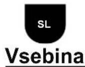
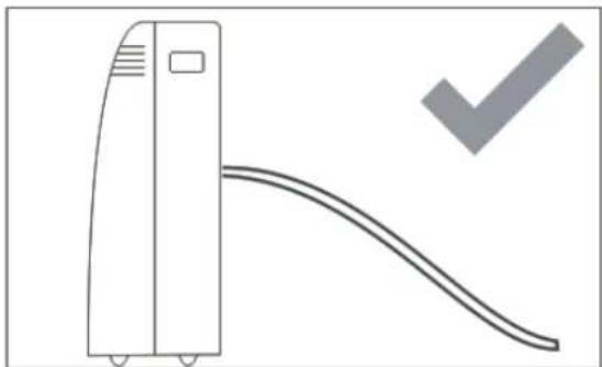
Line drawing of a portable air conditioner unit with cooling fan and ventilation slots (no text or symbols)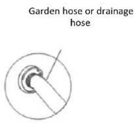
Note:
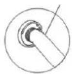
Make sure that the height and cross-section of the drain hose are not higher than the drain outlet, otherwise the water tank cannot be emptied:
natural_image
Simple line drawing of a vertical air conditioner unit with a curved ramp and a checkmark (no text or symbols)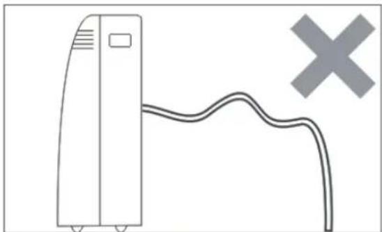
natural_image
Simple line drawing of a server unit connected to a curved cable with a cross symbol (no text or labels)ACTIVITIES AT THE BEGINNING/END OF THE SEASON
ACTIVITIES AT THE END OF THE SEASON
- Carefully empty the condensation water tank completely into a suitable container as described in the section "Emptying the water tank".
BE COOL
- Run the air conditioner in fan/blower mode for 2 hours until the inside of the appliance is completely dry.
- Switch off the appliance and disconnect the mains plug.
- Clean the filter and insert it again after it has dried (see section "Cleaning the air filter").
- Remove the exhaust air hose and accessories and store them carefully.
- Remove the batteries from the remote control
- Pack the device and store it in a cool, dry place.
CHECKS AT THE START OF THE SEASON
- Check that the power supply cable and socket are in order and that the earthing is functional.
- Ensure that the plug is carefully fitted in the condensation water outlet and that the filters are in place.
- Follow the installation and safety instructions carefully.
SELF-DIAGNOSIS
The air conditioner has a self-diagnosis system to identify some malfunctions. The error messages are displayed on the screen:
| DISPLAY | HANDLING |
LOW TEMPERATURE | The appliance is equipped with a frost protection mechanismequipped to prevent excessive formation of ice to prevent.The device switches off and starts automatically again as soon as the defrosting process is complete |
| LOW TEMPERATURE (frost prevention) | |
FULL TANK | Empty the water tank as described in the chapter "Emptying the water tank". |
| FULL TANK(water tank is full) | |
PROBE FAILURE | As soon as this error message appears on the displayis displayed, please contact the service line or inform yourself on the homepagewww.becool.atvia the service centres. |
| PROBING ERROR(sensor damaged) |
BE COOL
TROUBLESHOOTING
Before contacting our customer hotline/service centre, please check whether the fault can be rectified using the instructions below.
| PROBLEM | POSSIBLE CAUSE | SOLUTION |
| The air conditioner does not switch on. | Power failure | Wait for the power supply to be restored. |
| The device is not connected to the power supply. | Connect the device to the power supply | |
| An automatic protective function has been activated. | Wait 30 minutes. If the problem persists, contact your service centre | |
| The air conditioner only works for a short time. | Restricted passage of air through the hose. | Attach the exhaust air hose correctly and keep it as short as possible without any bends. |
| Air outlet is blocked by something. | Check and remove any obstacles blocking the air path. | |
| An unpleasant odour occurs in the room during operation. | Air filter dirty | Clean the air filter according to the description. |
| The air conditioner is working, but the room is not cooling down. | Open windows, doors and/or curtains that are not drawn. | Close windows and doors and draw the curtains. Observe the "Tips for correct use" listed above |
| The temperature you have set is too high. | Set a lower temperature. | |
| The air inlet grille is blocked/dirty. | Make sure that the air inlet grille is clear/clean the air filter. | |
| There are heat sources in the room (oven, hair dryer, etc.). | Switch off heat sources: | |
| Exhaust air hose is disconnected from the appliance. | Attach the exhaust air hose to the opening on the back of the appliance. | |
| The technical specifications of the appliance are not sufficient for the room in which it is installed. | ||
| While the appliance is in operation, there is an unpleasant odour in the room. | Ventilation filter is clogged | Clean the filter as described above. |
| The appliance does not work for approx. 3 minutes after you have restarted it. | An automatic protection function prevents the appliance from being restarted more than 3 minutes after it was last switched off. | Wait. This waiting period is part of the normal function of the appliance. |
| The following appears on the screen: LE/PF FE | The appliance has a self-diagnosis system that can identify some faults. | See the SELF-DIAGNOSIS chapter to find out how to proceed. |
BE COOL
| Technical information | |
| Item number | BC12INKL22401FW |
| Cooling capacity | 12.000Btu / 10.000Btu |
| Power consumption (cooling) | 975W/810W |
| Max. Power consumption | 1100W |
| Input voltage | 220-240V~ |
| Frequency | 50Hz |
| Max. Amperage cooling mode | 4,8A |
| Max. Amperage heating mode | 4,6A |
| Max. Amperage | 6.8A |
| WIFI transmission frequency | 2,4GHz |
| Transmitting power: | max. 100mW |
| Refrigerant/filling | R290/0.23kg/3 |
| Energy efficiency EER | 3,6 |
| Energy efficiency COP | 3,6 |
| Energy efficiency class | A |
| Air circulation | 410m3/h |
| Noise level (sound power) | 64dB |
| Splash water protection class | IPX0 |
| Max. permissible pressure | 1.2Mpa(L)/2.3Mpa(H) |
| Weight | 31.1kg |
| Dimensions | 450x396x745mm |
| Contact address for further information | Schuss Home Electronic GmbHScheringgasse 3, A-1140 ViennaTel: +43 (1) 97 0 21 - 0www.becool.atFB-No.: 236974 t / FB-Court: Vienna |
BE COOL
| Information requirements for single duct and double duct air conditionier | P | ||
| Information to identify the model(s) to which the information relates to: | |||
| Description | Symbol | Value | Unit |
| Description | P_rated for cooling | 3.500 | kW |
| Rated capacity for cooling | P_rated for heating | 2.930 | KW |
| Rated capacity for heating | P_EER | 0,975 | kW |
| Rated power input for cooling | P_COP | 0,810 | kW |
| Rated power input for heating | EER_d | 3.6 | - |
| Rated Energy efficiency ratio | COP_d | 3.6 | - |
| Information identifying the model(s) to which the information relates: | |||
| Description | Symbol | Value | Unit |
| Power consumption in thermostat-off mode | P_TO | N/A | W |
| Power consumption in standby P mode | P_SB | 0.5 | W |
| Electricity consumption of single/double duct appliances (indicate for cooling and heating separately) | Q_SD | SD: 0.975 (cooling) SD: 0.810 (heating) | kWh/h |
| Sound power level | L_WA | 65 | dB(A) |
| Global warming potential | GWP | 3 | kgCO2 eq. |
| Contact details for obtaining more information | Schuss Home Electronic GmbH Scheringgasse 3 1140 Vienna, Austria Tel.: +43 (1) 97 0 21 - 0 www.becool.at | ||
BE COOL
WARRANTY
With this quality product from BE COOL, you have made a decision in favour of innovation, durability and reliability.
This BE COOL appliance is guaranteed for 2 years from the date of purchase in Austria!
If, contrary to expectations, service work on your device should nevertheless be necessary during this period, we hereby guarantee you a free repair (spare parts and labour) or (at Schuss's discretion) replacement of the product. If neither repair nor replacement is possible for economic reasons, we reserve the right to issue a time value credit note.
In the case of air conditioners, please always contact the customer hotline as a first step (see sticker on the appliance or front page of the operating instructions); in the case of fans, please contact your specialist dealer or us directly. We would like to point out that repair work that has not been carried out by an authorised workshop in Austria will immediately invalidate this guarantee.
This guarantee does not cover
- Repair or replacement of parts due to normal wear and tear
- Damage due to non-compliance with the operating instructions
• Devices that are used - even partially - for commercial purposes - devices mechanically damaged by external influences (fall, impact, breakage, improper use, etc.) as well as signs of aesthetic wear and tear.
• Devices that have been handled improperly
• Devices that have not been opened by our authorised service workshop. - Damage caused by improperly closed condensation drain valves on air conditioning units or incorrectly inserted water tanks.
- Unfulfilled consumer expectations.
- Damage caused by force majeure, water, lightning, overvoltage.
- Devices where the type designation and/or serial number on the device has been changed, deleted, made illegible or removed.
- services outside our authorised workshops, the transport costs to an authorised workshop or to us and back, as well as the associated risks.
We would like to emphasise that within the warranty period, a lump sum of € 60 (indexed based on CPI 2015, June 2020) will be charged in the event of operating errors or if no error is detected.
The provision of a warranty service (repair or replacement of the appliance) does not extend the absolute warranty period of 2 years from the date of purchase.
The 2-year guarantee is only valid on presentation of the proof of purchase (must include the name and address of the dealer as well as the complete appliance designation) and the corresponding guarantee certificate, on which the appliance type and the serial number (visible on the box and on the back or bottom of the appliance) must be noted! Without the warranty certificate, only the statutory warranty applies!
We expressly point out that the statutory warranty rights are not affected by this guarantee and remain unaffected.
Schuss Home Electronic GmbH and its vicarious agents are only liable for damages in the event of gross negligence or wilful intent. Liability for loss of profit, expected but unrealised savings, consequential damage and damage arising from third-party claims is excluded. Damage to or for recorded data is always excluded from the liability for damages.
Congratulations on your choice. We hope you enjoy using your BE COOL appliance!
ADDRESS
BE COOLDistribution
Schuss Home Electronic GmbH
1140 Vienna, Scheringgasse 3
Tel.: +43 (0)1/ 970 21
Type designation:
Serial number:
In the event of a warranty claim, this warranty certificate must be handed over together with the device to the authorised service workshop or the dealer from whom you purchased the device!
BE COOL
WICHTIG!
These instructions are only for the BE COOL-Service center!
A Service or repairing of the device must only be performed by a qualified technician who is allowed to handle the R290 refrigerant.
Do not attempt to repair or open the case of the air conditioner yourself → this leads to the immediate loss oft he warranty.
INSTRUCTIONS FOR REPAIRING APPLIANCES CONTAINING R290
1 GENERAL INSTRUCTIONS
1.1 Checks to the area
Prior to beginning work on systems containing flammable refrigerants, safety checks are necessary to ensure that the risk of ignition is minimized. For repair to the refrigerating system, the following precautions shall be complied with prior to conducting work on the system.
1.2 Work procedure
Work shall be undertaken under a controlled procedure so as to minimize the risk of a flammable gas or vapor being present while the work is being performed.
1.3 General work area
All maintenance staff and others working in the local area shall be instructed on the nature of work being carried out. Work in confined spaces shall be avoided. The area around the workspace shall be sectioned off. Ensure that the conditions within the area have been made safe by control of flammable material.
1.4 Checking for presence of refrigerant
The area shall be checked with an appropriate refrigerant detector prior to and during work, to ensure the technician is aware of potentially flammable atmospheres. Ensure that the leak section equipment being used is suitable for use with flammable refrigerants, i.e. non sparking, adequately sealed or intrinsically safe.
1.5 Presence of fire extinguisher
If any hot work is to be conducted on the refrigeration equipment or any associated parts, appropriate fire extinguishing equipment shall be available to hand. Have a dry powder or CO 2 fire extinguisher adjacent to the charging area.
BE COOL
1.6 No ignition sources
No person carrying out work in relation to a refrigeration system which involves exposing any pipe work that contains or has contained flammable refrigerant shall use any sources of ignition in such a manner that it may lead to the risk of fire or explosion. All possible ignition sources, including e-cigarette smoking, should be kept sufficiently far away from the site of installation, repairing, removing and disposal, during which flammable refrigerant can possibly be released to the surrounding space. Prior to work taking place, the area around the equipment is to be surveyed to make sure that there are no flammable hazards or ignition risks. "No Smoking" signs shall be displayed.
1.7 Ventilated area
Ensure that the area is in the open or that it is adequately ventilated before breaking into the system or conducting any hot work. A degree of ventilation shall continue during the period that the work is carried out. The ventilation should safely disperse any released refrigerant and preferably expel it externally into the atmosphere.
1.8 Checks to the refrigeration equipment
Where electrical components are being changed, they shall be fit for the purpose and to the correct specification. At all times the manufacturer's maintenance and service guidelines shall be followed. If in doubt consult the manufacturer's technical department for assistance. The following checks shall be applied to installations using flammable refrigerants: the charge size is in accordance with the room size within which the refrigerant containing parts are installed; the ventilation machinery and outlets are operating adequately and are not obstructed; if an indirect refrigerating circuit is being used, the secondary circuit shall be checked for the presence of refrigerant; marking to the equipment continues to be visible and legible. Markings and signs that are illegible shall be corrected; refrigeration pipe or components are installed in a position where they are unlikely to be exposed to any substance which may corrode refrigerant containing components, unless the components are constructed of materials which are inherently resistant to being corroded or are suitably protected against being so corroded.
1.9 Checks to electrical devices
Repair and maintenance to electrical components shall include initial safety checks and component inspection procedures. If a fault exists that could compromise safety, then no electrical supply shall be connected to the circuit until it is satisfactorily dealt with. If the fault cannot be corrected immediately but it is necessary to continue operation, an adequate temporary solution shall be used. This shall be reported to the owner of the equipment so all parties are advised.
Initial safety checks shall include: Those capacitors are discharged: this shall be done in a safe manner to avoid possibility of sparking; that there no live electrical components and wiring are exposed while charging, recovering or purging the system; that there is continuity of earth bonding.
2 REPAIRS TO SEALED COMPONENTS
2.1 During repairs to sealed components, all electrical supplies shall be disconnected from the equipment being worked upon prior to any removal of sealed covers, etc. If it is absolutely necessary to have an electrical supply to equipment during servicing, then a permanently operating form of leak detection shall be located at the most critical point to warn of a potentially hazardous situation.
2.2 Particular attention shall be paid to the following to ensure that by working on electrical components, the casing is not altered in such a way that the level of protection is affected.
This shall include damage to cables, excessive number of connections, terminals not made to original specification, damage to seals, incorrect fitting of glands, etc. Ensure that apparatus is mounted securely. Ensure that seals or sealing materials have not degraded such that they no longer serve the purpose of preventing the ingress of flammable atmospheres. Replacement parts shall be in accordance with the manufacturer's specifications.
NOTE The use of silicon sealant may inhibit the effectiveness of some types of leak detection equipment. Intrinsically safe components do not have to be isolated prior to working on them.
3 REPAIR TO INTRINSICALLY SAFE COMPONENTS
Do not apply any permanent inductive or capacitance loads to the circuit without ensuring that this will not exceed the permissible voltage and current permitted for the equipment in use.
Intrinsically safe components are the only types that can be worked on while live in the presence of a flammable atmosphere. The test apparatus shall be at the correct rating. Replace components only with
BE COOL
parts specified by the manufacturer. Other parts may result in the ignition of refrigerant in the atmosphere from a leak.
4 CABLING
Check that cabling will not be subject to wear, corrosion, excessive pressure, vibration, sharp edges or any other adverse environmental effects. The check shall also take into account the effects of aging or continual vibration from sources such as compressors or fans.
5 DETECTION OF FLAMMABLE REFRIGERANTS
Under no circumstances shall potential sources of ignition be used in the searching for or detection of refrigerant leaks. A halide torch (or any other detector using a naked flame) shall not be used.
6 LEAK DETECTION METHODS
The following leak detection methods are deemed acceptable for systems containing flammable refrigerants. Electronic leak detectors shall be used to detect flammable refrigerants, but the sensitivity may not be adequate, or may need recalibration. (Detection equipment shall be calibrated in a refrigerant-free area.) Ensure that the detector is not a potential source of ignition and is suitable for the refrigerant used. Leak detection equipment shall be set at a percentage of the LFL of the refrigerant and shall be calibrated to the refrigerant employed and the appropriate percentage of gas (25 % maximum) is confirmed. Leak detection fluids are suitable for use with most refrigerants but the use of detergents containing chlorine shall be avoided as the chlorine may react with the refrigerant and corrode the copper pipe-work. If a leak is suspected, all naked flames shall be removed/extinguished. If a leakage of refrigerant is found which requires brazing, all of the refrigerant shall be recovered from the system, or isolated (by means of shut off valves) in a part of the system remote from the leak. Oxygen free nitrogen (OFN) shall then be purged through the system both before and during the brazing process.
7 REMOVAL AND EVACUATION
When breaking into the refrigerant circuit to make repairs – or for any other purpose – conventional procedures shall be used. However, it is important that best practice is followed since flammability is a consideration. The following procedure shall be adhered to: remove refrigerant; purge the circuit with inert gas; evacuate; purge again with inert gas; open the circuit by cutting or brazing. The refrigerant charge shall be recovered into the correct recovery cylinders. The system shall be “flushed” with OFN to render the unit safe. This process may need to be repeated several times. Compressed air or oxygen shall not be used for this task. Flushing shall be achieved by breaking the vacuum in the system with OFN and continuing to fill until the working pressure is achieved, then venting to atmosphere, and finally pulling down to a vacuum. This process shall be repeated until no refrigerant is within the system. When the final OFN charge is used, the system shall be vented down to atmospheric pressure to enable work to take place. This operation is absolutely vital if brazing operations on the pipework are to take place. Ensure that the outlet for the vacuum pump is not close to any ignition sources and there is ventilation available.
8 CHARGING PROCEDURES
In addition to conventional charging procedures, the following requirements shall be followed.
- Ensure that contamination of different refrigerants does not occur when using charging equipment. Hoses or lines shall be as short as possible to minimize the amount of refrigerant contained in them.
- Cylinders shall be kept upright.
- Ensure that the refrigeration system is earthed prior to charging the system with refrigerant.
- Label the system when charging is complete (if not already).
- Extreme care shall be taken not to overfill the refrigeration system.
- Prior to recharging the system it shall be pressure tested with OFN. The system shall be leak Tested on completion of charging but prior to commissioning. A follow up leak test shall be Carried out prior to leaving the site.
9 DECOMMISSIONING
Before carrying out this procedure, it is essential that the technician is completely familiar with the equipment and all its detail. It is recommended good practice that all refrigerants are recovered safely. Prior to the task being carried out, an oil and refrigerant sample shall be taken in case analysis is
BE COOL
required prior to re-use of reclaimed refrigerant. It is essential that electrical power is available before the task is commenced.
- Become familiar with the equipment and its operation.
- Isolate system electrically.
- Before attempting the procedure ensure that :mechanical handling equipment is available, if required, for handling refrigerant cylinders; all personal protective equipment is available and being used correctly; the recovery process is supervised at all times by a competent person; recovery equipment and cylinders conform to the appropriate standards.
- Pump down refrigerant system, if possible.
- If a vacuum is not possible, make a manifold so that refrigerant can be removed from various parts of the system.
- Make sure that cylinder is situated on the scales before recovery takes place.
- Start the recovery machine and operate in accordance with manufacturer's instructions.
- Do not overfill cylinders. (No more than 80 % volume liquid charge).
- Do not exceed the maximum working pressure of the cylinder, even temporarily.
- When the cylinders have been filled correctly and the process completed, make sure
- that the cylinders and the equipment are removed from site promptly and all isolation
- valves on the equipment are closed off.
- Recovered refrigerant shall not be charged into another refrigeration system
- unless it has been cleaned and checked.
10 LABELLING
Equipment shall be labelled stating that it has been de-commissioned and emptied of refrigerant. The label shall be dated and signed. Ensure that there are labels on the equipment stating the equipment contains flammable refrigerant.
11 RECOVERY
When removing refrigerant from a system, either for servicing or decommissioning, it is recommended good practice that all refrigerants are removed safely. When transferring refrigerant into cylinders, ensure that only appropriate refrigerant recovery cylinders are employed. Ensure that the correct number of cylinders for holding the total system charge is available. All cylinders to be used are designated for the recovered refrigerant and labelled for that refrigerant (i.e. special cylinders for the recovery of refrigerant). Cylinders shall be complete with pressure relief valve and associated shut-off valves in good working order. Empty recovery cylinders are evacuated and, if possible, cooled before recovery occurs.
The recovery equipment shall be in good working order with a set of instructions concerning the equipment that is at hand and shall be suitable for the recovery of flammable refrigerants. In addition, a set of calibrated weighing scales shall be available and in good working order. Hoses shall be complete with leak-free disconnect couplings and in good condition. Before using the recovery machine, check that it is in satisfactory working order, has been properly maintained
and that any associated electrical components are sealed to prevent ignition in the event of a refrigerant release. Consult manufacturer if in doubt.
The recovered refrigerant shall be returned to the refrigerant supplier in the correct recovery cylinder, and the relevant Waste Transfer Note arranged. Do not mix refrigerants in recovery units and especially not in cylinders.
If compressors or compressor oils are to be removed, ensure that they have been evacuated to an acceptable level to make certain that flammable refrigerant does not remain within the lubricant. The evacuation process shall be carried out prior to returning the compressor to the suppliers. Only electric heating to the compressor body shall be employed to accelerate this process. When oil is drained from a system, it shall be carried out safely.
BE COOL
Competence of service personnel
General
Special training additional to usual refrigerating equipment repair procedures is required when equipment with flammable refrigerants is affected.
In many countries, this training is carried out by national training organizations that are accredited to teach the relevant national competency standards that may be set in legislation.
The achieved competence should be documented by a certificate.
Training
The training should include the substance of the following:
Information about the explosion potential of flammable refrigerants to show that flammables may be dangerous when handled without care.
Information about potential ignition sources, especially those that are not obvious, such as lighters, light switches, vacuum cleaners, electric heaters.
Information about the different safety concepts:
Unventilated – (see Clause GG.2) Safety of the appliance does not depend on ventilation of the housing.
Switching off the appliance or opening of the housing has no significant effect on the safety.
Nevertheless, it is possible that leaking refrigerant may accumulate inside the enclosure and flammable atmosphere will be released when the enclosure is opened.
Ventilated enclosure – (see Clause GG.4) Safety of the appliance depends on ventilation of the housing.
Switching off the appliance or opening of the enclosure has a significant effect on the safety. Care should be taken to ensure a sufficient ventilation before.
Ventilated room – (see Clause GG.5) Safety of the appliance depends on the ventilation of the room.
Switching off the appliance or opening of the housing has no significant effect on the safety. The ventilation of the room shall not be switched off during repair procedures.
Information about the concept of sealed components and sealed enclosures according to IEC 60079-15:2010.
Information about the correct working procedures:
1. Commissioning
- Ensure that the floor area is sufficient for the refrigerant charge or that the ventilation duct is assembled in a correct manner.
- Connect the pipes and carry out a leak test before charging with refrigerant.
- Check safety equipment before putting into service.
2. Maintenance
- Portable equipment shall be repaired outside or in a workshop specially equipped for servicing units with flammable refrigerants.
- Ensure sufficient ventilation at the repair place.
- Be aware that malfunction of the equipment may be caused by refrigerant loss and a refrigerant leak is possible.
- Discharge capacitors in a way that won't cause any spark. The standard procedure to short circuit the capacitor terminals usually creates sparks.
- Reassemble sealed enclosures accurately. If seals are worn, replace them.
- Check safety equipment before putting into service.
3. Repair
- Portable equipment shall be repaired outside or in a workshop specially equipped for servicing units with flammable refrigerants.
o Ensure sufficient ventilation at the repair place. - Be aware that malfunction of the equipment may be caused by refrigerant loss and a refrigerant leak is possible.
- Discharge capacitors in a way that won't cause any spark.
- When brazing is required, the following procedures shall be carried out in the right order:
- Remove the refrigerant. If the recovery is not required by national regulations, drain the refrigerant to the outside. Take care that the drained refrigerant will not cause any danger. In doubt, one person should guard the outlet. Take special care that drained refrigerant will not float back into the building.
• Evacuate the refrigerant circuit.
- Purge the refrigerant circuit with nitrogen for 5 min.
- Evacuate again.
BE COOL
- Remove parts to be replaced by cutting, not by flame.
- Purge the braze point with nitrogen during the brazing procedure.
- Carry out a leak test before charging with refrigerant.
- Reassemble sealed enclosures accurately. If seals are worn, replace them.
- Check safety equipment before putting into service.
4. Decommissioning
If the safety is affected when the equipment is put out of service, the refrigerant charge shall be removed before decommissioning.
o Ensure sufficient ventilation at the equipment location.
- Be aware that malfunction of the equipment may be caused by refrigerant loss and a refrigerant leak is possible.
- Discharge capacitors in a way that won't cause any spark.
o Remove the refrigerant. If the recovery is not required by national regulations, drain the refrigerant to the outside. Take care that the drained refrigerant will not cause any danger. In doubt, one person should guard the outlet. Take special care that drained refrigerant will not float back into the building.
- Evacuate the refrigerant circuit.
o Purge the refrigerant circuit with nitrogen for 5 min.
- Evacuate again.
- Fill with nitrogen up to atmospheric pressure.
- Put a label on the equipment that the refrigerant is removed.
5. Disposal
o Ensure sufficient ventilation at the working place.
o Remove the refrigerant. If the recovery is not required by national regulations, drain the refrigerant to the outside. Take care that the drained refrigerant will not cause any danger. In doubt, one person should guard the outlet. Take special care that drained refrigerant will not float back into the building.
- Evacuate the refrigerant circuit.
o Purge the refrigerant circuit with nitrogen for 5 min.
- Evacuate again.
- Cut out the compressor and drain the oil.
Transportation, marking and storage for units that employ flammable refrigerants Transport of equipment containing flammable refrigerants
Attention is drawn to the fact that additional transportation regulations may exist with respect to equipment containing flammable gas. The maximum number of pieces of equipment or the configuration of the equipment, permitted to be transported together will be determined by the applicable transport regulations.
Marking of equipment using signs
Signs for similar appliances used in a work area generally are addressed by local regulations and give the minimum requirements for the provision of safety and/or health signs for a work location.
All required signs are to be maintained and employers should ensure that employees receive suitable and sufficient instruction and training on the meaning of appropriate safety signs and the actions that need to be taken in connection with these signs.
The effectiveness of signs should not be diminished by too many signs being placed together. Any pictograms used should be as simple as possible and contain only essential details.
Disposal of equipment using flammable refrigerants
See national regulations.
Storage of equipment/appliances
The storage of equipment should be in accordance with the manufacturer's instructions. Storage of packed (unsold) equipment Storage package protection should be constructed such that mechanical damage to the equipment inside the package will not cause a leak of the refrigerant charge. The maximum number of pieces of equipment permitted to be stored together will be determined by local regulations.
BE COOL
EU-DECLARATION OF CONFORMITY
This declaration of conformity is issued under the sole responsibility of the manufacturer.
[1]
Schuss Home Electronic GmbH
Scheringgasse 3
1140 Wien, AUSTRIA
[II]
Declares, that the product
is conformity with following directives, norms and/or regulations:
[III]
DIRECTIVE 2014/53 / EU OF THE EUROPEAN PARLIAMENT AND OF THE COUNCIL of 16 April 2014
on the harmonisation of the laws of the Member States relating to the making available on the market of radio equipment and repealing Directive 1999/5/EC EU L 153/62 22.5.2014
EN IEC 55014-1:2021
EN IEC 55014-2: 2021
EN 61000-3-3: 2013+ A1:2019+A2:2021
EN 301489-1V2.2.3
EN 301489-17 V3.2.4
EN 300328 V2.2.2
EN IEC 62311:2020
EMC Directive (EMC): 2014/30/EU Directive of the European Parliament and of the Council of 26 February 2014 on the harmonisation of the laws of the Member States relating to electromagnetic compatibility; Official Journal of the EU L96, 29/03/2014, p. 79–106
Low Voltage Directive (LVD):2014/35/EU Directive of the European Parliament and of the Council of 26 February 2014 on the harmonisation of the laws of the Member States relating to the making available on the market of electrical equipment designed for use within certain voltage limits; Official Journal of the EU L96, 29/03/2014, p. 357–374
EN 60335-2-40: 2003 + A11: 2004 + A12: 2005 + A1: 2006 + A2: 2009 + A13: 2012
EN 60335-1: 2012 + A11: 2014 + A13: 2017 + A1: 2019 + A14: 2019 + A2: 2019 + A15: 2021
EN 62233: 2008
Ökodesign-Richtlinie Energy-Related-Products-Directive (ErP)2009/125/EC;
Official Journal EU L285/10-35 (31.10.2009) and associated regulation 2015/1188
BE COOL
RoHS Directive: 2011/65/EU Directive of the European Parliament and of the Council of 8 June 2011 on the restriction of the use of certain hazardous substances in electrical and electronic equipment; Official Journal of the EU L174, 1/07/2011, p. 88–110
Reach SVHC(EC)NO. 1907/2006 Schuss Home Electronic GmbH hereby confirms that in the products we supply, there are no substances of very high concern (SVHC) in the candidate list (last ECHA update from June 14, 2023, 235 substances) above 0.1% in accordance with Article 33 of the REACH Regulation (EC) No .1907/2006 are included.
Place and date of issue:
Vienna, 2025-09-04
Senior product and purchasing manager i.V.
Declaration reference:
SCHUSS HOME ELECTRONIC GMBH
Scheringgasse 3, 1140 Wien, AUSTRIA
- Current operating instructions and other languages
- BE COOL
- Inhaltsverzeichnis
- HINWEIS
- Table des matières
- REMARQUE
- PANNEAU DE COMMANDE ET TÉLÉCOMMANDE
- Drainage moyen
- ACTIVITÉS DE DÉBUT/FIN DE SAISON
- ACTIVITÉS DE FIN DE SAISON
- NOTA
- PANNELLO DI CONTROLLO E TELECOMANDO
- Mobiele airconditioner BC12INKL2401FW
- NL Inhoudsopgave
- OPMERKING
- BEDIENINGSPANEELE EN AFSTANDSBEDIENING
- HET APPARAAT INSCHAKELEN
- TIPS VOOR CORRECTE TOEPASSING
- PERMANENTE WATERAFVOER
- Opmerking:
- PANEL DE CONTROL Y MANDO A DISTANCIA
- ACTIVIDADES AL PRINCIPIO/FINAL DE LA TEMPORADA
- ACTIVIDADES AL FINAL DE LA TEMPORADA
- POZNÁMKA
- OVLÁDACÍ PANEL A DÁLKOVÉ OVLÁDÁNÍ
- DÁLKOVÉ OVLÁDÁNÍ
- AKTIVITY NA ZAČÁTKU/KONCI SEZÓNY
- AKTIVITY NA KONCI SEZÓNY
- OVLÁDACÍ PANEL A DIAL'KOVÉ OVLÁDANIE
- Stredné odvodnenie
- AKTIVITY NA ZAČIATKU/KONCI SEZÓNY
- Cuprins
- PANOU DE CONTROL ŞI TELECOMANDĂ
- CONTROL DE LA DISTANTĂ
- ACTIVITĂȚI LA ÎNCEPUTUL/FINALUL SEZONULUI
- ACTIVITĂȚI LA SFÂRȘITUL SEZONULUI
- Spis treści
- UWAGA
- DZIAŁANIA NA POCZĄTKU/KOŃCU SEZONU
- DZIAŁANIA NA KONIEC SEZONU
- NADZORNA PLOŠČA IN DALJINSKI UPRAVLJALNIK
- Varnostna navodila za zamenjavo baterije:
- OPOMBA
- Srednja drenaža
- DEJAVNOSTI NA ZAČETKU/KONCU SEZONE
- DEJAVNOSTI OB KONCU SEZONE
- UPRAVLJAČKA PLOČA I DALJINSKI UPRAVLJAČ
- Sigurnosne upute za zamjenu baterije:
- OBAVIJEST
- Obavijest:
- AKTIVNOSTI NA POČETKU/KRAJU SEZONE
- AKTIVNOSTI ZA KRAJ SEZONE
- Mobile air conditioner BC12INKL2401FW
- Table of contents
- IMPORTANT INFORMATION ON SAFETY, LOCATION AND ELECTRICAL CONNECTION.
- WARNING
- SPECIFIC INFORMATION ON THE REFRIGERANT R290
- DESCRIPTION OF THE DEVICE AND SCOPE OF DELIVERY
- COMMISSIONING
- PREPARATION FOR USE
- IMPORTANT!
- INSTALLATION
- installation on a window/balcony without window bracket
- installation on roller shutter and sliding windows using the window bracket
- NOTE
- RECOMMENDATION FROM BE COOL
- These offer the following advantages:
- CONTROL PANEL AND REMOTE CONTROL
- Description of the control panel and remote control
- REMOTE CONTROL
- Preparing the remote control - Inserting or replacing batteries
- First commissioning of the remote control or replacement of the betterien:
- Safety instructions for battery replacement:
- SET FUNCTIONS
- SWITCH ON THE DEVICE
- SET MODES
- Cooling mode
- Ventilation/fan mode
- Dehumidification/drying mode
- Heating mode
- Note:
- Smart mode
- Timer
- Programmed switch-on
- Programmed switch-off
- Changing the temperature unit
- The following functions can only be set using the remote control:
- Oscillation
- SLEEP
- TIPS FOR CORRECT APPLICATION
- MAINTENANCE AND CLEANING
- CLEAN THE AIR FLITER
- CLEANING THE HOUSING
- EMPTY WATER TANK MANUALLY
- PERMANENT WATER DRAINAGE
- Medium drainage
- ACTIVITIES AT THE BEGINNING/END OF THE SEASON
- ACTIVITIES AT THE END OF THE SEASON
- CHECKS AT THE START OF THE SEASON
- SELF-DIAGNOSIS
- TROUBLESHOOTING
- WARRANTY
- This BE COOL appliance is guaranteed for 2 years from the date of purchase in Austria!
- This guarantee does not cover
- ADDRESS
- WICHTIG!
- INSTRUCTIONS FOR REPAIRING APPLIANCES CONTAINING R290
- GENERAL INSTRUCTIONS
- Checks to the area
- Work procedure
- General work area
- Checking for presence of refrigerant
- Presence of fire extinguisher
- No ignition sources
- Ventilated area
- Checks to the refrigeration equipment
- Checks to electrical devices
- REPAIRS TO SEALED COMPONENTS
- REPAIR TO INTRINSICALLY SAFE COMPONENTS
- CABLING
- DETECTION OF FLAMMABLE REFRIGERANTS
- LEAK DETECTION METHODS
- REMOVAL AND EVACUATION
- CHARGING PROCEDURES
- DECOMMISSIONING
- LABELLING
- RECOVERY
- Competence of service personnel
- General
- Training
- Commissioning
- Maintenance
- Repair
- Decommissioning
- Disposal
- Transportation, marking and storage for units that employ flammable refrigerants Transport of equipment containing flammable refrigerants
- Marking of equipment using signs
- Disposal of equipment using flammable refrigerants
- Storage of equipment/appliances
- EU-DECLARATION OF CONFORMITY
Brand : Be Cool
Model : BC12INKL2401FW
Category : Air Conditioning