Aria - Coffee machine Bezzera - Free user manual and instructions
Find the device manual for free Aria Bezzera in PDF.

User questions about Aria Bezzera
0 question about this device. Answer the ones you know or ask your own.
Ask a new question about this device
Download the instructions for your Coffee machine in PDF format for free! Find your manual Aria - Bezzera and take your electronic device back in hand. On this page are published all the documents necessary for the use of your device. Aria by Bezzera.
USER MANUAL Aria Bezzera
natural_image
Technical line drawing of an industrial equipment cabinet with gauges and control panels (no text or labels)
natural_image
Abstract pink line drawing of a stylized snake or serpent (no text or symbols)BEZZERA

natural_image
Technical line drawing of an industrial machine with internal components and no visible text or symbolsARIA ARIA PID
SIMBOLOGIA DI SICUREZZA
SAFETY SYMBOLS
SYMBOLES DE SECURITE
SICHERHEITSSYMBOLIK
Warning! Important safety warnings!
Caution! Important warnings for the correct use of the machine
© 2022 G.BEZZERA S.R.L. - All rights reserved. ORIGINAL INSTRUCTIONS
This publication or any part of it cannot be reproduced, stored in any kind of processor, transmitted, transcribed or translated in any common or software language, in any form or with any means be they electronic, mechanical, magnetic, optical, chemical, manual or other, without the previous written authorisation of G.BEZZERA S.R.L..
FIG. 03
natural_image
Line drawing of a hand pressing down on a mechanical component (no text or symbols)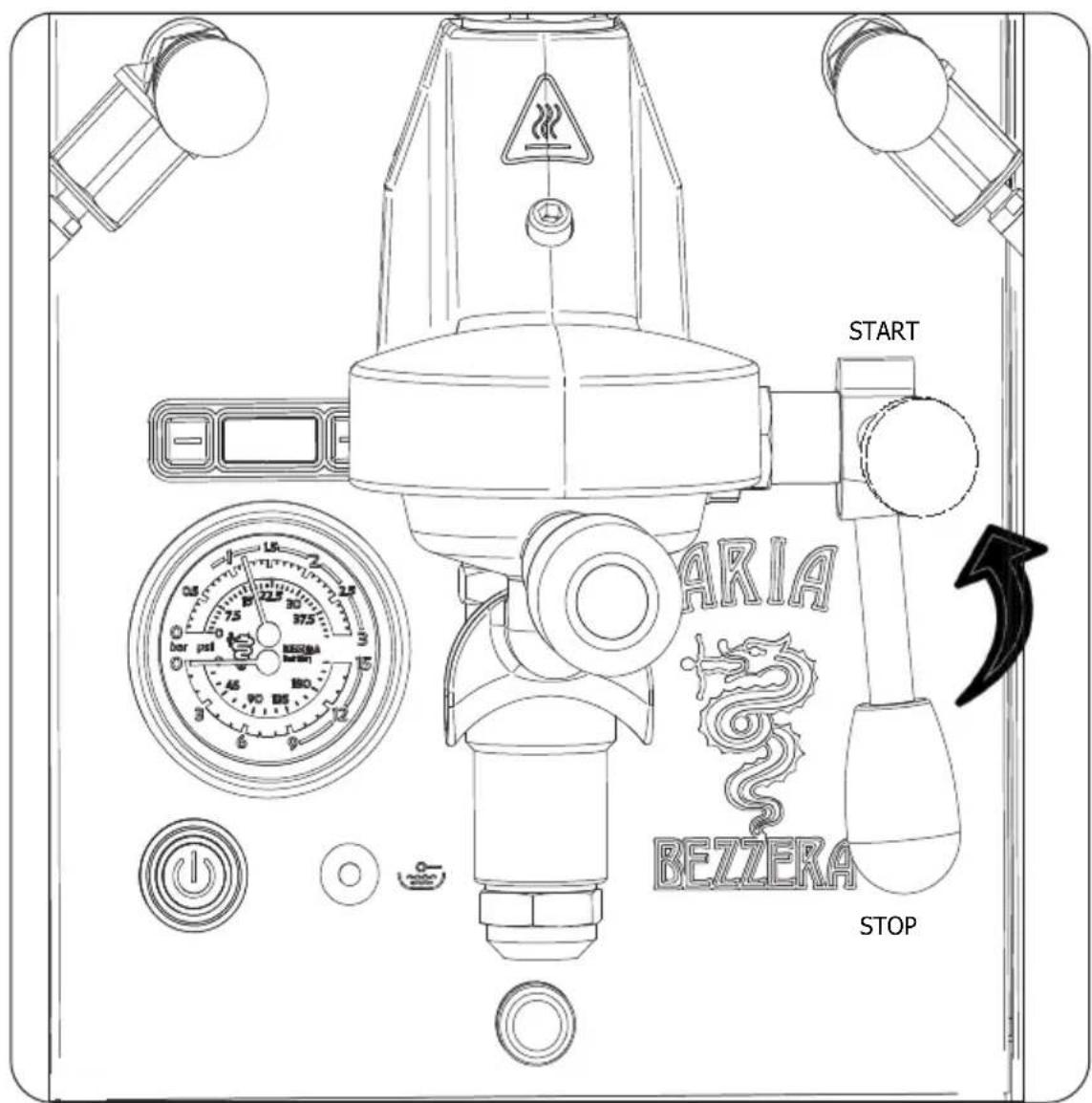
FIG. 05
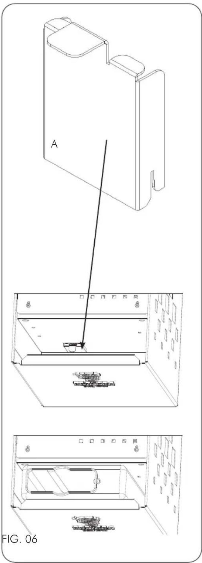
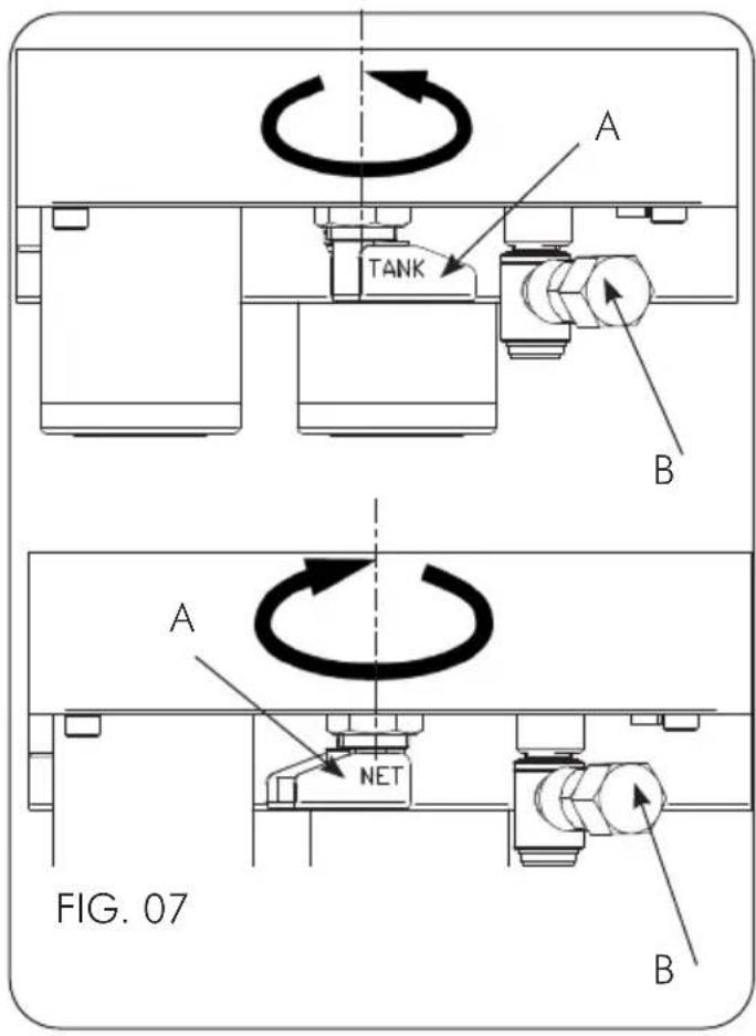
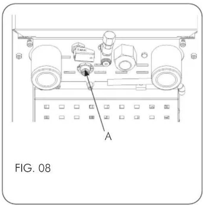
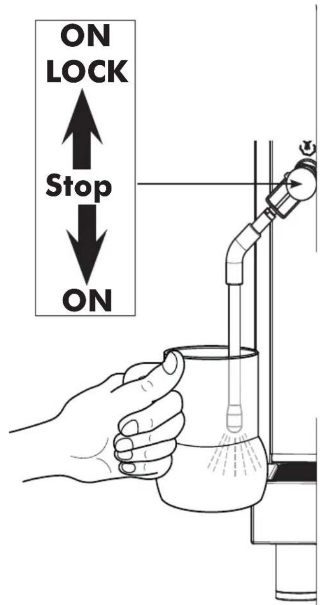
FIG. 09
natural_image
Illustration of a hand holding a camera lens with a tool, labeled 'FIG. 11' (no text or symbols on the diagram itself)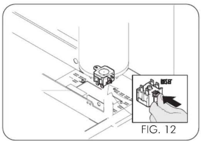
natural_image
Technical diagram showing a mechanical component being inserted into a housing, with an inset highlighting the component (no text or symbols present)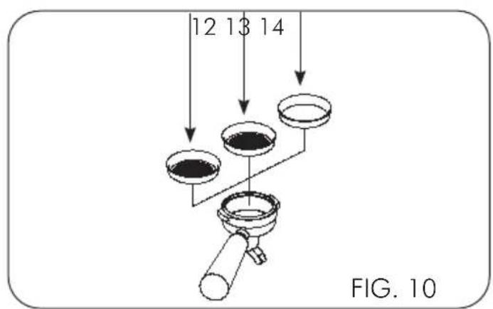
natural_image
Technical line drawing of a mechanical device with no visible text or symbols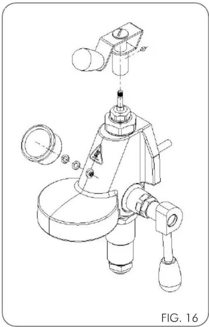
natural_image
Technical line drawing of a mechanical device with exploded view and component details (no text or symbols)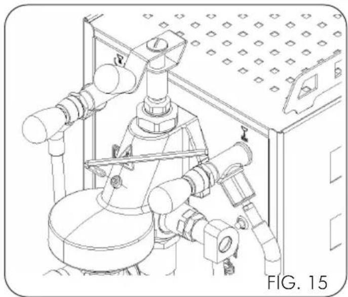
natural_image
Technical line drawing of an industrial piping system with valves and a control panel (no text or symbols)
natural_image
Technical line drawing of a mechanical device with pipes and gauges, no visible text or symbolsFIG. 18
G.BEZZERA S.R.L. warranty - Validity terms
The provided products are covered by warranty due to defects of material and/or manufacturing for a period of 12 months from the invoicing date. If the machine is outside the warranty period, it will not be possible to avail of it. Warranty will be granted only after submission of the original purchase document (sale receipt or invoice) attesting the purchase date.
In case of malfunction attributable to manufacturing defects, request the warranty intervention directly to the authorized G.BEZZERA S.R.L. dealer where the machine has been purchased, indicating the malfunction and the serial number indicated in the user manual or on the machine frame.
Goods returns which may reach the authorized dealer without the above serial number will void the warranty, since machine traceability data would not be available.
In case of return, equipment delivery is care of the customer. Handle with care and reposition the machine inside the original packing, to avoid further damage during transport. We remind that, in order to grant the warranty, the goods shall be mandatorily returned in the original packing.
The cost and the risks of machine transport to the dealer shall be borne by the customer.
Each machine is provided with an anti-tampering seal, which makes impossible to open the machine without breaking or damaging the seal. The warranty shall never be granted in case of machine with removed or damaged seal.
Warranty will be granted only after verification by the G.BEZZERA S.R.L. specialized, authorized technician, who will evaluate whether it is possible to repair the machine on site or it is necessary to ship it to the manufacturing plant. Any tampering with the machine by non authorized personnel shall void the warranty.
If the machine is received with defective or manifestly damaged packing, the customer shall promptly notice the distributor. Do not collect the goods and especially do not try to operate the machine.

The warranty explicitly does not include the defects which:
- are attributable to the use of non genuine accessories and spare parts
- are caused by thunderbolts, humidity, fire, improper power supply voltage, as well as any other damage not objectively attributable to the manufacturer.
- are ascribable to tampering with the power supply cable
- are not ascribable to manufacturing faults, but rather to the normal wear of the materials due to the proper use of the equipment (notably, calcification and wear of the parts subject to wear, e.g. seals, grinding disks)
- occur due to wrong use, negligence or carelessness in use or care (e.g. in case of non observance of the user instructions of the equipment)
- are caused by wrong installation, maintenance, or repair by non authorized persons or by damaging during transport.
For further information, or in case of issues not taken into account in the following instructions, refer to the authorized service centres.
Conditions de validité de la garantie G.BEZZERA S.R.L.
6 - USO DELLA MACCHINA
6 - USO DELLA MACCHINA
1.1 General warnings 30
1.2 Intended use.... 31
2 - MACHINE INSTALLATION....32
2.1Warnings 32
2.2 Preparation of system for installation.... 32
2.2.1 Connection to mains electricity 32
2.2.2 Water supply mode (TOP versions only) 32
2.2.3 Connection to drainage circuit 32
2.2.4 Flow regulator installation (for PID version only) 32
3 - MAINTENANCE....32
3.1 Safety rules.... 32
3.2 - Cleaning the machine 33
3.3 Safety thermostat – Manual resetting 33
3.4 Cleaning hydraulic circuits after a long period of inactivity 33
3.5 Correct disposal of the product 34
4 - TRANSPORT......34
4.1 Packaging 34
4.2 Handling the machine 34
4.3 Storage.... 34
5 - DESCRIPTION OF MACHINE ....35
5.1 Description of operating cycle 35
5.2 Description of commands 35
5.3 Technical data 35
6 - USE OF MACHINE....36
6.1 Starting the machine and filling the boiler with water 36
6.1.1. Connection to the and water mains 36
6.1.2. Connection to the and water mains (TOP versions only) 36
6.2 Heating.... 36
6.2.1. Version with PID digital temperature control 36
6.2.2. Machine heating activation 36
6.2.3. Boiler temperature adjustment 36
6.2.4. Temperature/pressure conversion table 37
6.3 Preparation of coffee 37
6.4 Coffee dispensing with flow regulator (for PID version only) 37
6.5 Pump adjustment (rotary pump versions only) 37
6.6 Steam supply 38
6.7 Extracting hot water 38
6.8 Turning off the machine 38
6.9 Pressure gauge 38
7 - TROUBLESHOOTING ....39
Problem / Troubleshooting/Solution / Advice 39
1 - WARNINGS
1.1 General warnings

- The electric and water systems must be set up by the user in accordance with chapter 4 in this "Machine installation" booklet.
- The installer cannot, under any circumstances, modify the existing system set up by the user.
- This instructions booklet represents an integral part of the machine and must be read carefully by the user before using the machine.
- Store the booklet for future consultation.
- The machine is delivered without water inside the boiler to avoid possible damage caused sub-zero temperatures.
- Make sure the electric sys- tem is earthed.
- Do not touch the machine with damp and/or
wet hands and feet.
- Do not use the machine bare foot.
- Do not connect the power cable to makeshift extension cords and similar.
- Do not disconnect the machine from the mains power by pulling the power cable.
- Do not use the machine if the power cable is rolled up.
- This appliance is not intended for use by persons (including children) with reduced physical, sensory or mental capabilities, or lack of experience and knowledge, unless they are under the supervision of a person who is responsible for their safety or they have been instructed in how to use the appliance.
- Supervise children so that they do not play with the machine.
- To avoid water getting inside the machine, place the cups on the cup warmer with the hollow side facing the top.
- The machine is not intended for outdoor use.
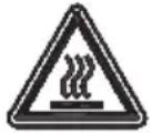
- The following symbol indicates a burn hazard.
1.2 Intended use
The ARIA/ARIA PID espresso coffee machine has been designed to make espresso coffee, to produce hot water to make tea, chamomile and other infusions, and to produce steam and heat beverages (milk, hot chocolate, cappuccino, punch, etc.).
This machine was conceived exclusively for the aforesaid uses.
All other uses are deemed improper and, therefore, prohibited by the manufacturer. The manufacturer will not be deemed liable for damage caused by the improper use of the espresso coffee maker.
2 - MACHINE INSTALLATION
2.1Warnings
Installation must be carried out by qualified personnel, according to the instructions supplied by the manufacturer and in compliance with current laws.
The machine must be positioned and installed in a place where use and maintenance are performed exclusively by qualified personnel. The machine can be used in places set up for staff kitchen areas in shops, offices and other working environments; holiday farm houses; by clients in hotels, motels and other types of accommodation; bed and breakfast settings; etc.
2.2 Preparation of system for installation
Place the machine on a flat, horizontal, even, dry, smooth, sturdy, stable surface positioned at such a height that the cup warming surface is over 150 cm from the ground.
Do not use water jets or install in places where water jets are used.
To ensure normal operation, the appliance must be installed in locations where temperatures range between +5°C and +32°C and humidity does not exceed 70%.
If the machine is exposed to temperatures below +0 °C, proceed as follows:
- ensure that the machine has spent 24 hours in a location where the temperature is above +15°C before switching it on.
The machine is powered by electricity and it needs the following to operate:
- connection to mains electricity.
2.2.1 Connection to mains electricity

Warnings:
- The connection to mains electricity must be done by qualified personnel.
- The wiring must be done in compliance with current laws and earthed.
The machine is supplied with a power cord fitted with a plug. For a permanent connection to the mains between the appliance and the mains, fit an omnipolar safety switch with a minimum opening between the contacts of overvoltage category III sized for the load that complies with the current standards.
2.2.2 Water supply mode (TOP versions only)
The machine is delivered in tank mode; to convert the supply to mains mode, follow the water supply connection instructions first (see paragraph 2.2.2)

Warnings:
The conversion from TANK mode to MAINS mode or vice-versa involves a variation of pressure, produced by the rotary pump. This pressure can be adjusted as described in section 6.5 of this manual.
2.2.3 Connection to drainage circuit
Connect a rubber hose (Fig.03 Pos.13) with an internal diameter of 10 mm from the fitting on the machine's drain to a previously prepared open siphon drain.
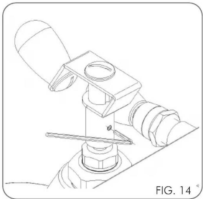
2.2.4 Flow regulator installation (for PID version only)
Before using the flow regulator, it is necessary to assemble the knob and pressure gauge supplied (Fig. 16).
Position the knob on the appropriate pin making sure that it is parallel to the knobs of the hot water and steam taps; tighten the rear screw using the spanner supplied (Fig. 15)
Unscrew the screw on the body of the dispensing group using the appropriate spanner supplied (Fig. 16) and screw in the pressure gauge using one or two gaskets to place it in the correct position
3 - MAINTENANCE
Follow the maintenance instructions indicated below to operate the machine correctly.
3.1 Safety rules
Do not use water jets on the machine. Disconnect the machine from the power line by turning the lever of the omnipolar disconnecter, of the electric mains, to the "0" rest position, remove the plug and close the water interception valve before carrying out maintenance and/or cleaning operations. If the machine malfunctions, do not attempt to repair it yourself and immediately contact tech-
nical support. In case of damage to the power supply cord, turn off the machine immediately, close the water and contact the technical assistance service. Avoid replacing it autonomously. Perform cleaning/maintenance with the machine cold, preferably wearing protective gloves.
3.2 - Cleaning the machine

Warnings: For the best results and in compliance with current regulations, change the water in the boiler and pipes when starting the machine every day.
This advice is for indication purposes only: maintenance and cleaning schedules depend on the use of the machine.
After each use
1) Clean the steam wand.
2) Clean the filter-holder and filters.
Daily
1) Clean the cup rack and drip tray.
2) Clean the bodywork.
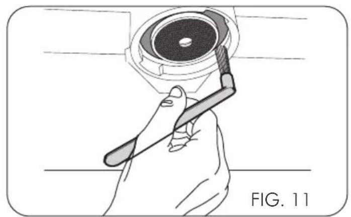
3) Clean the group gasket with the brush supplied.
4) Wash the group as follows: clip the filter holder with the blind filter supplied to the group and start a delivery several times.
5) Immerse the filter-holders and filters in boiling water for a few minutes to any coffee oils and use a cloth or sponge to remove it.

For washing and cleaning, do not use solvents, detergents or abrasive sponges. Only use specific products for coffee machines.
Wash the bodywork using a cloth soaked in water and/or neutral detergent, taking care to dry the surface well before reconnecting the machine to the mains electricity. Use water to wash the cup rack and the drip tray.
To wash the tank after having extracted it, use water and neutral detergents and perform thorough rinsing. Reinsert the tank and reinsert the silicone tubes, ensuring that the suction tube reaches the bottom.
3.3 Safety thermostat – Manual resetting

Caution! The operation described below must be only performed by an installation technician authorised by the manufacturer.
During machine operation the overheating of the resistance in the boiler can trig, disconnecting the power, the safety thermostat that prevents the occurrence of more damages to the boiler. To restore normal operation, it is necessary to solve the fault that has caused the intervention of the safety thermostat and then restore the normal condition by pressing the red button (RESET) (Fig. 12).
3.4 Cleaning hydraulic circuits after a long period of inactivity
Once the hydraulic/electrical installation has been completed, carry out a complete rinsing cycle following the operations described in points A and/or B.
Warnings: for use of the machine controls (valves, dispensing group, switches, etc.) refer to the relative sections contained in this manual.
The introduction into the tank of chemicals, descaling agents, vinegar and/or even citric acid, even if diluted, compromises the life of the machine components. Any product used that is not fresh water will automatically void any warranty. Use ideal hardness drinking water, in French degrees approximately 15^ F; never use hot water.
A - Upon initial ignition or after a prolonged period of inactivity of the machine (approximately 7 days)
1) Switch on the machine, fill the boiler with water and heat as described in paragraph 5.
2) Wait 12 hours.
3) Perform dispensing for at least 30 seconds with the filter-holder connected but without coffee to allow the exchange of water in the exchanger (lever machines need coffee inside the filter-holder).
4) Switch off the machine and completely drain the water from the boiler by operating the water and steam tap into a heat-resistant container with a capacity of at least 1 litre.
Ensure that:
- there is always fresh water in the tank (where required).
- do not re-use the water drained during rinsing.
B - After a stop of at least 4 hours
1) Dispense water from the respective tap for 5 seconds.
2) Perform dispensing with the filter-holder connected but without coffee for at least 15 seconds.
3.5 Correct disposal of the product
(electric and electronic waste)
(Applicable in the countries of the European Union and in those with waste sorting systems)
The label affixed on the product and on the documents indicates that the product must be disposed of with other domestic waste at the end of its life cycle. To avoid any damages to the environment or health caused by improper waste disposal, the user must separate this product from other types of waste and recycle it responsibly to promote the sustainable reuse of material resources.
Domestic users should contact the reseller from whom they purchased the product or the relevant office in their area to obtain all information about waste sorting and recycling of this type of product. Corporate users should contact their supplier to check the terms and conditions of the purchase agreement.
This product must not be disposed of with other industrial waste.
4 - TRANSPORT
4.1 Packaging
The ARIA/ARIA PID espresso coffee machine, previously protected with cardboard, is packed in cardboard boxes.

Warnings:
- After removing the machine from the packaging, check that it is intact and all the parts have been supplied.
- The packaging must never be left within reach of children and must be disposed at designated waste facilities.
- If any damage to the machine is detected or if any parts are missing, do not use the machine and immediately notify the local dealer.
4.2 Handling the machine
The espresso coffee machine can be handled with pallet truck or lift truck, or manually.
4.3 Storage
The correctly packed machine must be stored in a dry location with a temperature between +5°C and +30°C and relative humidity not exceeding 70%. Do not stack more than four boxes on top of each other.
5 - DESCRIPTION OF MACHINE
5.1 Description of operating cycle
Water comes from the tank at the back of the machine via a rotary pump, passes through a pressure relief valve set at 12 bar (1.2 MPa) and allows the boiler and exchanger to be filled. The water of the boiler, which is heated by a resistor, heats the water in the heat exchanger, from which, by means of a dip tube, it is sent to the group through a manually controlled valve that allows the passage of the water for the infusion of the coffee.
5.2 Description of commands
(Fig. 01)
1 Main switch
2 White indicator light
3 Coffee dispensing lever
4 Group head
5 Filter holder
6 Steam knob
7 Steam wand
8 Hot water knob
9 Hot water wand
10 Pressure gauge
11 Power supply cable
(Fig. 10)
12 1 cup filter
13 2 cup filter
14 Blind filter
(Fig. 03)
12 Front unloading
13 Basin unloading
14 PID display
5.3 Technical data
(Fig. 02)
| Power supply V~/Hz 220 - 240V~ | / 50-60Hz 110 | 0 - 120V~ / 50-60Hz | |
| Heating element V~ 220 - 240 120 | |||
| Nominal power W 1200 - 1400 1300 | |||
| Heating element W 1100 - 1300 1200 | |||
| Boiler lt 1.5 | |||
| Tank (S) | lt 3.0 | ||
| Width ‘A’ | mm | 250 | |
| Depth ‘B’ | mm | 425 | |
| Height ‘C’ | mm | 411 | |
| Net weight | kg | 19 | |
| Gross weight (box) | kg | 22 | |
6 - USE OF MACHINE
6.1 Starting the machine and filling the boiler with water
6.1.1. Connection to the water mains
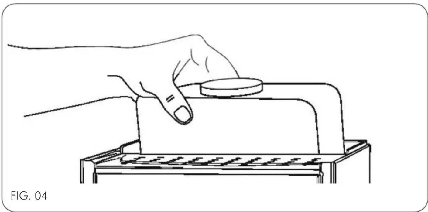
Introduce water into the tank, ensuring that the suction pipe reaches the bottom (Fig. 04).

Warnings:
- Use ideal hardness drinking water, in French degrees approximately 15^ F; never use hot water.
- Check that the tap located in the lower part of the machine (Fig. 07, Pos. A) is turned to "TANK" mode
6.1.2. Connection to the water mains (TOP versions only)
In case of conversion from tank supply to water mains supply before opening the water shut-off valve upstream of the machine connection, remove the tank and insert the plug (Fig. 06) in the tank support opening where the tank water level detection sensor is located.
Turn the tap located in the lower part of the machine (Fig. 07, Pos. A) to "NET" mode
Make sure that the water supply line is connected to a drinking water network with operating pressure between 0 and 6 bar (0 - 0.6 MPa).
If the water network has pressures above 6 bar (0,6 MPa), install a pressure reducer.
Install a water shut-off valve upstream of the machine's connection.
The water inlet pipe (Fig. 07, Pos. B) is supplied G 1/8" thread.
Insert the plug into the electrical socket.
Press the switch (Fig.01; pos.1 Fig.03; pos. 1) checking that the indicator light turns on; the boiler is filled with water automatically.

safety device will halt motor pump operation after 120 seconds if the maximum water level in the boiler is not reached.
To restore operation, simply switch the machine off and on again.
6.2 Heating
For the machine to reach the correct temperature, with the pressure indicated on the boiler pressure gauge (Fig. 01; pos. 10; Fig. 03; pos. 10) between 1 and 1.2 bar (0.1 - 0.12 MPa), open the steam tap (Fig. 01; pos. 6; Fig. 03; pos. 6) and release the steam into the drip basin 2 or 3 times. If the white indicator light is on, water is in the tank; if it is off, no water is present in the tank.
6.2.1. Version with PID digital temperature control
The coffee machine with temperature control has a digital temperature regulator which can adjust the temperature from 80 °C to 100 °C. This adjustment allows the boiler pressure to be changed from a minimum of 0.5 bar to a maximum of 1.7 bar.

Never raise the boiler temperature above 100°C. The subsequent increase in pressure could trigger the safety valve.
6.2.2. Machine heating activation
Press the mains switch (Fig. 03, Pos. 01) to power up the machine, the temperature control display (Fig. 03; pos. 14) will display "OFF", i.e. the boiler heating element is off.
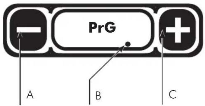
To activate boiler heating, press the key (Fig. 18; pos. C), the temperature detected in the boiler will be displayed.
A dot in the lower right corner of the display shows that the heating element is on. (Fig. 18; pos. B).
6.2.3. Boiler temperature adjustment
Adjusting the boiler temperature is a personal factor which depends on a number of variables, such as external temperature, humidity, coffee quality, etc. and is set in the factory to an average temperature of 90 °C.
By pressing the key (Fig. 18; pos. A) the display will show PrG; press the key (Fig. 18; pos. C) to display the boiler temperature set by the factory at 90°C, which corresponds to a pressure of 1 bar; at this point, the set temperature can be changed using the keys (Fig. 18; pos. A\C).
The temperature check, 3 seconds after pressing the last key, stores any changes and displays the boiler temperature again.
6.2.4. Temperature/pressure conversion table

Warnings:
The machine allows you to choose which unit of measurement of temperature is displayed:
^ C (degrees Centigrade).
°F (degrees Fahrenheit).
To set a value press the key (Fig. 18; pos. A) the display will show PRG; press the key again (Fig. 18; pos. A) the display will show UoM; press the key (Fig. 18; pos. C) to change the unit of measurement of temperature using the keys (Fig. 18; pos. A/C).
| °C°F | 80176 | 85185 | 90194 | 95203 | 100212 |
| bar 0.5 | 0.7 | 1.0 | 1.3 | 1.7 |
6.3 Preparation of coffee
1) Remove the filter holder (Fig. 01; pos. 5; Fig. 03; pos. 5) from the group head (Fig. 01; pos. 4; Fig. 03; pos. 4).
2) Fill the filter holder with ground coffee and press the coffee in, taking care not to soil the edge of the filter holder.
3) Reattach the filter holder to the group (Fig. 01; pos. 4; Fig. 03; pos. 4).
4) Place the cup under the coffee dispensing spout.
5) Raise the coffee dispensing lever (Fig. 01; pos. 3; Fig. 03; pos. 3; Fig. 05) until the desired amount of coffee is obtained.
6) Lower the coffee dispensing lever (Fig. 01; pos. 3; Fig. 03; pos. 3; Fig. 05) to stop dispensing.
NOTE: While dispensing coffee, the display (PID version only) will feature a stopwatch indicating the duration of the dispensing process.

Warnings:
- Do not remove the filter holder when the appliance is in operation; the group head is under pressure.
- Do not touch the metal part of the filter holder directly as it is hot.
- The standard doses for the filters are 10 grams for one dose and 20 grams for two doses.
6.4 Coffee dispensing with flow regulator (for PID version only)
The flow regulator, where present, allows for the dispensing pressure to be changed (it is always less than or equal to the set pump pressure. See paragraph 6.5).
Turn the adjustment knob (Fig. 18):
- Clockwise to decrease the dispensing pressure - Counter-clockwise to increase the dispensing pressure
1) Remove the filter holder (Fig. 01; pos. 5; Fig. 03; pos. 5) from the dispensing group (Fig. 01; pos. 4; Fig. 03; pos. 4).
2) Load the filter-holder with ground coffee, press the coffee taking care not to make the edge of the filter-holder dirty.
3) Reattach the filter holder to the group (Fig. 01; pos. 4; Fig. 03; pos. 4).
4) Place the cup under the coffee dispensing spout.
5) Raise the coffee dispensing lever (Fig. 01; pos. 3; Fig. 03; pos. 3; Fig. 05) until the desired amount of coffee is obtained.
6) During dispensing, it is possible to turn the flow regulator knob (Fig. 17)
7) Lower the coffee dispensing lever (Fig. 01; pos. 3; Fig. 03; pos. 3; Fig. 05) to stop dispensing.
6.5 Pump adjustment (rotary pump versions only)
Once the preferred water supply mode has been chosen, it is possible to vary the working pressure, bringing it back to 9 bar (0.9 MPa) calibrated in the factory, by screwing or unscrewing the adjustment fitting located in the lower part of the machine (Fig. 08, pos. A).
Do the following:
1) Insert the filter-holder with a blind filter (Fig. 10; pos. 14) into its slot.
2) Raise the coffee dispensing lever to the horizontal position (Fig. 01, Pos. 3 and Fig. 03, Pos. 03), take note of the pressure shown on the pressure gauge (Fig. 13, Pos. B) and turn the coffee dispensing lever back to the vertical position.
3) Tighten the pump adjustment screw (Fig. 08, pos. A) to increase the pressure or unscrew to decrease it, performing no more than one complete turn at a time.
Repeat steps 2 and 3 until returning the pressure
exerted by the pump during dispensing to 9 bar (0.9 MPA) or in any case between 8 and 10 bar (0.8 and 1.0 MPa).

Warning:
- Do not remove the filter-holder with closed filter while the machine is dispensing.
- Do not adjust the pump pressure above 11 bar (1.1 MPa).
6.6 Steam supply
(Fig. 09)
1) To prevent the liquid from being sucked back into the boiler, release the steam by turning the knob (Fig. 01; pos. 6; Fig. 03; pos. 6).
2) Insert the steam wand (Fig.01; pos.7; Fig.03; pos.7) in the container of the liquid to be heated.
3) Press and hold the steam tap knob (Fig. 01; pos. 6; Fig. 03; pos. 6), lifting the lever the tap will remain open (Fig. 09). The amount of steam dispensed depends on how far the tap is opened: the further the tap is opened, the greater the amount of steam dispensed.
4) Once the steam has been dispensed, release the knob, remove the liquid container and immediately clean the steam nozzle with residues of the heated liquid with a damp cloth.
Warning:
Do not touch the steam wand directly because it is hot.
6.7 Extracting hot water
1) Place the container under the hot water wand (Fig. 01; pos. 9; Fig. 03; pos. 9).
2) Press and hold the water tap knob (Fig. 01; pos. 8) to dispense the required amount of water.
3) Once the water has been dispensed, release the knob.
Warning:
Do not touch directly the water spout because it is hot.
6.8 Turning off the machine
Press the switch (Fig. 01; pos. 1; Fig. 03; pos. 1) and check that the indicator light goes out.
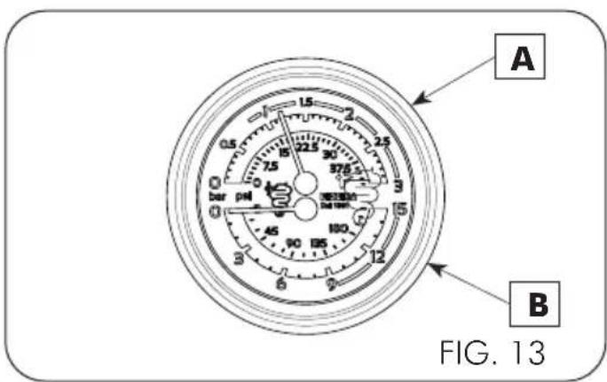
6.9 Pressure gauge
(Fig. 13)
The machine has a double scale pressure gauge that can control the following pressure:
Boiler pressure gauge (Fig. 13 - A)
scale 0\~3 bar (0\~0,3 MPa)
Indicates the normal working pressure of the boiler.
Pump pressure gauge (Fig. 13 - B)
scale 0\~15 bar (0\~1.5 MPa)
The pressure gauge indicates the maximum pump pressure during operation. When the pump is stationary, the pressure gauge indicates "0" if in TANK mode; in MAINS mode, it indicates the mains pressure.
7 - TROUBLESHOOTING
Problem Troubleshooting/Solution Advice
| No steam output from the wand | The tip of the steam wand is clogged; unclog it with needle. This problem is caused by the way the spout is inserted into the milk. | Clean the steam spout after each use. |
| Leaks from filter holder | Possible causes:1- The group head gasket is worn or encrusted.2- The filter holder is incorrectly inserted in the group. | Clean it using the brush supplied.Should the problem occur again, call a specialised technician |
| Difficulty in positioning the filter holder on the clamping ring | The problem can be caused by an excessive dose of coffee in the filter holder. | Decrease the quantity of coffee in the filter holder. (Standard doses for filters are 10 g per dose). |
| Incorrect position of the filter holder once inserted in the group | Once inserted on the group, the handle of the filter holder has shifted to the right. The group head gasket is worn. | Call a specialised technician to replace the group head gasket. |
| The flow of coffee is scarce | The coffee is dispensed drop by drop, the output time is too long and the quality of it is not good, the cream is dark.Possible causes:1- The coffee is ground too finely.2- The coffee has been pressed too firmly in the filter holder.3- The dose in the filter holder is excessive.4- The group shower head is clogged.5- The filter in the filter holder is clogged. | In cases 1-2-3, the problem may be resolved by correctly adjusting the grinding and/or dosing of the coffee.In case 4, contact a technician.In case 5, clean the filter or replace it. |
| The flow of coffee is excessive | The coffee is dispensed too quickly and the cream is lighter than usual.Possible causes:1- The coffee is ground too coarsely.2- The coffee in the filter holder has not been pressed firmly enough.3- The dose in the filter holder is too small. | Adjust the grinding and/or dosing of the coffee. |
Problem Troubleshooting/Solution Advice
| The coffee dispensed is too cold | Possible causes:1- The filter holders are cold.2- The coffee is ground too finely.3- The machine water circuit is dirty (lime-scale).4- The boiler pressure is lower than 0.8 bar (0.08 MPa). | In case 1, keep the filter holder mounted on the group.In case 2, adjust the grinding of the coffee.In cases 3 and 4, call a specialist technician. |
| The coffee dispensed is tepid | The coffee dispensed is tepid even if the pressure is normal, between 1 and 1.2 bar (0.1 – 0.12 MPa). In this case, the pressure detected is false. | Call a specialised technician to check the bleed valve. Meanwhile, to use the machine, open the steam tap (Fig. 01; pos. 9), the boiler pressure will drop to zero, which will cause the heating element to engage and the temperature to rise. Perform this operation daily when turning on the machine. |
| The coffee dispensed is too hot | Possible causes:1- The boiler pressure is higher than 1.3 bar (0.13 MPa).2- The machine is covered by something that prevents it from cooling.3- The machine was installed in a position that does not allow air circulation. | In case 1, call a specialised technician.In the cases 2-3, reset the machine cooling conditions. |
| Coffee deposits on the bottom of the cup | Possible causes:1- The coffee is ground too finely.2- The filter holder is dirty on the inside or the filter is damaged.3- The grinding discs are worn. | Case 1 can be solved by adjusting the grinder correctly.In case 2, clean the filter holder or replace the filter.In case 3, a technician needs to be contacted. |
Index
1 - AVERTISSEMENTS......42
natural_image
Abstract red line drawing of a stylized snake or serpent (no text or symbols)BEZZERA
Dal 1901
G.BEZZERA S.R.L.
MACCHINE PER CAFFE' ESPRESSO
Via Luigi Bezzera,1
20088 Rosate - Milano - Italy
Tel. ++39 02 90848102 r.a. - Telefax ++39 02 90870287
Web: www.bezzera.com
e-mail: admin@bezzera.it