ROYAL 15 E 38 - Scrubber Ghibli & Wirbel - Free user manual and instructions
Find the device manual for free ROYAL 15 E 38 Ghibli & Wirbel in PDF.

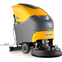
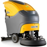
| Product type | Walk-behind floor scrubber |
| Brand | Ghibli & Wirbel |
| Model | ROYAL 15 E 38 |
| Power supply | Version E: 100-240 V~, 50/60 Hz ; Version BC: Lithium battery 24 V, 312 Wh or 547 Wh |
| Installed power | 470 W |
| Washing width | 385 mm |
| Suction width | 477 mm |
| Solution tank capacity | 15 L |
| Recovery tank capacity | 17 L |
| Dimensions (L x W x H) | 772 x 477 x 731 / 1122 mm |
| Empty weight | 44 kg - 45.4 kg depending on version |
| Weight in working order | 63 kg - 65.6 kg |
| Battery life (BC version) | 1 h (312 Wh) / 2 h (547 Wh) |
| Brush rotation speed | 130 rpm |
| Specific brush pressure | 52 g/cm² |
| Suction depression | 140 mbar (1427 mmH₂O) |
| Suction air flow | 21 L/s |
| Noise level | 64 dB(A) (silent mode 61 dB(A)) |
| Electrical protection | IPX3 |
| Operating temperature | 5 °C to 40 °C |
| Maximum traversable slope | 2 % |
| Main functions | Washing, brushing, drying; 5 work cycles; ECO mode; automatic stop |
| Routine maintenance | Drain and clean tanks after each use; clean suction unit and squeegee blades |
| Safety | Operator presence lever; automatic stop after 5 min of inactivity; error alarms |
| Spare parts | Brushes, squeegee blades, lithium batteries, fuses |
Frequently Asked Questions - ROYAL 15 E 38 Ghibli & Wirbel
User questions about ROYAL 15 E 38 Ghibli & Wirbel
0 question about this device. Answer the ones you know or ask your own.
Ask a new question about this device
Download the instructions for your Scrubber in PDF format for free! Find your manual ROYAL 15 E 38 - Ghibli & Wirbel and take your electronic device back in hand. On this page are published all the documents necessary for the use of your device. ROYAL 15 E 38 by Ghibli & Wirbel.
USER MANUAL ROYAL 15 E 38 Ghibli & Wirbel


49.0321.00
ed. 06/2024
UK Use and Maintenance
natural_image
Line drawing of a cleaning or cleaning service vehicle with a vertical pole and wheels (no text or symbols)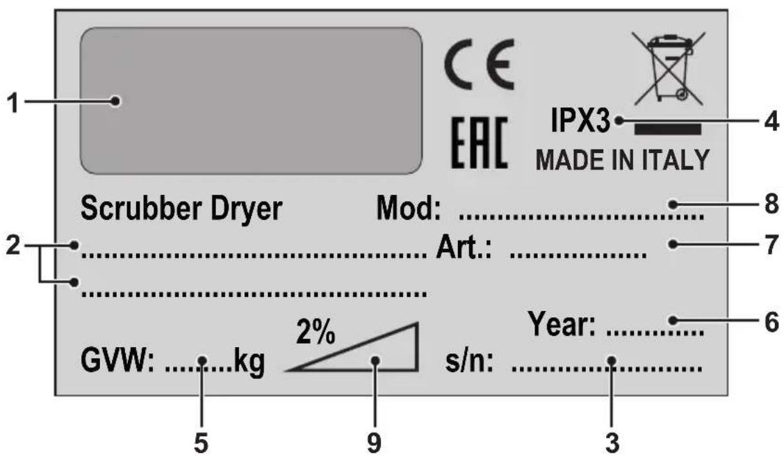
| 1 2 3 | |||
| IT | Produttore Caratteristiche elettriche N° Matricola | ||
| UK | Manufacturer Electrical characteristics Serial N° | ||
| FR | Producteur Caractéristiques électriques N° Matricule | ||
| DE | Hersteller Elektrische Eigenschaften Serien-Nr. | ||
| ES | Fabricante Características eléctricas N° Matrícola | ||
| PT | Produtor Características elétricas Número de série | ||
| NL | Producent Elektrische eigenschappen Serienummer | ||
| CS | Výrobce Elektrické údaje Výrobní č. | ||
| RU | Изготовитель | Электрические характеристики | Заводской No |
| PL | Producent Specyfikacja elektryczna Numer seryjny | ||
| AR | الصنع | المواصفات الكهربائية | الرقم التسل스لي |
(Translation of original instructions)
FR Français ....FR - 1
100% 70% 50% 30% 10% 0%


Dear Customer, Thank you for choosing one of our cleaning products.
The floor scrubber dryer that you have purchased has been designed to satisfy the user in terms of ease of use and reliability over time.
We are aware that in order for a good product to stay that way, over time, it requires continuous updates aimed at meeting the expectations of those who use it on a daily basis. For this reason, we hope that you will not only be a satisfied customer but also a partner who does not hesitate to give us your opinions and ideas originating from your personal day-to-day experience.
INDEX
INDEX 2
TECHNICAL DATA....3
1.1 - INTRODUCTION......4
2.1 - GETTING TO KNOW THE MACHINE (Fig. A)......4
3.1 - UNPACKING......4
3.1.a - Preliminary operations (Fig. B) 4
3.1.b - Positioning of the handle (Fig. B) 5
3.1.c - Unloading the machine from the wooden pallet (Fig. B)....5
4.1 - ASSEMBLY COMPONENTS....5
4.1.a - Brush installation (Fig. C) 5
4.1.b - Squeegee installation (Fig. D) 5
4.1.c - Battery connection (for Lithium version)....6
4.1.d - Electrical connection (for cord version) (Fig. E)....6
5.1 - CHARGING THE BATTERY (Fig. F) 6
6.1 - MACHINE CONTROLS 7
6.1.a - Control panel (Fig. A)....7
7.1 - DISPLAY 8
8.1 - MACHINE HANDLING (Fig. A) 9
9.1 - DETERGENT SOLUTION TANK....9
9.1.a - Tank filling (Fig. G)....9
10.1 - OPERATION 9
10.1.a - Checks before use (Fig. A)....9
10.1.b - Preparing the machine and choosing the cycle (Fig. A) 9
10.1.c - Using the machine (Fig. A) 10
10.1.d - End of use and switching off (Fig. A)....10
10.1.e - Parking the machine (Fig. A) 10
11.1 - DRAINING THE RECOVERY WATER (Fig. H) 11
12.1 - MAINTENANCE AND CLEANING 11
12.2 - OPERATIONS TO PERFORM DAILY 11
12.2.a - Emptying and cleaning the detergent solution tank (Fig. G).... 11
12.2.b - Cleaning the recovery water tank (Fig. H-I).... 12
12.2.c - Squeegee cleaning (Fig. J).... 12
12.3 - OPERATIONS TO PERFORM WEEKLY 12
12.3.a - Cleaning the solution filter (Fig. G)....12
12.4 - OPERATIONS TO PERFORM WHEN NECESSARY.... 12
12.4.a - Brush cleaning / replacement (Fig. C) 12
12.4.b - Squeegee rubber blades cleaning / replacement (Fig. K) 13
12.4.c - Squeegee incidence set up (Fig. K) 13
12.4.d - Lithium battery replacement (Fig. M).... 13
13.1 - PARAMETER SETTING (Fig. A).... 14
13.1.a - OPERATOR parameters.... 14
14.1 - FUSE CHECK/REPLACEMENT.... 15
15.1 - ALARMS DURING THE FUNCTIONING....16
16.1 - TROUBLESHOOTING....17
17.1 - DEMOLITION OF THE MACHINE.... 18
18.1 - WIRING DIAGRAM.... 18
18.1.a - Wiring diagram (E version)....19
18.1.b - Wiring diagram (BC version) 19
TECHNICAL DATA
| ROYAL 15 E - BC - BC PLUS | |
| Driving type Walk behind | |
| Features | |
| Operation power (cord) Power supply 100-240 V~ 50/60 Hz | |
| Operation power (24V Lithium battery) 312 Wh - 547 Wh | |
| Supply power 24V dc | |
| Installed power 470 W | |
| Running time 1 h (312 Wh) - 2 h (547 Wh) | |
| Washing track width 385 mm | |
| Suction width 477 mm | |
| Productivity theoretical / practical 1540 m | ^2/h / 924 m^2/h |
| Hand-arm vibration system 1,0 m/s | ^2 |
| Sound pressure (LpA) 64 dB(A) | |
| Sound pressure in silent mode 61 dB(A) | |
| Uncertainty KpA 0,75 dB(A) | |
| IP code | IPX3 |
| Operating temperature | 5°C ÷ 40°C |
| Brush | |
| Diameter / pad / number | 385 mm / 15" x 1 |
| Motor power / number | 280 W x 1 |
| Brush speed | 130 rpm |
| Specific pressure | 52 g / cm ^2 |
| Traction | |
| Forward movement | Manual |
| Maximum slope of use during work | 2 % |
| Suction | |
| Motor power | 150 W |
| Depression (water column) | 140 mbar / 1427 mmH _2 O |
| Air flow | 21 l / s |
| Tank | |
| Typology | Double tank |
| Recirculation | No |
| Solution capacity | 15 l |
| Recovery capacity | 17 l |
| Dimensions | |
| Machine dimensions (length x width x height) | 772 x 477 x 731 / 1122 mm |
| Machine width - Brush deck | 392 mm |
| Machine width - squeegee | 477 mm |
| Battery compartment dim. (length x width x height) | 154 x 233 x 134 mm |
| Weight | |
| Empty weight 44 kg - 45 kg - 45,4 kg | |
| Weight with power supply / battery 46 kg - 47,2 kg | - 48,6 kg |
| Gross vehicle weight (GVW) 63 kg - 65,6 kg - 65,6 kg | kg |
1.1 - INTRODUCTION

NOTE:
The numbers and the figure references shown in brackets refer to the components indicated in the annexed illustrative sheet.

DANGER:
Before using the machine carefully read the "Safety instructions for scrubber dryer machine" manual annexed to this one.
2.1 - GETTING TO KNOW THE MACHINE (Fig. A)
(1) Driving handle.
(2) Control console.
(3) Squeegee operating pedal.
(3a) Pedal position for squeegee raised.
(3b) Pedal position for squeegee down.
(4) Operator presence lever.
(5) Lever for rotating handle positions.
(6) Recovery water tank.
(7) Recovery water tank cover.
(8) Detergent solution tank.
(9) Right door with socket and battery charger cable housing (BC version). Right door with power plug (E version).
(10) Left door for loading the detergent solution tank.
(11) Rear door for access to the recovery water discharge hose and squeegee water suction hose.
(12) Wheels.
(13) Brush deck.
(14) Brush.
(15) Squeegee group.
(16) Squeegee rubbers.
(17) Squeegee wheels.
(18) Squeegee bumper.
(19) Detergent solution valve.
(19a) Open valve.
(19b) Closed valve.
(20) Cleaning solution filter.
(21) Detergent solution drain valve.
(21a) Closed valve.
(21b) Open valve.
(22) Display.
(23) Main button/brush rotation.
(24) Brush release button.
(25) Cleaning solution button.
(26) Vacuum system button.
(27) ECO button.
3.1 - UNPACKING
3.1.a - Preliminary operations (Fig. B)
Once the packaging has been removed as indicated in the instruction sheet on the packaging itself, check the integrity of the machine and all the components supplied. If any obvious damage is found, contact your local dealer and carrier within 3 days of receipt.
- Remove the bag and boxes (28) containing the supplied accessories:
(14) 1 brush.
(15) Squeegee group.
- Take the documentation from the appropriate envelope.
(29) Machine use and maintenance manual and Safety instructions for scrubber dryer machine.
(30) Battery charger instruction manual (only for BC version).
(31) Lithium battery instruction manual (only for BC version).
- Accessories supplied only for E version:
(32) Cord with snap hook.
(33) Tear-proof hook.
(34) 15 m extension cable.
3.1.b - Positioning of the handle (Fig. B)
- Unlock the driving handle (1) by pulling one of the levers (5) and lift it positioning it at the desired angle.
- Release the lever (5) to lock the handle in position.
3.1.c - Unloading the machine from the wooden pallet (Fig. B)
- Remove the wooden blocks (35) positioned in front of the wheels.
- Turn the ramp (36) in front of the wooden pallet.
- With the help of your hands on the driving handle (1), slightly raise the front of the machine body, then carefully get off the pallet.
4.1 - ASSEMBLY COMPONENTS
4.1.a - Brush installation (Fig. C)
- Lift the machine in front by levering the handle grips (1) and remove the cardboard support (37).
- Place the brush (14) on the ground.
-
Place the brush deck (13) on top of the brush (14) so that the driving flange (38) is centered with the brush engagement hole.
-
Press the button (23) to start the machine.
- Check the "noon on the display (22),
otherwise press the button (23) again.
- Press the levers (4) to start the rotation of the brush until you hear the "CLICK" of the brush attachment, then release the levers (4).
- Press the button (23) 📄 for 3 sec. to turn off the machine.

WARNING:
Use only brushes provided by the manufacturer according to the model of the machine.
Using other types of brushes may compromise the safety of the machine.
4.1.b - Squeegee installation (Fig. D)
- Lower the squeegee support using the pedal (3) to position (3b).
- Manually rotate the brush deck (13) to one side of the machine.
- Mount the wiper (15) on the two slots of the support (37), then tighten the two handwheels (38).
- Reposition the brush deck unit in line with the machine.
- Lift the squeegee assembly using the pedal (3) into position (3a).

WARNING:
Before lifting the squeegee unit, make sure that it is in line (A) with the running direction of the machine.
In case the pedal has locked the system (B), rotate the brush deck unit outwards, press the pedal back into position (3b Fig. A) and align the brush deck unit with the machine direction, then press the pedal into position (3a Fig. A).
4.1.c - Battery connection (for Lithium version)

NOTE:
The machine is delivered with the battery already installed, connected and with a percentage charge for initial use.
To recharge or replace it, see the specific chapter and paragraph.
4.1.d - Electrical connection (for cord version) (Fig. E)
- Mount the carabiner lanyard (32) on the handle (1) of the machine.
- Insert the extension cable (34) into the anti-tear hook (33), locking it as shown in the figure.
- Secure the snap hook (33) to the carabiner (32).
- Open the right door (9) and connect the plug (41) of the machine to the socket (42) of the extension cable (34).
- Connect the power plug of the extension cord to a socket with a minimum capacity of 10A.

WARNING:
Make sure that the mains system is equipped with an RCD (circuit breaker).
Unwind the power supply extension cable completely before operating the appliance.
Use the electric extension cable only if in perfect condition.
Never let the power cable run over sharp edges and do not tread on it.
5.1 - CHARGING THE BATTERY (Fig. F)

DANGER:
Charge the batteries in well-ventilated areas which comply with standards in force in the country of use.
For safety-related information, follow what is described in chapter 1.1 of this manual.

WARNING:
For information and warnings about the battery and the battery charger, follow what is described in the battery and battery charger manual enclosed with this document.
Check that the mains voltage is compatible with the operating voltage of the battery charger.

NOTE:
Charge the battery at each end of work or whenever the battery symbol on the display (22 Fig. A) displays 10% residual charge.
With the lithium battery it is possible to carry out partial recharges.

- Bring the machine to the vicinity of a mains power outlet.
- Open the right door (9), retrieve and unwind the charger cable (43).
- Connect the cable terminal (44) to the machine socket (45), then connect the plug (46) to the mains socket (the mains voltage and frequency must be equal to the corresponding values of the charger, shown on the license plate of the machine).

NOTE:
When the battery charger is connected to the electrical mains, all machine functions are automatically disabled.
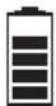
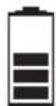
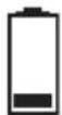
- On the display (22 Fig. A), while the battery is charging, the battery icon appears with the segments in sequence.
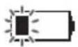
Battery with 1 flashing notch: first charging phase.

Battery with 1 fixed notch and second flashing: second charging phase.

Battery with 2 fixed notch and third flashing: fully charged battery, with control in progress by the battery charger (can last up to 40 minutes).
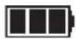
Battery with 3 fixed notch: fully charged battery.
- Once the charging cycle has finished, disconnect the plug (46) of the battery charger cable (43) from the mains and the terminal (44) from the machine socket (45), rewind it by placing it in the appropriate seat (47), then close the right door (9).
- The machine can also be used while the battery charger is being checked.
6.1 - MACHINE CONTROLS
6.1.a - Control panel (Fig. A)
(22) Display
- See the specific chapter.

in button / brush rotation
- Press to turn on the machine; at startup, the display (22) indicates the working hours of the machine, then displays the battery charge status and the amount of cleaning solution set.
- Check the "button" on the display, otherwise press the button (23) again.
- The start of the brush rotation is enabled by the levers pressed (4).
- To turn off the machine, press for 3 seconds the button (23)

NOTE:
The machine switches off automatically after 5 minutes of inactivity, press the button (23) again to restart it.

- By pressing the button (24) for 2 seconds, the brush release system is activated. On the display (22), the flashing icon indicates the activation of the function.
(25) Detergent solution button
- When starting the machine with the main button, the cleaning solution prepares the last chosen setting.
- Press the button (25) to set the amount of cleaning solution dispensed during the work cycle, the amount is indicated by the icon on the display;

- Minimum supply.

- Average supply.

- Maximum supply.

- No supply.
- The delivery of the cleaning solution is enabled by the levers (4) pressed.
(26) Vacuum system button
- When the machine is started with the main button, the suction system is switched off.
- Press the button (26) to operate the normal operation ("" icon on the display).
- The next time the button (26) is pressed, silent mode operation is activated ("☐") icon on the display).
- The next time the button (26) is pressed, the suction system stops.

NOTE:
Switching from silent operation to power off
(fashing “”con on display), the vacuum system runs for 5 seconds before stopping.
- The operation of the suction system is enabled by the levers (4) pressed.
(27) ECO ECO SYSTEM button
- During work, pressing the button (27) on the display shows the “Eco” icon, the parameters of cleaning solution and suction take the following values:
- Cleaning solution = minimum delivery.
- Suction = silent mode.
(4) Operator presence levers
- Press the levers (4) and hold them down to start the brush rotation and work functions.
(5) Tilt adjustment levers handle
- By pulling one of the levers (5) it is possible to vary the position of the driving handle (1); by releasing the levers, the handle is positioned and locked in the closest required position.

NOTE:
By positioning the driving handle (1) vertically, it is possible to effect a more thorough cleaning of corners by rotating the machine on itself.
7.1 - DISPLAY
With the machine on, the following icons shown on the display (22):

Hour meter
The number indicate the work time of the machine.
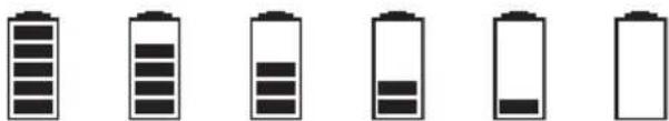
Battery (BC version only)
Indicates the battery charge status:
100% 70% 50% 30% 10% 0%
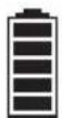
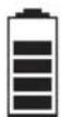
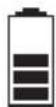
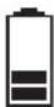

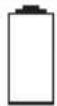
- With 10% battery, the brush function is disabled. The suction system remains in operation to be able to collect water residues on the floor.
- With 0% the machine is completely deactivated.

Brush
It shown on the display indicating the brush function.
Press the button (23) 📄 to deactivate (icon absent) or reactivate the brush function.

Detergent solution
Indicates the amount of detergent solution dispensed during the work cycle.
Press the button (25) to change the setting.

Vacuuming
It shown on the display when the button (26)
is pressed indicating the vacuum function in standard mode.

Silent mode vacuuming
It shown on the display when the button (26)
是|圆| is pressed, indicating the vacuum function in low-speed mode.

ECO mode
It shown on the display when the button (27)
ECO is pressed.

Brush release
It flashing shown on the display after pressing for 2 seconds the button (24)
8.1 - MACHINE HANDLING (Fig. A)
- With the help of the hands on the driving handle (1), slightly lift the front of machine body, then drive the machine up to the affected area.
9.1 - DETERGENT SOLUTION TANK
9.1.a - Tank filling (Fig. G)

WARNING:
Only add clean mains water to the tank at a temperature no greater than 50^ C.
- Open the left door (10).
- Remove the extractable hose (48) and connect it to a water outlet.
- Open the tap and fill the detergent solution tank (8).

WARNING:
The blue Led (49), when turned on, warns that the solution tank is full. Close the water tap.
- Add the liquid detergent in the concentration and in the method indicated on the label by the detergent manufacturer.

NOTE:
Use non-foamy detergents only. For the quantities, follow the instructions provided by the detergent manufacturer according to the type of dirt.

DANGER:
If the detergent comes in contact with the eyes and/or skin or if swallowed, refer to the use and safety information booklet provided by the manufacturer of the detergent.
- At the end of filling the tank, reposition the extractable tube (48) in its seat and close the left door (10).
10.1 - OPERATION
10.1.a - Checks before use (Fig. A)
Check that the cleaning solution tap (19) is correctly in the open position (19a).
- Check the state of charge of the batteries as indicated in the "Display" paragraph.
10.1.b - Preparing the machine and choosing the cycle (Fig. A)
- Press the button (23) to turn on the machine.
- Lower the squeegee unit (15) by acting on the pedal (3), releasing it from its coupling (3b).
- The machine has the possibility to perform 5 work cycles:
Washing, brushing, drying cycle:
- Press the button (26) to start the suction system.
- Press the button (25) to arrange the delivery of the cleaning solution, then press the levers (4) to start the cycle.
Washing, brushing, drying cycle, ECO SYSTEM mode:
- Press the button (27) to start the suction system and the delivery of the cleaning solution in low consumption mode, then press the levers (4) to start the cycle.
Drying only cycle:
- Repeatedly press the button (25) to deactivate the cleaning solution delivery system ("" icon on the display).
- Press the button (26) 🔑 to start the suction system, then press the levers (4) to start the cycle.
Washing, brushing cycle:
- Lift the squeegee assembly using the pedal (3) into position (3a).
- Press the button (26) until the suction system stops.
- Press the button (25) to arrange the delivery of the cleaning solution, then press the levers (4) to start the cycle.
Brushing only cycle:
- With the cleaning solution and the suction system deactivated, press the levers (4) to carry out the brushing cycle only; releasing the levers (4) the brush stops.
10.1.c - Using the machine (Fig. A)
- After starting the machine and choosing the type of cycle, start the cleaning operations by pressing the levers (4) and keeping them pressed to start the rotation of the brush and the dispensing of the detergent solution; then push the machine using the driving handle (1).

NOTE:
Releasing the levers (4) stops the rotation of the brush and the dispensing of water. To avoid damaging the floor, do not use the machine in a fixed position with brush rotation activated
The correct way of cleaning and drying the floor is to move the machine forwards. Moving the machine backwards damages the blades as well as not allowing correct aspiration of the water present on the floor.
- If necessary, adjust the amount of delivery of the cleaning solution using the button (25)
- (Only for BC version) Check the state of charge of the batteries as indicated in the "Display" paragraph.
10.1.d - End of use and switching off (Fig. A)
- At the end of the cleaning operations, before turning off the machine, stop the delivery of the detergent solution by pressing the button (25) 🔔 "icon on the display) and continue with the suction system activated to suck up all the liquid present in the floor.
- Lift the squeegee assembly using the pedal (3) into position (3a).
- Turn off the machine by pressing for 3 seconds the button (23)

WARNING:
Always lift up the squeegee at the end of cleaning in order to prevent the deformation of the rubber blades.
10.1.e - Parking the machine (Fig. A)
At the end of work, before leaving the machine:
- Make sure the squeegee unit (14) is raised.
- Remove the brush as indicated in the "Brush cleaning / replacement" paragraph.
- Empty the recovery water tank (6) as indicated in the specific paragraph.
- Perform the planned maintenance after using the machine (see chapter Maintenance and cleaning).
- Lift the machine in front by levering the handle (1) and move the machine to a dry and clean place prepared for storage.
- Make sure that the machine cannot move independently.
If you plan not to use the machine for more than 15 days, you should carry out the following operations:
- Close the detergent solution tap (19b).
- Disconnect the battery connector (67 Fig. M).

NOTE:
When parking the machine, it is recommended to place a spacer under the brush hub (38 Fig. C) to keep the brush deck raised
11.1 - DRAINING THE RECOVERY WATER (Fig. H)
At the end of the washing cycle or when the recovery water tank (6) is full, it is necessary to empty the tank by proceeding as follows:

NOTE:
To dispose of the recovery water, comply with the standards in force in the country in which the machine is used.
- Position yourself with the machine near an exhaust drain.
- Open the rear door (11).
- Detach the drain hose (50) from the support.
- Remove the cap (51) from the tube (50) and completely drain the water contained in the tank.
- Replace the cap (51) and reposition the drain hose (50) on the relative support.
- Close the rear door (11).
12.1 - MAINTENANCE AND CLEANING

WARNING:
For information and warnings related to maintenance and cleaning operations please follow what is indicated in the “Safety instructions for scrubber dryer machine” annexed to this one.
12.2 - OPERATIONS TO PERFORM DAILY
12.2.a - Emptying and cleaning the detergent solution tank (Fig. G)

WARNING:
At the end of the washing operations it is mandatory to drain and clean the detergent solution tank (8) to avoid deposits or encrustations.
After draining the recovery water tank (6), drain the cleaning detergent solution tank (8) as follows:
- Position yourself with the rear side of the machine on an exhaust drain.
- Open the cleaning solution drain tap (21b) and let the contained liquid completely drain.
- Wash the inside of the tank leaving the drain tap open and introducing clean water from the extractable tube (48) of the tank.
- At the end of the cleaning, close the drain tap (21a), reposition the extractable tube (48) in its seat and close the left door (10).
12.2.b - Cleaning the recovery water tank (Fig. H-I)

WARNING:
At the end of the washing operations, it is compulsory to clean the recovery water tank to prevent deposits or scaling and the proliferation of bacteria, odours or mould.
- Drain the recovery water as shown in the relative paragraph, positioning the machine over a drain outlet.
- Remove the cover (7) and clean the inside of the lid, the float (52) and the vacuum safety mesh filter (53) with running water.
- Leaving the hose (50) lowered and the cap off, add water through the upper opening (54), cleaning the inside of the tank until clean water comes out of the drain hose.
- Replace all the components in reverse order.
12.2.c - Squeegee cleaning (Fig. J)
To clean the squeegee (15) correctly, remove it as follows:
- Lower the squeegee assembly using the pedal (3 Fig A) to position (3b).
- Manually rotate the brush deck (13) to one side of the machine.
- Loosen the knobs (40) and remove the squeegee (15).
- Reverse and wash the squeegee and especially the rubber (55) and (56) and the inner frame of the suction fitting (27).

NOTE:
If, during washing, it is clear that the rubber blades (55) and (56) are damaged or worn, it is necessary to replace them or turn them over.
- Replace all the components in reverse order.
12.3 - OPERATIONS TO PERFORM WEEKLY
12.3.a - Cleaning the solution filter (Fig. G)
- Close the detergent solution tap (19b).
- Unscrew the transparent cover (58) of the filter and remove the filter (59).
- Clean the filter (59) with running water, replace it if it is clogged.
- Replace all the components in reverse order.
- Open the detergent solution tap (19a).
12.4 - OPERATIONS TO PERFORM WHEN NECESSARY
12.4.a - Brush cleaning / replacement (Fig. C)
It becomes necessary to replace the brush when it is worn with bristles shorter than 2 cm or it must be replaced according to the type of floor to wash; to replace it, proceed as follows:
- Make sure the squeegee unit (14) is raised.
- Press the button (23) to start the machine.
- Lift the machine from the front by leveraging the handle grips (1 Fig. A).
- With the brush holder head (13) raised, press for 2 seconds the brush release but-
ton (24) to activate the release function, then wait for the brush to fall to the floor.
- If this does not happen, repeat the operation.
- Clean and wash the brush with water and detergent or replace the brush.
- Place the brush deck (13) on top of the brush (14) so that the driving flange (38) is centered with the brush engagement hole.
- With the machine turned on and the presence of the "ON" on the display (22), press the levers (4) to start brush rotation until you hear the "CLICK" of the brush coupling, then release the levers (4).
- Press the button (23) for 3 sec. to turn off the machine.
12.4.b - Squeegee rubber blades cleaning / replacement (Fig. K)
When it becomes clear that drying the floor is difficult or traces of water remain on the floor, it is necessary to check the wear on the squeegee rubber blades:
- Remove the squeegee assembly (15) as indicated in the "squeegee cleaning" paragraph.
- Fully untighten the lug nuts (40) and knobs (60) completely, then remove the rubber squeegee group (61) from the closing frame (62).
- Remove the inner rubber (55) and the outer rubber (56) disengaging them from the squeegee grooves (63).
- Clean and wash the rubber blades with water and detergent.

NOTE:
When the rubber blades (55) or (56) are worn on one side, on one occasion they may be turned over.
- Replace or turn over the rubber blades (55) or (56) without inverting them.
- Replace all the components in reverse order.

NOTE:
Two types of rubber are available: Para rubber for all types of flooring and polyurethane rubber for workshop floors with oily residues.
12.4.c - Squeegee incidence set up (Fig. K)
- Lower the wiper assembly (15 Fig A) using the pedal into position (3b Fig. A).
- Start the suction system as indicated in the paragraph "Machine preparation and cycle choice" and proceed for a few metres, then switch off and stop the machine.
- Check the incidence of the tires on the floor.
A = too squashed
B = too raised
C = correct position.
- To adjust, loosen the nut (64) of the rear wheel (65) and move the wheel vertically along the slot; lifting the wheel increases the incidence, vice versa it decreases.
12.4.d - Lithium battery replacement (Fig. M)

WARNING:
The battery must be installed by qualified personnel only.
The electrical components of the machine can be seriously damaged if the battery is not installed and connected correctly.
Handle the battery with great care.
- Make sure the machine is switched off.
- Check that the recovery water tank is empty, otherwise discharge the liquid as indicated in the specific paragraph.
- Close the cleaning solution tap (19b).
- Open the rear door (11).
- Disconnect the suction pipe (66) from the recovery water tank (6).
- Detach the drain hose (50) from the support.
- Lift and remove the recovery water tank (6) to access the battery compartment.
- Unhook the cleanser pipe (68) to facilitate the removal of the battery.
- Untighten the two lug nuts (69) and the positive and negative battery terminals, and disconnect the (70) and (71) power cables.
- Using its handle, lift and replace the battery (72).
- Replace all the components in reverse order.

WARNING:
Be careful to reconnect the cleanser pipe (68) correctly.
13.1 - PARAMETER SETTING (Fig. A)
13.1.a - OPERATOR parameters
It is possible for the operator to have access to the menu to set the following parameters:
- Language
- Type of batteries
- Display - Contrast
• Display - Luminosity
To enter the menu act as follows:
- Press and hold the buttons (27) ; (25)
simultaneously and then the button
display the following screen
(22):


- Release the buttons pressed.
-
Enter the 4-digit Password "0010" by
pressing the button (23) to switch between the digits and the buttons (27)
or (25) to change the number of the flashing digit. -
Press the button (23) to confirm and go to the next digit, to finally confirm the password and have access to the parameters list.
- Press the button (27) or (25) to scroll through the parameters and then the button (23) to access the chosen parameter.
Language setting:

- Choose the language using the buttons
(27) or (25), then press the button
(23) to confirm the choice; - ITA = Italian
- ENG = English
Setting the type of battery:

This parameter is fixed and cannot be edited.
Display setting - Contrast:

Display tune Contrasto display
- Choose the type of contrast of the display by setting a value from "0 to 10" using the buttons (27) or (25), then press the button (23) to confirm the choice.
Display setting - Brightness:

Display brightnss Luminosità display
- Choose the type of brightness of the display by setting a value from "0 to 10" using the buttons (27) or (25), then press the button (23) to confirm the choice.
Exit - Operator parameters:
- Navigate to the main menu with the button (26) to the following screen:

- Press the button (23) to exit the operator parameter setting and restart the machine.
14.1 - FUSE CHECK/REPLACEMENT

NOTE:
All machine electrical circuits are protected by auto-resettable electronic devices. The safety fuse and relay activates only in case of serious damage. It is recommended to have the fuses replaced by qualified personnel only.
15.1 - ALARMS DURING THE FUNCTIONING
When a machine malfunction takes place, the display (22 Fig A) indicates the type of alarm according to the list shown below.
Consult the list and put in place the solution recommended to restore the correct functioning of the machine.
Should the recommended remedy fail to solve the problem, get in contact with the Technical Assistance Service.
| ALARM MEANING SOLUTION | ||
| AL_1 | Memory error Restart | the machine. |
| AL_2 | Key malfunction Turn off the machine for at least 10 seconds, then restart. | |
| AL_3 | Low voltage | Turn off the machine, check the status of the battery charge, fuses, contacts, cabling and connections, then restart the machine. |
| AL_4 | Excessive voltage | Turn off the machine, check the fuses, contacts, cabling and connections, then restart the machine. |
| AL_6 | Absence of communica-tion with the command dashboard or display | Turn off the machine, check the contacts, cabling and connec-tions, then restart the machine. |
| AL_41 | Overheating | Turn off and wait for the machine to cool down.Check the consumption of the brush and suction device mo-tors, the status of the ambient ventilation and restart. |
| AL_42 | Power damaged Turn off the machine for at least 10 seconds, then restart. | |
| AL_44 | Relay fault If persists replace the main board. | |
| AL_45 | Relay fault dc If persists replace the main board. | |
| AL_46 | Over-current Brushes | Turn off the machine, check the load (motor), the mechanics, the cabling and the connections, then look for the presence of a short circuit on the outlet, than restart.The 3 alarms can appear on the display simultaneously, but it signals an over-current on a single motor that cannot be determined with certainty. |
| AL_47 | Over-current Suction device | |
| AL_48 | Over-current Water pump | |
| AL_49 | Current measurement Brush | Check the consumption and the kind of application of the brush function, then restart the machine. |
| AL_52 | Current measurement Suction | Check the consumption and the suction device function, then restart the machine. |
16.1 - TROUBLESHOOTING
| PROBLEM CAUSE | SOLUTION | |
The machine does not start when pressing the  ut-ton. ut-ton. | Low battery (for BC version only). | Check that the battery is charged. |
| Plug disconnected (for E ver-sion only). | Connect the plug. | |
| The machine does not work correctly and the display (22) shows the error code: “AL_XX” | Alarm condition of the elec-tronic control system of the machine. | See paragraph “Alarms dur-ing functioning”. |
| The brush doesn’t turn. Levers | on the handle bar not pressed. | Press the levers. |
| Gearmotor fault. Replace gear motor. (*) | ||
| Faulty electronic board. Replace the electronic board. (*) | ||
| The suction unit does not function. | Recovery tank full. Empty the tank. | |
| Defective turbine motor. Replace the turbine motor. (*) | ||
| Faulty electronic board. Replace the electronic board. (*) | ||
| The machine does dry pro-erly, leaving traces of water on the floor. | Aspirator off. Start up the aspirator. | |
| Aspiration tube blocked. Check and if necessary clean the aspiration tube that connects the squeegee to the recovery tank. | ||
| Recovery tank full. Empty the recovery tank. | ||
| Squeegee rubber blades worn. | Replace or turn over the squeegee rubber blades. | |
| During the brush release op-eration, the brush does not release from the deck. | The squeegee assembly was not raised. | Lift the squeegee assembly and press the brush release button again. |
| The machine is too much tilted. | Do not lift the brush deck ex-cessively and press the brush release button again. | |
| PROBLEM CAUSE SOLUTION | ||
| No cleaning solution comes out. | Empty tank. Fill the tank. | |
| Closed tap valve. | Open the tap valve. | |
| Filter clogged. Clean the filter. | ||
| Pump solenoid valve not functioning. | Replace the solenoid valve pump. (*) | |
| Defective water pump. Replace the water pump. (*) | ||
| Faulty electronic board. Replace the electronic board. (*) | ||
| Insufficient floor cleaning. Unsuitable brushes or detergent. | Use brushes or detergents which are suitable for the type of floor or dirt to be cleaned. | |
(*) Call customer service to request replacement.
17.1 - DEMOLITION OF THE MACHINE

DANGER:
Lithium battery and electrical parts are to be considered as special waste and must therefore be disposed of at appropriate collection facilities, as prescribed by the current regulations in the country of use.
18.1 - WIRING DIAGRAM
Key:
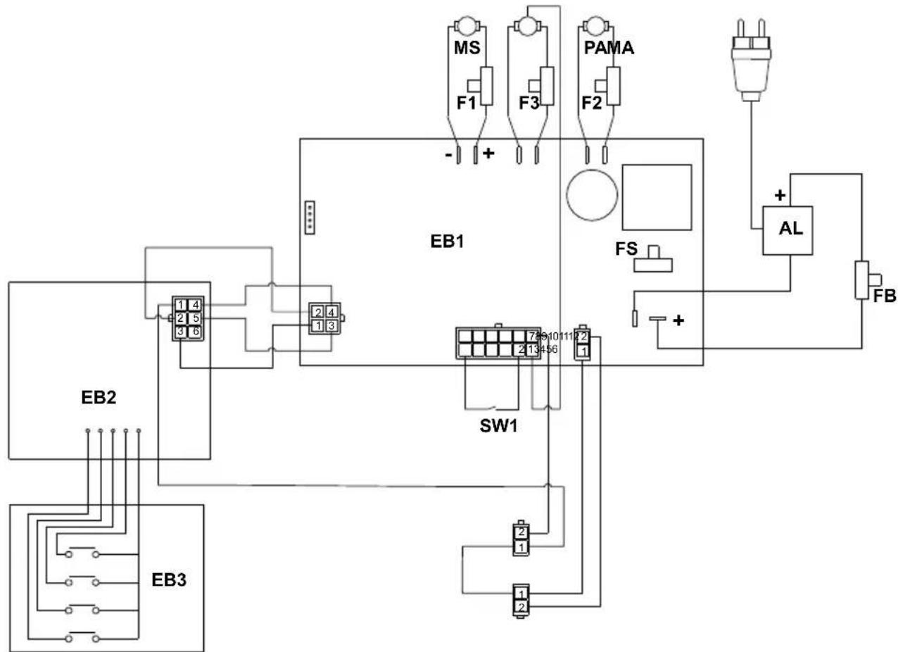
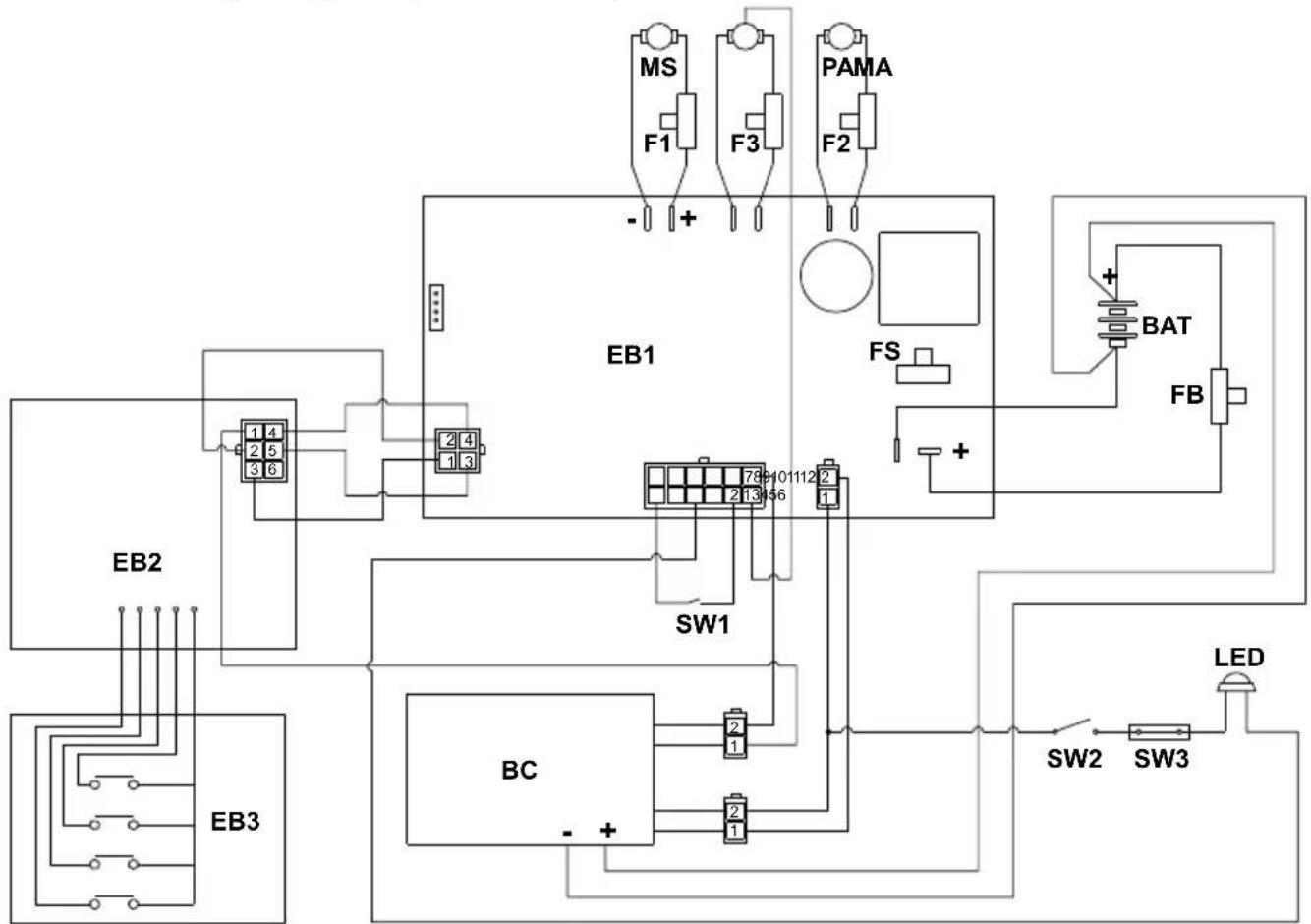
| AL Power supply (E) | |
| BAT | Battery (BC) |
| BC | Battery charger (BC) |
| EB1 | Electronic functions card |
| EB2 | Display |
| EB3 | Control panel |
| F1 | Brush fuse (3A) |
| F2 | Water pump fuse (10A) |
| F3 | Vacuum fuse (10A) |
| FB Battery fuse (40A) | |
| FS | Functions card fuse (10A) |
| MA | Vacuum motor |
| MS | Brush motor |
| PA | Water pump |
| SW1 | Lever microswitch |
| SW2 | Float switch |
| SW3 | Magnetic door switch |
| LED | Filling warning LED |
Colour codes:
| BK | Black |
| BU | Blue |
| BN | Brown |
| GN | Green |
| GY | Grey |
| OG | Orange |
| PK | Pink |
| RD | Red |
| VT | Violet |
| WT | White |
| YE Yellow | |
18.1.a - Wiring diagram (E version)
flowchart
graph TD
    EB2["EB2"] --> 1["1 4"]
    EB2 --> 2["2 5"]
    EB2 --> 3["3 6"]
    EB3["EB3"] --> 1
    EB3 --> 2
    EB3 --> 3
    EB1["EB1"] --> 789101112.2["789101112.2"]
    SW1["SW1"] --> 789101112.2
    SW1 --> 2
    SW1 --> 1
    SW1 --> 2
    MS["MS"] --> F1["F1"]
    F1 --> -1
    F3["P3"] --> F2["F2"]
    F2 --> +1
    PAMA["PAMA"] --> FS["FS"]
    FS --> +1
    AL["AL"] --> FB["FB"]
    FB --> +1
    -1 --> +1
    +1 --> -1
18.1.b - Wiring diagram (BC version)
flowchart
graph TD
    EB1["EB1"] -->|+| F1["F1"]
    EB1 -->|+| F3["F3"]
    EB1 -->|+| PAMA["PAMA"]
    EB1 -->|+| FS["FS"]
    EB1 -->|+| BAT["BAT"]
    EB1 -->|+| FB["FB"]
    EB2["EB2"] --> 1["1 4"]
    EB2 --> 2["2 5"]
    EB2 --> 3["3 6"]
    EB2 --> 4["2 4"]
    EB2 --> 5["1 3"]
    EB2 --> SW1["SW1"]
    EB2 --> SW2["SW2"]
    EB2 --> SW3["SW3"]
    EB3["EB3"] --> 1
    EB3 --> 2
    EB3 --> 3
    EB3 --> 4
    EB3 --> 5
    EB3 --> 6
    EB3 --> 7
    EB3 --> 8
    EB3 --> 9
    EB3 --> 10
    EB3 --> 11
    EB3 --> 12
    EB3 --> 13
    EB3 --> 14
    EB3 --> 15
    EB3 --> 16
    EB3 --> 17
    EB3 --> 18
    EB3 --> 19
    EB3 --> 20
    EB3 --> 21
    EB3 --> 22
    EB3 --> 23
    EB3 --> 24
    EB3 --> 25
    EB3 --> 26
    EB3 --> 27
    EB3 --> 28
    EB3 --> 29
    EB3 --> 30
    EB3 --> 31
    EB3 --> 32
    EB3 --> 33
    EB3 --> 34
    EB3 --> 35
    EB3 --> 36
    EB3 --> 37
    EB3 --> 38
    EB3 --> 39
    EB3 --> 40
    EB3 --> 41
    EB3 --> 42
    EB3 --> 43
    EB3 --> 44
    EB3 --> 45
    EB3 --> 46
    EB3 --> 47
    EB3 --> 48
    EB3 --> 49
    EB3 --> 50
    EB3 --> 51
    EB3 --> 52
    EB3 --> 53
    EB3 --> 54
    EB3 --> 55
    EB3 --> 56
    EB3 --> 57
    EB3 --> 58
    EB3 --> 59
    EB3 --> 60
    EB3 --> 61
    EB3 --> 62
    EB3 --> 63
    EB3 --> 64
    EB3 --> 65
    EB3 --> 66
    EB3 --> 67
    EB3 --> 68
    EB3 --> 69
    EB3 --> 70
    EB3 --> 71
    EB3 --> 72
    EB3 --> 73
    EB3 --> 74
    EB3 --> 75
    EB3 --> 76
    EB3 --> 77
    EB3 --> 78
    EB3 --> 79
    EB3 --> 80
    EB3 --> 81
    EB3 --> 82
    EB3 --> 83
    EB3 --> 84
    EB3 --> 85
    EB3 --> 86
    EB3 --> 87
    EB3 --> 88
    EB3 --> 89
    EB3 --> 90
    EB3 --> 91
    EB3 --> 92
    EB3 --> 93
    EB3 --> 94
    EB3 --> 95
    EB3 --> 96
    EB3 --> 97
    EB3 --> 98
    EB3 --> 99
    EB3 --> SW1["SW1"]
    EB3 --> SW2["SW2"]
    EB3 --> SW3["SW3"]
    EB3 --> SW4["SW4"]
    EB3 --> SW5["SW5"]
    EB3 --> SW6["SW6"]
    EB3 --> SW7["SW7"]
    EB3 --> SW8["SW8"]
    EB3 --> SW9["SW9"]
    EB3 --> SW10["SW10"]
    EB3 --> SW11["SW11"]
    EB3 --> SW12["SW12"]
    EB3 --> SW13["SW13"]
    EB3 --> SW14["SW14"]
    EB3 --> SW15["SW15"]
    EB3 --> SW16["SW16"]
    EB3 --> SW17["SW17"]
    EB3 --> SW18["SW18"]
    EB3 --> SW19["SW19"]
    EB3 --> SW20["SW20"]
    EB3 --> SW21["SW21"]
    EB3 --> SW22["SW22"]
    EB3 --> SW23["SW23"]
    EB3 --> SW24["SW24"]
    EB3 --> SW25["SW25"]
    EB3 --> SW26["SW26"]
    EB3 --> SW27["SW27"]
    EB3 --> SW28["SW28"]
    EB3 --> SW29["SW29"]
    EB3 --> SW30["SW30"]
    EB3 --> SW20
Cher client,
DONNÉES DES MATIÈRES....3
1.1 - INTRODUCTION......4
2.1 - CONNAISSANCE DE LA MACHINE (Fig. A) 4
3.1 - DÉSEMBALLAGE 4
100% 70% 50% 30% 10% 0%


Language selection: Language selection
Battery type: Battery type selection

REMARQUE :
Battery type: Batterietyp

HINWEIS:
16.1 - BÚSQUEDA AVERÍAS 17
100% 70% 50% 30% 10% 0%


16.1 - BÚSQUEDA AVERÍAS
100% 70% 50% 30% 10% 0%


Language selection: Language selection
- Reinigingsoplossing = minimale dose-ring.
• Zuiging = stille modus
100% 70% 50% 30% 10% 0%


- Add the liquid detergent in the concentration and in the method indicated on the label by the detergent manufacturer.

OPMERKING:
Language selection: Language selection
100% 70% 50% 30% 10% 0%
natural_image
Seven battery icons in black and white, arranged horizontally (no text or symbols)At the end of the washing operations it is mandatory to drain and clean the detergent solution tank (8) to avoid deposits or encrustations.
Language selection: Volba jazyka
Battery type: Volba typu baterie

POZNÁMKA:
Language selection: Выбор языка
At the end of work, before leaving the machine:
اللغة Santiago Language selection
الختيار نوعprobability Battery Type
ملاحظة:

0% 10% 30% 50% 70% 100%


Professional Cleaning Machines Since 1968
DEALER
Cod. 49.0321.00 - 7 ^n ed. - 06/2024
GHIBLI & WIRBEL S.p.A.
Registered office:
Via Enrico Fermi, 43 - 37136 Verona (VR) - Italy
Headquarters: