ROUND 45 M 55 TOUCH - Scrubber Ghibli & Wirbel - Free user manual and instructions
Find the device manual for free ROUND 45 M 55 TOUCH Ghibli & Wirbel in PDF.

| Product type | Walk-behind scrubber dryer |
| Brand | Ghibli & Wirbel |
| Model | ROUND 45 M 55 TOUCH |
| Power supply | Battery (voltage according to rating plate) |
| Installed power | 1060 W |
| Cleaning width | 530 mm |
| Suction width | 750 mm |
| Theoretical performance | 2120 m²/h |
| Solution tank capacity | 45 L |
| Recovery tank capacity | 47 L |
| Battery type | Gel (adjustable AGM or Acid) |
| Brush motor | 500 W, 165 rpm |
| Suction motor | 550 W, depression 1791 mmH₂O, flow 30 L/s |
| Noise level | 57–63 dB(A) |
| Vibrations | < 2.5 m/s² (ISO 5349) |
| Dimensions (L × W × H) | 1210 × 560 × 1040 mm (without squeegee) |
| Empty weight | 90.5 kg |
| Weight with batteries | 143.5 kg |
| Operating weight | 188.5 kg |
| Drive mode | Manual (without traction) |
| Cleaning functions | Washing, brushing, drying, combination, ECO mode |
| Included accessories | PPL 0.7 brush, squeegee, water hose, manual |
Frequently Asked Questions - ROUND 45 M 55 TOUCH Ghibli & Wirbel
User questions about ROUND 45 M 55 TOUCH Ghibli & Wirbel
0 question about this device. Answer the ones you know or ask your own.
Ask a new question about this device
Download the instructions for your Scrubber in PDF format for free! Find your manual ROUND 45 M 55 TOUCH - Ghibli & Wirbel and take your electronic device back in hand. On this page are published all the documents necessary for the use of your device. ROUND 45 M 55 TOUCH by Ghibli & Wirbel.
USER MANUAL ROUND 45 M 55 TOUCH Ghibli & Wirbel
natural_image
Line drawing of a cleaning or cleaning service robot (no text or symbols visible)ROUND45
TOUCH

CE
49.0260.00
ed. 04/2023
EN Use and Maintenance
EN English ENGLISH -1
(Translation of original instructions)
FR Français ...... FRANÇAIS -1
Thank you for choosing one of our cleaning products.
The floor scrubber dryer that you have purchased has been designed to satisfy the user in terms of ease of use and reliability over time.
We are aware that in order for a good product to stay that way, over time, it requires continuous updates aimed at meeting the expectations of those who use it on a daily basis. For this reason, we hope that you will not only be a satisfied customer but also a partner who does not hesitate to give us your opinions and ideas originating from your personal day-to-day experience.
Contents
Technical data......EN-3
1.1 Introduction......EN-5
2.1 Getting to know the machine......EN-5
3.1 Unpacking......EN-5
3.1.a Standard machine equipment ......EN-5
4.1 Assembling the components......EN-5
4.1.a Wiper assembly......EN-5
4.1.b Brush assembly......EN-5
4.1.c Installing and connecting the batteries......EN-6
5.1 Charging the battery......EN-6
5.1.a Charging the battery using the on board battery charger (if present)....EN-6
5.1.b Charging the battery using an external battery charger......EN-7
6.1 Control panel......EN-7
6.2 Working cycle example ......EN-9
7.0 Safety password ......EN-9
7.1 Parameter setting......EN-9
7.1.a Language setting......EN-10
7.1.b Battery type setting.....EN-10
7.1.c Brightness and contrast setting......EN-10
7.1.d Enable the chemical agent (optional)......EN-11
8.1 Display....EN-11
9.1 Filling the tank ......EN-12
9.2 Filling the chemical agent tank (optional) ......EN-12
10.1 Operation......EN-12
10.1.a Checks before use......EN-11
10.1.b Preparing the machine and choosing the cycle ......EN-12
10.1.c Using the machine ......EN-13
10.1.d Adjusting the movement direction......EN-14
10.1.e Adjusting traction help (only for models without traction)......EN-14
10.1.f End of use and switching off ......EN-14
10.1.g Maximum recovery tank water level alarm ......EN-14
10.1.h Alarms list ......EN-15
11.1 Draining the recovery water......EN-16
12.1 Maintenance and cleaning......EN-16
12.1.a Removable splash guard....EN-16
12.1.b Emptying and cleaning the clean water tank ......EN-16
12.1.c Cleaning the recovery water tank......EN-17
12.1.d Cleaning the squeegee......EN-17
12.1.e Cleaning the clean water filter......EN-17
12.1.f Replacing the brush....EN-17
12.1.g Replacing the squeegee rubber blades....EN-18
12.1.h Cleaning the recovery water tank......EN-18
12.1.i Cleaning the suction filter......EN-18
12.1.I Replacing the fuses.....EN-18
12.1.m Wiper adjustment......EN-19
12.1.n Battery charger and digital instrument configuration......EN-19
Troubleshooting......EN-20
13.1 Warranty ......EN-21
Wiring diagram ......EN-22
Technical data
| 45M55 45D5 | 5 45D60 | ||
| Type of use Operator on ground | |||
| Characteristics | |||
| Power supply Battery Battery Battery | |||
| Power supply voltage See technical data plate | |||
| Installed load 1060 W 1240 W 1190 W | |||
| Forward movement Manual Tractioned Tractioned | |||
| Washing width * 530 mm 530 mm 600 mm | |||
| Drying width 750 mm 750 mm 750 mm | |||
| Theoretical hourly working capacity 2120 m ^2 /h | 2650 m ^2 /h | 3050 m ^2 /h | |
| Brushes / Pad | |||
| Diameter / Number | 530mm/21" | 530mm/21" 310mm/12"x2 | |
| Motor power / number | 500 Wx1 | 500 Wx1 | 450 Wx1 |
| Motor speed | 165 rpm | 165 rpm. | 200 rpm |
| Specific pressure | 16,5 ÷ 19,7 gr/cm ^2 | 16,5 ÷ 19,7 gr/cm ^2 | 18,8 ÷ 22,0 gr/cm ^2 |
| Carter weight | 25,5 ÷ 30,5 Kg | 25,5 ÷ 30,5 Kg | 27 ÷ 32 Kg |
| Aspiration | |||
| Motor power | 550 W | 550 W | 550 W |
| Negative pressure | 1791 mmH _2 O | 1791 mmH _2 O | 1791 mmH _2 O |
| Air flow rate 30 l / sec 30 l / sec 30 l / sec | |||
| Noise level | Min. 57 dB (A) ☑ / Max. 63 dB (A) ☑ | ||
| Traction | |||
| Engine power | --- | 180 W | 180 W |
| Tank | |||
| Recirculation | No | No | No |
| Solution capacity | 45 l | 45 l | 45 l |
| Recovery capacity 47 l | 47 l | 47 l | |
| Dimensions (lxwxh) without wiper | 1210 x 560 x 1040 mm | 1210 x 560 x 1020 mm | 1125 x 670 x 1040 mm |
| Vibrations ISO 5349 m/sec ^2 | < 2,5 | < 2,5 | < 2,5 |
| Weight | |||
| Empty weight | 90,5 Kg | 109 Kg 116 Kg | |
| Weight with batteries | 143,5 Kg 189 | Kg 196 Kg | |
| Weight in running order GVW | 188,5 Kg 234 | Kg 241 Kg | |
* The washing width is intended with the machine operating and the brush pressed down.
| 45M55 45D55 45D60 | |||
| Accessories | |||
| 0.7 ø PPL brush 40.0003.00 | POLY 0,7 | 40.0003.00 POLY 0,7 | 2x40.0001.00 POLY 0,7 |
| Brush spray guard 24.0265.00 + | 40.4003.00 | 24.0265.00 + 40.4003.00 | 24.0266.00 + 40.4007.00 |
| Front rubber wiper element 39.0110.00 | 39.0110.00 39.0110.00 | ||
| Rear rubber wiper element 39.0111.00 | 39.0111.00 39.0111.00 | ||
| Water loading tube 30.0024.00 30.00 | 24.00 30.0024.00 | ||
| Optional accessories | |||
| 0.9 ø PPL strong brush 40.0103.00 | POLY 0,9 | 40.0103.00 POLY 0,9 | 40.0101.00 POLY 0,9 |
| 1.2 ø PPL brush 40.0303.00 40.0303.00 | 40.0301.00 | ||
| 1.2 ø tynex brush 40.0203.00 40.0203.00 | 40.0201.00 | ||
| Set polyurethane rubbers 95.0055.00 | 95.0055.00 95.0055.00 | ||
| Drive mechanism 40.1003.00 40.1003.00 | 2x40.1001.00 | ||
1.1 INTRODUCTION

DANGER:
Before using the machine, carefully read the attached "SAFETY WARNINGS FOR THE FLOOR SCRUBBER DRYER" manual.
2.1 GETTING TO KNOW THE MACHINE (Fig. 1)
1) Guide handle.
2) Control console.
3) Squeegee activation lever.
4) Water supply tap.
5) Solution tank.
6) Tank cover.
7) Clean water filling opening.
8) Wheels.
9) Removable splash guard.
10) Brush.
11) Squeegee.
12) Recovery water drain hose.
13) Squeegee water aspiration hose.
14) Recovery water tank.
15) Clean water drain/level tube.
16) Water filter.
17) Clean water filter.
20) Touch sensor for the start-up and rotation of the brush/es.
3.1 UNPACKING (Figg. 1-2)
Once the packaging has been removed as shown in the instructions on the packaging itself, check that the machine and all the components supplied are intact.
If any evident damage is found, contact the area agent and the carrier within 3 days of receipt.
- Remove the bag (21) containing the accessories.
- Cut the strap (22).
- Remove the wooden blocks (23 and 24).
- Lift the brush flange (9) by pressing down on the pedal (19) (see relative paragraph).
- Lift the wiper support (25) by lifting the
handle (3 Fig. 1) (see relative paragraph).
- Position a chute and unload the machine from the bench.
3.1.a - Standard machine equipment (Fig. 3)
The accessories supplied are as follows:
10) Brush/brushes.
11) Wiper.
26) Water filling hose.
27) Machine use and maintenance manual.
28) Battery charger instruction manual (if present).
29) Battery charger power cable (if present).
30) 5A fuse.
31) Filter for clean water tank opening.
4.1 ASSEMBLING THE COMPONENTS
4.1.a - Wiper assembly (Fig. 4)
- Loosen the two handwheels (32) located on the wiper (11).
- Assemble the wiper (11) on the support (25), tightening the two handwheels (32).
- Connect the tube (13) to the wiper connector (33).

N.B.:
Perform the previous operations with the wiper support lowered.
4.1.b - Brush assembly (Fig. 5)

HAZARD:
Operation to be performed by two people!
- Raise the splash guard (9) and remove the polystyrene protection (34).
- Assemble the brush as described in the paragraph "replacing the brush".
4.1.c - Installing and connecting the batteries (Fig. 6)

WARNING:
CHECK THAT THE RECOVERY TANK AND THE CLEAN WATER TANK ARE EMPTY.
- Disconnect the plug (35).
- Press the button (36) and lift the tank (14) until completely overturned.
- Position the batteries (37) as shown in the figure and connect them as shown on the chart in Fig. 6 using the cables supplied.
- Tighten the terminals (38) using an insulated wrench.
- Lower the tank (14) until a coupling "click" is heard.
- Connect the plug (35) to the relevant socket (39).

N.B.:
The battery must be connected by specialised personnel.
5.1 CHARGING THE BATTERY

DANGER:
Charge the batteries in rooms which are well-ventilated and comply with applicable regulations in the country of use.
For safety-related information, follow what is described in chapter 1 of this manual.

WARNING:
For information and warnings about the battery and on board battery charger (if present) follow what is described in the battery charger manual enclosed with this document.

WARNING:
When the machine leaves the factory, it is calibrated to operate with gel batteries.
If other types of batteries are installed, see the paragraph "Parameter setting". The use of gel batteries with calibration for acid or other batteries is prohibited.

NOTE:
10 hours are needed for complete battery charging. Avoid partial recharges.
5.1.a - Charging the battery using the on board battery charger (if present) (Fig. 7)
- Move the machine close to a mains electricity socket.

WARNING:
It is important to first connect the cable (41) to the socket (42) and then connect the cable (41) to the power socket.
- Take the cable (41) from its seat and connect it to the socket (42) on the machine, then connect the other end to the mains power socket.
- Check that the green LED (43) flashes 2 times and then goes from the color "Green" to continuously lit "Red".

WARNING:
Make sure that the mains electrical voltage is compatible with the battery charger's operating voltage (230 Vac for the European market; 115 Vac for the American market; 50/60 Hz).
- Leave the batteries to charge until the "Green" LED (43) lights up, then remove the power cable (41) and put it away.
- Reconnect the battery plug (35) to the system socket (39).
5.1.b - Charging the battery using an external battery charger (Fig. 8)

WARNING:
It is important to first connect the plug (35) to the socket (44) of the battery charger and then connect the battery charger to the mains socket, otherwise the batteries will not charge.
- Move the machine close to the battery charging station.
- Remove the battery plug (35) from the system socket (39).
- Connect the battery plug (35) to the external battery charger socket (44).
6.1 CONTROL PANEL
(Fig. 9)

WARNING:
Before using the machine you must select the washing cycle as shown in the relevant paragraph.
20) Touch sensor for the start-up and rotation of the brush/es
• (for model with traction)
Check the display so that the minimum traction speed is set.
Acting on the touch sensor (20) with but-
ton(45) " "button (52) " and but-
ton (51) “” inserted, it starts the traction and rotation of the brush/es and the water supply.
The machine will automatically start moving forward.
To move in reverse, lift the wiper.
20) Sensor for the start of the rotation of the brush/es
• (for model with traction)
Acting on the touch sensor (20) with button (45) “💡” button (52) “💡” and button (51) “💡” inserted it starts the rotation of the brush and the water supply.
45) Main switch “ ⏻ ”
By pressing the button, voltage is inserted in the circuits allowing the operation of commands and of the appropriate buttons; the display (46) will turn on.
Press the button again to disconnect the voltage from the circuits.
46) Display
It lights up after the voltage is supplied to the circuits using the button (45) "
The display indicates the machine status, battery charge, working hours (for model with traction) and alarm messages.
47) Speed control buttons
(for model with traction only)
Button (47a) “”.

Pressed, increases the traction speed.
Button (47b) “ ”.

Pressed, decreases the traction speed.
The display (46) indicates the set speed.
48) Reverse button “” (for model with traction only)
Check the display so that the minimum traction speed is set.
Pressed and held, while action on the touch sensor (20), the machine will move in reverse to the operator. The display will show the following symbol "R". To move in reverse, lift the wiper.
50) Button with double function - Aspirator start and Quiet operation

Starting the aspirator
Pressing the switch (50) “it starts the aspiration to silent. Pressing the switch (50) “you switch from silent to standard mode, the display shows the symbol “朵”.

WARNING:
The suction motor will start only by touching the touch sensor. To turn off the suction press the button (50). The turbine will continue to operate for a few seconds so as to aspirate the liquid present on the floor, after which it will automatically turn off. The display will disappear the symbol “
Quiet operation

It lights up the icon " " silent mode, for starting the engine, you have to touch the touch sensor (20).
51) Water solenoid valve button

Button operation is enabled by pressing the button (45) “💡” and button (52) “💡”.
By pressing the button (51) "", on the
display will be shown the symbol “”, and the opening of the water valve is being prepared. The operation thereof is controlled by the touch sensor (20). By repeatedly pressing the button (51) “
⑤ "the amount of water is increased; once the maximum amount is reached, the display will show the symbol " pressing the button (51) again will deactivate the function.
52) Brush rotation enable button "
Button operation is enabled by pressing the button (45) "
Pressing the button (52) “”, will enable the rotation of the brush/es; the display will show the symbol “.” The operation of the brush/es is controlled by the touch sensor (20).
To stop brush rotation, press the button
(52) “
49) Chemical agent dosing button (optional)
By pressing the button (49) "☐" the display will show the symbol "☐" activating the operation of the chemical agent dosing pump.
By repeatedly pressing the button (49) " [icon] " the amount of dosed chemical agent is increased; once the maximum amount is reached, the display will show the symbol " [icon]"; pressing the button (49) again will disable the function.
Pressing the “ECO” the parameters of water, chemical and suction mode assume the following values.
- Water the second mark..
- Chemical 0,2%.
- Aspiratin silent mode.
Pressing the button "ECO" again, these parameters return to their initial settings.
6.2 WORKING CYCLE EXAMPLE (Fig. 9)
Setting a washing cycle with brushes and drying.
- Press the button (51) to allow the water supply.
- Press the button (52) to allow brush rotation.
- Press the button (50) and the vacuum will start.

NOTE:
In particular settings you can activate the silencer function by acting as indicated above.

WARNING:
When turned on, be careful not to touch the touch sensor (20); the machine triggers an alarm and the “” symbol flashes on the display.
If you release the touch sensor (20) within two seconds, the alarm is automatically switched off, after other two seconds you must restart the machine.
- Select the desired speed by pressing the buttons (47a) or (47b) (only for the model equipped with traction).

NOTE:
It is possible to change the speed even during the working cycle, with the machine in motion by acting the appropriate buttons.
- Touch the touch button (20), the machine starts the set program and starts the working cycle.

NOTE:
It is possible to change the working cycle depending on the work requirements.
By varying the working cycle, you must stop the machine, set a new cycle and start the cycle, by touching the touch button(20).
7.0 SAFETY PASSWORD
The machine can be equipped with a safety passwords; for enabling it or disabling it, please contact technical support. If the password was enabled, in order to enter the numbers follow the instructions on the display.
The password will remain active for 75 minutes after having it switched off or after the last use; if you want to re-enable the introduction of the password proceed as follows:
Turn off the machine, unplug the battery connector (35 Fig. 7) for a few seconds and then reconnect it.
When the machine is turned on again it will require a password.
7.1 PARAMETER SETTING (Fig. 9)
The operator can access the menu to set the following parameters:
Language;
Battery type;
Brightness / Contrast;
Chemical agent dispenser.
Proceed as follows to access the menu:
- Press and hold down (48) " and (52)
“” then press the power button (45) “” to start the machine until you see the following display:

- Release the pressed keys.
- Enter the passwords by pressing the keys (47a) (47b) until the display shows the number "10".
- Press the button (51) " " to confirm the password and enter the parameter setting menu; the following screen appears:

- To browse the parameter setting menu, press the button (52) "and the following screens will appear in succession:


7.1.a - Language setting
- Enter the parameter setting menu until the following screen appears:

- Select the language (47a) and (47b), then press the buttons (51) "to confirm your selection.
7.1.b - Battery type setting
- Enter the parameter setting menu until the following screen appears:

- Select the battery type by using the buttons (47a) and (47b), then press the but-
ton (51) "to confirm your selection;
$$ \mathbf {G E L} = \text { Gel battery } $$
$$ \mathbf {A G M} = \mathbf {A G M} \text { battery } $$
$$ \mathbf {W E T} = \text { ACID battery } $$
7.1.c - Brightness and contrast setting
- Enter the parameter setting menu until the following screen appears:

- Set the display brightness by selecting a value from "0 to 10" with the buttons (47a) and (47b), then press the button (52) "
“” to go to the contrast settings.

- Set the display contrast by selecting a value from "5 to 50" with the buttons (47a) and (47b), then press the button (51) "to confirm your selection.
7.1.d - Enable the chemical agent (optional)
- Enter the parameter setting menu until the following screen appears:

- Enable or disable the pump by using the buttons (47a) and (47b) and selecting
Disable to disable it or "Enabled" to enable it and then press the button (51) "

' to confirm your choice.
8.1 DISPLAY (Fig. 9-10)
The following pictograms appear on the display:
“A” ^+ =Battery
Indicates the battery charge status;
“A1” + - = battery charged;
"A2" + - = battery discharged.

= traction speed (if present)
The movement speed can be changed from "0" to the maximum speed in 5 steps, using
buttons “” and “” to increase or decrease the speed.
“”B reverse (if present)
This appears on the display when selecting the button “” and a reverse operation is performed; when the button is released the pictogram disappears.
"Aspirator operating
This appears on the display when selecting the button “” indicating that the aspirator is operating; when repressing the button “” to stop operation, the pictogram will flash for a few seconds and disappears when the aspirator stops.
“”Silent operation
Vacuum in operation.
This appears on the display when selecting the button “” indicating that the aspirator is operating at a reduced speed; by pressing again the button “” and holding it for a few seconds, the symbol “” will disappear and then you will see the symbol “朵” activating the normal operation.
“”= Water dispensing presetting
This appears on the display when select-
ing the button “indicating that the water dispensing solenoid valve is enabled; by repeatedly pressing the button (51) “the amount of water is increased; once the maximum amount is reached, the display will show the symbol ”repressing the button (51) will disable the function.
“Brush rotation presetting
This appears on the display when selecting the button “indicating that brush rotation is enabled; when repressing the button “” brush rotation motor operation is disabled and the pictogram disappears.
“Maximum fluid level in the tank
This displays when the fluid in the recovery tank has reached hte maximum level.
“” = Chemical agent dispenser (optional)
This appears on the screen when you press the button (49) "☐" indicating the dispensed amount of chemical agent.
“ECO” = ECO mode
It displays, when the ECO function is active, with the button (88) (88) “ECO”.
9.1 FILLING THE TANK (Fig. 11)

WARNING:
Only add clean mains water to the tank at a temperature no greater than 50°C.
- Before filling the tank, check the level of the chemical agent (if any), as indicated in the relevant section.
- Remove the hose (26) supplied, connect one end (26a) to a tap and insert the other end (26b) in the tank (5).
-
Check that the tap (53) is open.
-
Turn on the tap and fill the tank (5).
- Turn on the tap and fill the tank (5) to the MAXIMUM LEVEL (NOT EXCEED) indicated by the label placed on the transparent tube (15).
- Pour the detergent fluid in the tank.

NOTE:
Use non-foamy detergents only. For the quantities, follow the instructions provided by the detergent manufacturer according to the type of dirt.

DANGER:
If the detergent comes in contact with the eyes and/or skin or if swallowed, refer to the use and safety information booklet provided by the manufacturer of the detergent.
9.2 FILLING THE CHEMICAL AGENT TANK (optional) (Fig. 6-12)

WARNING:
MAKE SURE THAT THE RECOVERY TANK IS EMPTY.
- Press the button (36 Fig. 6) and lift the tank (14 Fig. 6) until complete overturning.
- Release the lock (74 Fig. 12) and remove the cap (75 Fig. 12) of the tank (76 Fig. 12).
- Place the suction tube (77 Fig. 12) and close the tank with the cap.
- Lower the tank (14 Fig. 6) until you hear a coupling "Click".

DANGER:
In case the chemical agent gets in contact with eyes and skin or in case of ingestion please refer to the Safety data sheet and the instructions of use of the chemical agent manufacturer.
10.1 OPERATION (Fig. 1-9)
10.1.a - Checks before use
- Check that the exhaust tube (12) of the recovery tank is properly coupled and properly sealed.
- Check that the connector (54) on the squeegee (11) is not blocked and that the hose is connected correctly.
- Check that the clean water exhaust tube (15) is correctly coupled to the supports and that the tap (53) is open.
- Press the button (45) and check the battery charge state on the display.
- Check if in the chemical agent tank (optional) is enough product for the daily needs.
10.1.b - Preparing the machine and choosing the cycle (Fig. 9-13)
- Press the button (45 Fig.9), the display (46 Fig.9) lights up, indicating the battery charge status.
- Release the lever (3 Fig. 13) and lower it; the floor squeegee (11 Fig. 13) is lowered.
- Press the pedal (19 Fig. 13), disengage it from its lodging and lift it: the brush/brushes (10 Fig. 1) will be lowered.

NOTE:
The brush has two working positions;
Normal position "A"
It is automatically placed when you release the pedal (19 Fig. 13) from the lifted position.
Position for persistent dirt "B"
From the “A” working position, lift the pedal (19 Fig. 13) and engage it in the “B1” holder; an additional pressure of 5 kg will be exercised on the brush.
Working cycle:
- The machine can perform 4 working cycles:
Drying only cycle:
- To perform only the drying cycle, press the button (50 Fig. 9), the aspirator will start.
Use the appropriate controls to activate the drive mechanism, if available for the model in use.
Brushing only cycle:
- To perform only the brushing cycle, press the button (52 Fig. 9) to enable brush rotation.
Touch the touch sensor to start the rotation of the brush/es (for models with integrated traction it also starts traction).
Washing, brushing cycle:
- Press the button (52 Fig. 9) to enable brush rotation, press the button (51 Fig. 9) to enable water dispensing.
Touch the touch sensor to start the rotation of the brush/es and the water supply (for models with integrated traction it also starts traction).
Washing, brushing, drying cycle:
- Press the button (50 Fig. 9) to start the aspirator, button (52 Fig. 9) to enable brush rotation and press the button (51 Fig. 9) to enable water dispensing.
Touch the touch sensor to start the rotation of the brush/es and the water supply (for models with integrated traction it also starts traction).
10.1.c - Using the machine (Fig. 1)
- After starting the machine and choosing the type of cycle, start cleaning, by pushing the machine using the handle (1 Fig. 1) or by touching the touch sensor (20 Fig. 1), to start the drive (for models with).

NOTE:
Pay attention to particularly delicate floors; do not use the machine while it's stopped and the brush rotation on.
For particularly dirty spots, adjust the traction speed to "0" so the brush will rotate in the same position, without straining the traction motor.

NOTE:
The proper cleaning and drying of the floor is done by pushing the machine forwards; if you go backwards the machine will not perform drying; in this phase, always lift the wiper to avoid damaging the blades.
- Adjust the traction speed (if present) as shown above.
- If necessary, adjust the amount of washing water through the button (51 Fig. 9).
- If necessary, adjust the amount of chemical agent (optional) with the help of the button (49 Fig. 9).
- Check the battery charge status on the display.

NOTE:
After 3 minutes of inactivity the machine shuts off automatically.
10.1.d - Adjusting the movement direction (only for version 45D55) (Fig. 14)
If during the cleaning operation (rotating brushes) we notice that the machine is not moving in a straight line, but tends to go left or right, you can adjust the direction of the wheels (78).
- Start the machine and begin the rotation of the brushes.
If the car tends to go to the right, gently turn the wheel button (78) to "S" until the direction is right;
If the car tends to go to the left, gently rotate the wheel button (78) to "D" until the direction is right.
10.1.e - Adjusting traction help (only for models without traction) (Fig. 14)
The function of the hand wheel (79) is to increase / decrease the ground pressure of the brush in order to facilitate thrusting forward the machine.
- Turning the hand wheel (79) clockwise will decrease traction adjustment and conversely it will increase it.
10.1.f - End of use and switching off (Fig. 9-13)
- At the end of the cleaning operations, before turning off the machine, turn off the water supply, the chemical agent supply (if any) and the brush rotation by operating the buttons (51 Fig. 9), (49 Fig. 9) and (52 Fig. 9).
- Lift up the brush by pressing the pedal (19 Fig. 15) as far as it will go, fitting it in the designated slot.
- Continue with the aspirator inserted to aspirate all the liquid on the floor, then turn off the aspirator by pressing the button (50 Fig. 9).
- Lift the squeegee (11 Fig. 15) by lifting the lever (3 Fig. 15).

WARNING:
Always lift the wiper and the end piece after finishing the cleaning operations because this avoids the deformation of the rubber blades and of the brush hairs.
- Press the button (45 Fig. 9) to turn off the machine.

WARNING:
If the machine will not be used for a few days, it is recommended to disconnect the plug (35 Fig. 7-8) from the relative socket.
10.1.g - Maximum recovery tank water level alarm (Fig. 18)
If during the use of the machine the vacuum stops and the display shows the symbol "
△” this means that the level of the liquid in the recovery tank has reached its maximum level.
Go to the water drainage station and drain the recovery tank as shown in the relative paragraph.
- In order to disable the alarm, stop and restart the machine.

NOTE:
For the proper operation of the level sensors it is required to properly clean the inside of the tank (14 Fig. 18).
10.1.h - Alarms list (Fig. 9)
If the machine malfunctions, the display (46) will indicate the alarm type, according to the following list.
In order to restore the machine's proper functionality, consult the list below and perform the recommended procedures.
If the recommended actions should not resolve the problem, contact Technical Assistance.
| Alarm Meaning Solution | ||
| AL_1: Function Brush Amp. | Brush amperometric protection | Check the brush operating mode. High brush motor working current detected. |
| AL_2: Function Aspirator Amp. | Aspirator amperometric protection | Check aspirator motor absorption. High aspirator motor working current detected. |
| AL_3: Function Power failure | Power stage damaged | Damaged aspirator or brush power stage: replace card. |
| AL_4: Function Overcurrent | Overcurrent on brush or aspirator outputs | Short circuit detected on brush or aspirator motor output: check connections and motor state. |
| AL_5: Function Overtemperature | Thermal protection on brush/aspirator stage | Brush and aspirator power stage overheating: check absorption. |
| AL_15: Traction Overtemperature | Thermal protection on traction stage | Traction power stage overheating: check absorption. |
| AL_16: Traction Power failure | Traction power stage damaged | Damaged traction power stage: replace card. |
| AL_17: Traction Overcurrent | Overcurrent on traction output | Short circuit detected on traction motor output: check connections and motor state. |
| AL_18: Traction Traction Amp. | Traction amperometric protection | Check the traction operating mode. High traction motor working current detected. |
| AL_20: General EEprom failure | Inner memory card error | Replace card. |
| AL_22: General Main relay | Main relay damaged | The main relay on the card appears damaged: replace the card. |
| AL_23: General Overvoltage | Overvoltage | Overvoltage on function card detected. Check the battery connections. |
| AL_24: Traction Batt Connection | Battery not connected to the function card | Check the traction operating mode. High traction motor working current detected. |
| AL_25: General Keyp connection | No control panel-function communication | Check connections between the keypad card and functions. |
11.1 DRAINING THE RECOVERY WATER
(Fig. 16)
At the end of the washing cycle or when the recovery water tank (14) is full, it is necessary to empty the tank by proceeding as follows:

NOTE:
To dispose of the recovery water, comply with the standards in force in the country in which the machine is used.
- Position the machine near to a drain outlet.
- Disconnect the hose (12) from the support.
- Remove the cap (56) from the hose (12) and drain all the water contained in the tank.

NOTE:
The amount of water that comes out can be modulated by pressing on the end of the tube (12).
- Put the cap (56) back on the hose (12) and reposition it on the relative support.
12.1 MAINTENANCE AND CLEANING

WARNING:
All maintenance operations must be performed with the machine off and tanks empty.
12.1.a - Removable splash guard (Fig. 5)
- Remove the two pins (87).
- Lift the splash guard (9) to release it from the pins, then stretch it slightly and remove it from the front.
OPERATIONS TO PERFORM DAILY
12.1.b - Emptying and cleaning the clean water tank (Fig. 17)

WARNING:
At the end of the washing operations, it is compulsory to drain and clean the clean water tank (5) to prevent deposits or scaling.
After draining the recovery water tank, drain the clean water tank as follows:
- Position the machine over a drain outlet.
-
Disconnect the tube (15) from the hooks, close the tap (53), lower the tube to the ground on the drain outlet, open the tap (53) and let the water drain completely.
-
Wash the inside of the tank, leaving the drain hose open and adding clean water through the top opening.
- When cleaning is complete, lift the tube (15), leaving the tap (53) open; couple the tube in its recesses.
- To completely drain the water from the tank (5) disconnect the tube (57) from the quick connector (58) then turn the connector downwards, letting the water drain completely; or remove the filter cover (59).
12.1.c - Cleaning the recovery water tank (Fig. 18)

WARNING:
At the end of the washing operations, it is compulsory to clean the recovery water tank to prevent deposits or scaling and the proliferation of bacteria, odours or mould.
- Drain the recovery water as shown in the relative paragraph, positioning the machine over a drain outlet.
- Remove the cover (6).
- Leaving the hose (12) lowered and the cap off, pour water into the tank (14) through a hose, cleaning it until clean water comes out of the drain hose.
- Clean the level probes (55) using a damp cloth, taking care not to deform them.
- Replace all the components in reverse order.
12.1.d - Cleaning the squeegee (Fig. 4)
In order to clean the squeegee correctly (11), it is necessary to remove it as follows:
- Disconnect the hose (13) from the squee-gee (11).
- Loosen the knobs (32) and remove the squeegee (11).
- Wash the squeegee and in particular the rubber blades (60) and the inside of the aspiration connector (33).

NOTE:
If, during washing, it is clear that the rubber blades (60) are damaged or worn, it is necessary to replace them or turn them over.
- Replace all the components in reverse order.
OPERATIONS TO PERFORM WHEN NECESSARY
12.1.e - Cleaning the clean water filter (Fig. 19)

NOTE:
Before cleaning the filter, make sure the clean water tank is empty.
- Unscrew and remove the cover (59).
- Remove the filter (17) and wash it in running water.
- Refit the filter (17) in its seat, then tighten the cover (59).
12.1.f - Replacing the brush (Fig. 20)
It is necessary to replace the brush when it is worn more than 2 cm or it must be replaced depending on the type of floor to be washed; to replace it proceed as follows:
- Lift up the brush using the pedal as shown in the relative paragraph.
- Insert a hand under the brush holder unit (9); to release the brush, turn it abruptly in the direction of rotation.
- Replace the brush, coupling it manually to the brush holder flange (9).
- Lower the brush-holder flange (9) using the pedal, as shown in the relative paragraph.
- Press the button (45 Fig. 9) to enable the controls.
- Press the button (52 Fig. 9) to enable brush rotation.
- Act on the touch sensor (20) positioned on the handle to start the rotation of the brush.
12.1.g - Replacing the squeegee rubber blades (Fig. 21)
When it becomes clear that drying the floor is difficult or traces of water remain on the floor, it is necessary to check the wear on the squeegee rubber blades (60):
- Remove the squeegee unit (11) as indicated in the "Cleaning the squeegee" paragraph.
- Press the locking device (67) and open the handle (68).
- Remove the two rubber mounting strips (69) and remove the outer rubber (70).
- Loosen the two turnbuckles (71) and remove the locking bar (72) and the inside rubber (73).

NOTE:
When the rubber blades (70) or (73) are worn on one side, on one occasion they may be turned over.
- Replace or turn over the rubber blades (70) or (73) without inverting them.
- Replace all the components in reverse order.

NOTE:
It is possible to have two types of rubber blade.
Para rubber blades for all types of floor and polyurethane rubber blades for mechanical workshop floors which are dirty with oil.
12.1.h - Cleaning the recovery water tank (Fig. 22)
Remove the upper cover to access inside the recovery water tank.
- Loosen the knob (80) and remove the filter (81).
- Wash the filter (81) with running water and replace it in the machine, tightening the knob (80).
- If the filter (81) is particularly dirty you can open it by levering with a screwdriver on the coupling claw(82).
12.1.i - Cleaning the suction filter (Fig. 22)
- Lift the filter with its cover (83).
- Loosen the screw (84) and remove the filter (85).
- Wash the filter (85) in running water and reassemble it in reverse order.
12.1.I - Replacing the fuses (Fig. 6-23)

WARNING:
Replace the blown fuse with one with the same amperage.
- Remove the plug (35) from the socket (39).
- Remove the cover (61) unscrewing the screws (62) to access the fuse.
Fuse (86) - 5A
Electronic card protection.
- Put the cover (61) back on.
Fuse (63) - 75A
Battery fuse.
- In order to replace the fuse on the positive pole of the battery, do the following:

WARNING:
Check for the recovery tank to be empty.
- Disconnect the plug (35).
- Press the button (36 Fig. 6) and lift the tank (14) until completely overturned, then replace the fuse (63 Fig. 6).
12.1.m - Wiper adjustment (Fig. 24)
- It is possible to adjust the height of the wiper and adjust the incidence of the blades on the floor.
Height adjustment
The wiper can be height adjusted using the plates/shims placed on the wiper wheels (40).
- Loosen the knob (55).
- Lift the support (55a) and place the plate (55b) over or under the plate (55a) according to whether you want to lift or lower the wiper.
- Tighten the knob (55).

NOTE:
This operation must be performed on both wheels (40) equally.
Incidence adjustment
- Lower the wiper, using the lever.
- Start the aspirator and proceed for a few metres, then turn off the aspirator and stop the machine.
- Check the incidence of the rubber (60) blades.
Fig. A = too low
Fig. B = too high
Fig. C = correct position
- Use the grey knob (64) for adjustment, turning it anticlockwise to increase the incidence and in the other direction to decrease it.
12.1.n - Battery charger and digital instrument configuration (Fig. 25)

WARNING:
The machine leaves production with a standard configuration for operation with "Sonnenschein" gel batteries.

WARNING:
Disconnect the battery plug from the socket.
- Remove the cover (61) by unscrewing the screws (62).
Standard configuration with Sonnenschein gel batteries
- Remove the cap (66) located under the batter charger (16).
- Position the switches (DP1 and DP2) as shown in figure "A".
It is possible to modify the configuration as follows:
Configuration for gel batteries which are not Sonnenschein version
- Remove the cap (66) located under the battery charger (16).
- Position the switches (DP1 and DP2) as shown in figure "B".
Configuration for acid batteries
- Remove the cap (66) located under the battery charger (16).
- Position the switches (DP1 and DP2) as shown in figure "C".
TROUBLESHOOTING
| PROBLEM CAUSE SOLUTION | ||
| By pressing the button (45) “”the display does not turn on. | Low battery.Main fuse blown.The battery's plug is still located in the charger's outlet. | Check that the battery is charged.Replace the main 5A or 80A fuse.Place the plug correctly. |
| The brush does not rotate. Function card damaged.Display card damaged.Brush motor damaged.Brush button not pressed. | Replace.Replace.Replace.Press the relative button. | |
| Aspirator does not work. Function card damaged.Display card damaged.Intake motor damaged.Aspirator button not pressed.Recovery tank full.Blocked suction filter. | Replace.Replace.Replace.Press the button.Empty, wash and clean the tank and the probes.Clean the filter. | |
| No chemical product comes out. | Function deactivated.Empty tank.Hose clogged.Pump failure.Flowmeter failure.Control unit failure. | Activate the function.Replace.Clean the tubes.Replace.Replace.Replace. |
| The machine does not dry well, leaving traces of water on the floor. | Suction motor defective.Aspiration tube blocked.Dirty wiper.Recovery tank full.Dirty water filter clogged.Squeegee rubber blades worn. | Replace the motor.Check and if necessary clean the aspiration tube that connects the squeegee to the recovery tank.Clean the wiper.Empty the recovery tank.Clean the filter.Replace or turn over the squeegee rubber blades. |
| No water comes out. Tank empty. | Defective card.Solenoid valve enabling switch not pressed.Tap turned off.Filter blocked.Solenoid valve does not work. | Fill the tank.Replace.Press the switch.Open the tapClean the filter.Call the technical support service. |
| Insufficient floor cleaning. Unsuitable brushes or detergent.Brush worn. | Use brushes or detergents which are suitable for the type of floor or dirt to be cleaned.Replace the brush. | |
| The brush does not rotate.Aspirator does not work.No water comes out. | Defective sensor. Replace. | |
13.1 WARRANTY
During the warranty period all defective parts will be repaired or replaced, free of charge.
All parts affected by tampering or misuse will be excluded from the warranty.
In order to enable the warranty procedure please contact your dealer or a relevant service center by presenting the valid purchase documents.
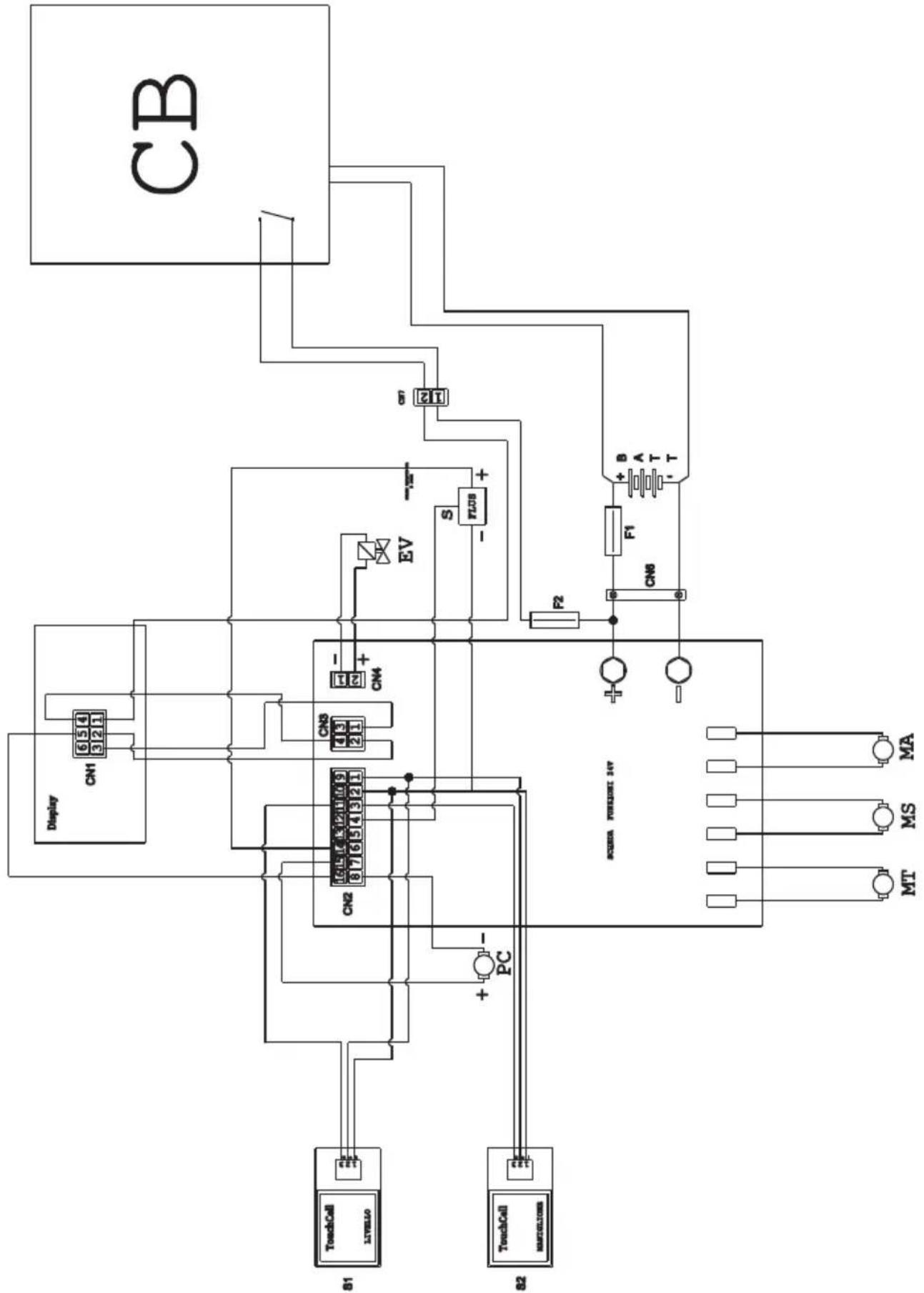
WIRING DIAGRAM
ROUND TOUCH 45 M55 - 45 D55 - 45 D60
flowchart
graph TD
    CB["CB"] -->|Pin 21| S1["21"]
    CB -->|Pin 22| EV["EV"]
    CB -->|Pin 23| F1["F1"]
    CB -->|Pin 24| T["T-T"]
    CB -->|Pin 25| R2["R2"]
    CB -->|Pin 26| CN8["CN8"]
    CB -->|Pin 27| A["A"]
    CB -->|Pin 28| B["B"]
    CB -->|Pin 29| C["A"]
    CB -->|Pin 30| D["B"]
    CB -->|Pin 31| E["C"]
    CB -->|Pin 32| F["C"]
    CB -->|Pin 33| G["C"]
    CB -->|Pin 34| H["C"]
    CB -->|Pin 35| I["C"]
    CB -->|Pin 36| J["C"]
    CB -->|Pin 37| K["C"]
    CB -->|Pin 38| L["C"]
    CB -->|Pin 39| M["C"]
    CB -->|Pin 40| N["C"]
    CB -->|Pin 41| O["C"]
    CB -->|Pin 42| P["C"]
    CB -->|Pin 43| Q["C"]
    CB -->|Pin 44| R["C"]
    CB -->|Pin 45| S["C"]
    CB -->|Pin 46| T["C"]
    CB -->|Pin 47| U["C"]
    CB -->|Pin 48| V["C"]
    CB -->|Pin 49| W["C"]
    CB -->|Pin 50| X["C"]
    CB -->|Pin 51| Y["C"]
    CB -->|Pin 52| Z["C"]
    CB -->|Pin 53| AA["C"]
    CB -->|Pin 54| AB["C"]
    CB -->|Pin 55| AC["C"]
    CB -->|Pin 56| AD["C"]
    CB -->|Pin 57| AE["C"]
    CB -->|Pin 58| AF["C"]
    CB -->|Pin 59| AG["C"]
    CB -->|Pin 60| AH["C"]
    CB -->|Pin 61| AI["C"]
    CB -->|Pin 62| AJ["C"]
    CB -->|Pin 63| AK["C"]
    CB -->|Pin 64| AL["C"]
    CB -->|Pin 65| AM["C"]
    CB -->|Pin 66| AN["C"]
    CB -->|Pin 67| AO["C"]
    CB -->|Pin 68| AP["C"]
    CB -->|Pin 69| AQ["C"]
    CB -->|Pin 70| AR["C"]
    CB -->|Pin 71| AS["C"]
    CB -->|Pin 72| AT["C"]
    CB -->|Pin 73| AU["C"]
    CB -->|Pin 74| AV["C"]
    CB -->|Pin 75| AW["C"]
    CB -->|Pin 76| AX["C"]
    CB -->|Pin 77| AY["C"]
    CB -->|Pin 78| AZ["C"]
    CB -->|Pin 79| BA["C"]
    CB -->|Pin 80| BB["C"]
    CB -->|Pin 81| BC["C"]
    CB -->|Pin 82| BD["C"]
    CB -->|Pin 83| BE["C"]
    CB -->|Pin 84| BF["C"]
    CB -->|Pin 85| BG["C"]
    CB -->|Pin 86| BH["C"]
    CB -->|Pin 87| BI["C"]
    CB -->|Pin 88| BJ["C"]
    CB -->|Pin 89| BK["C"]
    CB -->|Pin 90| BL["C"]
    CB -->|Pin 91| BM["C"]
    CB -->|Pin 92| BN["C"]
    CB -->|Pin 93| BO["C"]
    CB -->|Pin 94| BP["C"]
    CB -->|Pin 95| BQ["C"]
    CB -->|Pin 96| BR["C"]
    CB -->|Pin 97| BS["C"]
    CB -->|Pin 98| BT["C"]
    CB -->|Pin 99| BU["C"]<br>[ACBR CURRENT INV\n>]<br>[ACBR CURRENT INV\n>"]

    subgraph Inputs
        A["Display"] --> B["CN1-CN8"] --> C["CN1-CN8"] --> D["CN1-CN8"] --> E["CN1-CN8"] --> F["CN1-CN8"] --> G["CN1-CN8"] --> H["CN1-CN8"] --> I["CN1-CN8"] --> J["CN1-CN8"] --> K["CN1-CN8"] --> L["CN1-CN8"] --> M["CN1-CN8"] --> N["CN1-CN8"] --> O["CN1-CN8"] --> P["CN1-CN8"] --> Q["CN1-CN8"] --> R["CN1-ClN8"] --> S["CN1-ClN8"] --> T["CN1-ClN8"] --> U["CN1-ClN8"] --> V["CN1-ClN8"] --> W["CN1-ClN8"] --> X["CN1-ClN8"] --> Y["CN1-ClN8"] --> Z["CN1-ClN8"] --> AA["CN1-ClN8"] --> AB["CM"] --> AC["MA"] --> AD["MS"] --> AE["MT"]<br>[ACBR CURRENT INV\n>"]

    style Input fill:#f9f,stroke:#333
    style Output fill:#ccf,stroke:#333
BATT ...... Battery
CB ......Battery charger
CN 1 ......Display connector
CN 2 Card connector
CN 3 ......Display card connector
CN4 ....Chemical pump connector
CN6 Battery connector
CN7 2-pole flying connector battery charger
EV......Solenoid
F1 ...... Fuse
F2 ......Fuse 5A
FLUS ....Flowmeter
MA......Vacuum engine
MS Brush engine
MT ....Traction engine
PC...... Chemical pump
S1 ...... Recovery level touch sensor
S2.....Touch sensor handle
GENERAL SETS = RÉGLAGES GÉNÉRAUX DISPLAY TUNE = LUMINOSITÉ ÉCRAN
GENERAL
SETS
DISPLAY
BIGHTNESS:
GENERAL SETS = RÉGLAGES GÉNÉRAUX DISPLAY BIGHTNESS = RÉGLAGE ÉCRAN
GENERAL SETS = RÉGLAGES GÉNÉRAUX
BATTERY SELECTION = CHOIX DE BATTERIE
GENERAL SETS = RÉGLAGES GÉNÉRAUX
DISPLAY BIGHTNESS = RÉGLAGE ÉCRAN
GENERAL SETS = RÉGLAGES GÉNÉRAUX DISPLAY TUNE = LUMINOSITÉ ÉCRAN
Normale position "A"
Fig. C = position correct
flowchart
Electrical circuit diagram showing connections between components like CB, Display, CN1-CN8, and TouchCell/Mathode with labeled pins and logic gates.BATT ...... Batterie
WET = SÄURE-Batterie
PROBLEMAS - CAUSAS - SOLUÇÕES
flowchart
Electrical circuit diagram showing connections between components like CB, Display, CN1-CN8, and TouchCell/Mathode with labeled pins and logic gates.Vacuum operationeel.
PROBLEEM - OORZAAK - OPLOSSING
MT ....Traction engine
MC .... Chemische pomp
S1 ......Recovery niveau touchsensor
S2.....Touch sensor handvat
7.0 SIKKERHETS PASSORD
Maskinen kan utstyres med en sikkerhets passord; for å aktivere den eller deaktivere den, kan du kontakte teknisk støtte.
ID CHECK = ID SJEKK INSERT PASSWORD = SETT PASSORD
GENERAL SETS = GENERELT SETT DISPLAY TUNE = VISNING TUNE

GENERAL SETS = GENERELT SETT DISPLAY BIGHTNESS = SKJERMENS LYSSTYRKE
GENERAL SETS = GENERELT SETT LANGUAGE SELECTION = SPRÄKVALG
GENERAL SETS = GENERELT SETT DISPLAY BIGHTNESS = SKJERMENS LYSSTYRKE
GENERAL SETS = GENERELT SETT DISPLAY TUNE = VISNING TUNE
12.1 VEDLIKEHOLD OG RENGJ∅RING

ADVARSEL:
- Remonter alt, fortsetter i revers.
OPERASJONER SOM SKAL UTF∅RES INNE N∅D
12.1.e - Rengjøring filter for rent vannr (Fig. 19)

MERK:
flowchart
Electrical circuit diagram showing connections between components like CB, Display, CN1-CN8, and TouchCell/Mathode with labeled pins and logic gates.BATT ...... Batteri
CB ......Batterilader
CN 1 ......Displaykontakt
CN 2 Kortkontakt
CN 3 ....50A stikkontakt
CN4 ...... Connector for pumpe kjemisk
CN6 ...... Batteri-kontakt
CN7 ......Kobling til ratt 2 poler batterilader
EV......Solenoid
F1 Sikring
F2 ......Sikring 5A
FLUS ......Strømningsmåler
MA......Vacuum motor
ID CHECK = ID TJEK INSERT PASSWORD = INESAET PASSWORD
GENERAL SETS = GENEREL SÆT DISPLAY TUNE = SKÆRMENS TUNE

GENERAL SETS = GENEREL SÆT DISPLAY BIGHTNESS = SKÆRMENS LYSSTYRKE
GENERAL SETS = GENEREL SÆT DISPLAY TUNE = SKÆRMENS TUNE
“ECO” = ECO-tilstand
Den viser, när ECO-funktionen er aktiv, med knappen (88) "ECO".
9.1 PÅFYLDNING AF TANK (Fig. 11)

ADVARSEL:
Position for at fjerne snavs "B"
GENERAL SETS = MER ALLMÄNNA
BATTERY SELECTION = BATTERI URVALET
GENERAL
SETS
DISPLAY
TUNE: 33
GENERAL SETS = MER ALLMÄNNA
GENERAL SETS = MER ALLMÄNNA
DISPLAY BIGHTNESS = SKÄRMENS LJUSSTYRKA
GENERAL SETS = MER ALLMÄNNA
LANGUAGE SELECTION = SPRÅKVAL
GENERAL SETS = MER ALLMÄNNA
BATTERY SELECTION = BATTERI URVALET
GENERAL SETS = MER ALLMÄNNA
DISPLAY BIGHTNESS = SKÄRMENS LJUSSTYRKA
GENERAL SETS = MER ALLMÄNNA
flowchart
Electrical circuit diagram showing connections between components like CB, Display, CN1-CN8, and TouchCell/Mathode with labeled pins and logic gates.BATT ...... Batteri
CB ......Batteriladdare
CN 1 ......Displaykontakt
CN 2 Cardkontakt
CN 3 50A utlopp
Professional Cleaning Machines Since 1968
DEALER
GHIBLI & WIRBEL S.p.A.
Registered office:
Via Enrico Fermi, 43 - 37136 Verona (VR) - Italy
Headquarters: