L 1100 125 - Sander Flex - Free user manual and instructions
Find the device manual for free L 1100 125 Flex in PDF.


User questions about L 1100 125 Flex
0 question about this device. Answer the ones you know or ask your own.
Ask a new question about this device
Download the instructions for your Sander in PDF format for free! Find your manual L 1100 125 - Flex and take your electronic device back in hand. On this page are published all the documents necessary for the use of your device. L 1100 125 by Flex.
USER MANUAL L 1100 125 Flex
natural_image
Line drawing of a FLEX angle grinder tool (no text or symbols on the device itself)en Original operating instructions....14
natural_image
Mechanical assembly diagram showing a grinding tool with three circular components and rotational arrows indicating motion (no text or symbols)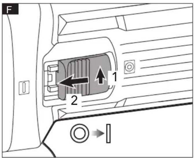
text_image
F 1 2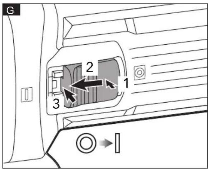
text_image
G 2 1 3
text_image
H I → ○Symbols used in this manual

WARNING!
Denotes impending danger. Non-observance of this warning may result in death or extremely severe injuries.

CAUTION!
Denotes a possibly dangerous situation. Non-observance of this warning may result in slight injury or damage to property.

NOTE
Denotes application tips and important information.
Symbols on the power tool

Before switching on the power tool, read the operating manual!

Wear goggles!

Protection class II (completely insulated)

Disposal information for the old machine (see page 20)!
For your safety

WARNING!
Before using the power tool, please read the follow:
- This appliance can be used by persons with reduced physical, sensory or mental capabilities or lack of experience and knowledge if they have been given supervision or instruction concerning use of the appliance in a safe way and understand the hazards involved.
- Children shall not play with the appliance. Keep the appliance and its cord out of reach of children.
– these operating instructions,
– the currently valid site rules and the regulations for the prevention of accidents.
This power tool is state of the art and has been constructed in accordance with the acknowledged safety regulations.
Nevertheless, when in use, the power tool may be a danger to life and limb of the user or a third party, or the power tool or other property may be damaged.
The angle grinder may be used only
-asintended,
- in perfect working order.
Faults which impair safety must be repaired immediately.
Intended use
This angle grinder is intended
– for commercial use in industry and trade,
– is designed for dry grinding metal and stone,
- For grinding surfaces, for derusting and stripping paint when used with the elastic sanding pad,
– for use with grinding tools and accessories which are indicated in this manual or recommended by the manufacturer,
- for cutting metal, a special protection guard for cutting (accessory) must be used; for cutting stone, a special extraction hood for cutting with cutting guide (accessory) must be used,
– with approved sanding tools, the machine can be used for sanding with sanding discs,
– with approved accessories, the machine can be used for drilling with diamond drills.
Not permissible are e.g. chainsaw discs, saw blades.
Safety instructions for angle grinder
Safety instructions for all operations Safety warnings common for grinding, sanding, wire brushing, polishing or cutting-off operations:
■ This power tool is intended to function as a grinder, sander, wire brush, polisher, hole cutter or cut-off tool. Read all safety warnings, instructions, illustrations and specifications provided with this power tool. Failure to follow all instructions listed below may result in electric shock, fire and/or serious injury.
■ Do not convert this power tool to operate in a way which is not specifically designed and specified by the tool
manufacturer. Such a conversion may result in a loss of control and cause serious personal injury.
- Do not use accessories which are not specifically designed and specified by the tool manufacturer. Just because the accessory can be attached to your power tool, it does not assure safe operation.
■ The rated speed of the accessory must be at least equal to the maximum speed marked on the power tool. Accessories running faster than their rated speed can break and fly apart.
■ The outside diameter and the thickness of your accessory must be within the capacity rating of your power tool. Incorrectly sized accessories cannot be adequately guarded or controlled.
■ The dimensions of the accessory mounting must fit the dimensions of the mounting hardware of the power tool. Accessories that do not match the mounting hardware of the power tool will run out of balance, vibrate excessively and may cause loss of control.
- Do not use a damaged accessory. Before each use inspect the accessory such as abrasive wheels for chips and cracks, backing pad for cracks, tear or excess wear, wire brush for loose or cracked wires. If power tool or accessory is dropped, inspect for damage or install an undamaged accessory. After inspecting and installing an accessory, position yourself and bystanders away from the plane of the rotating accessory and run the power tool at maximum no-load speed for one minute. Damaged accessories will normally break apart during this test time.
■ Wear personal protective equipment. Depending on application, use face shield, safety goggles or safety glasses. As appropriate, wear dust mask, hearing protectors, gloves and workshop apron capable of stopping small abrasive or workpiece fragments. The eye protection must be capable of stopping flying debris generated by various applications. The dust mask or respirator must be capable of filtrating particles generated by the particular application. Prolonged exposure to high intensity noise may cause hearing loss.
- Keep bystanders a safe distance away from work area. Anyone entering the work area must wear personal protective equipment. Fragments of workpiece or of a broken accessory may fly away and cause injury beyond immediate area of operation.
- Hold the power tool by insulated gripping surfaces only, when performing an operation where the cutting accessory may contact hidden wiring or its own cord. Cutting accessory contacting a "live" wire may make exposed metal parts of the power tool "live" and could give the operator an electric shock.
■ Position the cord clear of the spinning accessory. If you lose control, the cord may be cut or snagged and your hand or arm may be pulled into the spinning accessory.
■ Never lay the power tool down until the accessory has come to a complete stop. The spinning accessory may grab the surface and pull the power tool out of your control.
■ Do not run the power tool while carrying it at your side. Accidental contact with the spinning accessory could snag your clothing, pulling the accessory into your body. - Regularly clean the power tool's air vents. The motor's fan will draw the dust inside the housing and excessive accumulation of powdered metal may cause electrical hazards.
■ Do not operate the power tool near flammable materials. Sparks could ignite these materials.
■ Do not use accessories that require liquid coolants. Using water or other liquid coolants may result in electrocution or shock
Further safety instructions for all operations
⚠️ KICKBACK AND RELATED WARNINGS:
Kickback is a sudden reaction to a pinched or snagged rotating wheel, backing pad, brush or any other accessory. Pinching or snagging causes rapid stalling of the rotating accessory which in turn causes the uncontrolled power tool to be forced in the direction opposite of the accessory's rotation at the point of the binding.
For example, if an abrasive wheel is snagged or pinched by the workpiece, the edge of the wheel that is entering into the pinch point can dig into the surface of the material causing
the wheel to climb out or kick out. The wheel may either jump toward or away from the operator, depending on direction of the wheel's movement at the point of pinching. Abrasive wheels may also break under these conditions.
Kickback is the result of power tool misuse and/or incorrect operating procedures or conditions and can be avoided by taking proper precautions as given below.
- Maintain a firm grip on the power tool and position your body and arm to allow you to resist kickback forces. Always use auxiliary handle, if provided, for maximum control over kickback or torque reaction during start-up. The operator can control torque reactions or kickback forces, if proper precautions are taken.
■ Never place your hand near the rotating accessory. Accessory may kickback over your hand. - Do not position your body in the area where power tool will move if kickback occurs. Kickback will propel the tool in direction opposite to the wheel's movement at the point of snagging.
■ Use special care when working corners, sharp edges etc. Avoid bouncing and snagging the accessory. Corners, sharp edges or bouncing have a tendency to snag the rotating accessory and cause loss of control or kickback.
■ Do not attach a saw chain woodcarving blade or toothed saw blade. Such blades create frequent kickback and loss of control.
Additional safety instructions for grinding and cutting-off operations
Safety warnings specific for grinding and cutting-off operations:
■ Use only wheel types that are specified for your power tool and the specific guard designed for the selected wheel. Wheels for which the power tool was not designed cannot be adequately guarded and are unsafe.
■ The grinding surface of center depressed wheels must be mounted below the plane of the guard lip. An improperly mounted wheel that projects through the plane of the guard lip cannot be adequately protected.
■ The guard must be securely attached
to the power tool and positioned for maximum safety, so the least amount of wheel is exposed towards the operator. The guard helps to protect the operator from broken wheel fragments, accidental contact with wheel and sparks that could ignite clothing.
- Wheels must be used only for specified applications. For example: do not grind with the side of cut-off wheel. Abrasive cut-off wheels are intended for peripheral grinding, side forces applied to these wheels may cause them to shatter.
■ Always use undamaged wheel flanges that are of correct size and shape for your selected wheel. Proper wheel flanges support the wheel thus reducing the possibility of wheel breakage. Flanges for cut-off wheels may be different from grinding wheel flanges. - Do not use worn down wheels from larger power tools. A wheel intended for larger power tool is not suitable for the higher speed of a smaller tool and may burst.
■ When using dual purpose wheels always use the correct guard for the application being performed. Failure to use the correct guard may not provide the desired level of guarding, which could lead to serious injury.
Additional safety instructions for cutting-off operations
Additional safety warnings specific for cutting-off operations:
- Do not "jam" the cut-off wheel or apply excessive pressure. Do not attempt to make an excessive depth of cut.
Overstressing the wheel increases the loading and susceptibility to twisting or binding of the wheel in the cut and the possibility of kickback or wheel breakage
■ Do not position your body in line with and behind the rotating wheel. When the wheel, at the point of operation, is moving away from your body, the possible kickback may propel the spinning wheel and the power tool directly at you. - When the wheel is binding or when interrupting a cut for any reason, switch off the power tool and hold it motionless until the wheel comes to a complete stop. Never attempt to remove the cut-
off wheel from the cut while the wheel is in motion otherwise kickback may occur. Investigate and take corrective action to eliminate the cause of wheel binding.
- Do not restart the cutting operation in the workpiece. Let the wheel reach full speed and carefully re-enter the cut. The wheel may bind, walk up or kickback if the power tool is restarted in the workpiece.
■ Support panels or any oversized workpiece to minimize the risk of wheel pinching and kickback. Large workpieces tend to sag under their own weight. Supports must be placed under the workpiece near the line of cut and near the edge of the workpiece on both sides of the wheel. - Use extra caution when making a "pocket cut" into existing walls or other blind areas. The protruding wheel may cut gas or water pipes, electrical wiring or objects that can cause kickback.
■ Do not attempt to do curved cutting. Overstressing the wheel increases the loading and susceptibility to twisting or binding of the wheel in the cut and the possibility of kickback or wheel breakage, which can lead to serious injury.
Additional safety instructions for sanding operations
Safety warnings specific for sanding operations:
■ Use proper sized sanding disc paper. Follow manufacturers recommendations, when selecting sanding paper. Larger sanding paper extending too far beyond the sanding pad presents a laceration hazard and may cause snagging, tearing of the disc or kickback.
Additional safety instructions for polishing operations
Safety warnings specific for polishing operations:
- Do not allow any loose portion of the polishing bonnet or its attachment strings to spin freely. Tuck away or trim any loose attachment strings. Loose and spinning attachment strings can entangle your fingers or snag on the workpiece.
Additional safety instructions for wire brushing operations Safety warnings specific for wire brushing operations:
■ Be aware that wire bristles are thrown by the brush even during ordinary operation. Do not overstress the wires by applying excessive load to the brush. The wire bristles can easily penetrate light clothing and/or skin.
■ If the use of a guard is specified for wire brushing, do not allow any interference of the wire wheel or brush with the guard. Wire wheel or brush may expand in diameter due to work load and centrifugal forces.
Noise and vibration
The noise and vibration values have been determined in accordance with EN 60745.
The A evaluated noise level of the power tool is typically:
– Sound pressure level L_pA : 90 dB(A)
– Sound power level L_WA : 101 dB(A)
- Uncertainty: K = 3 dB
Total vibration value:
- Emission value a_h : 7.8 m/s
- Uncertainty: K = 1.5 m/s
CAUTION!
The indicated measurements refer to new power tools. Daily use causes the noise and vibration values to change.
i NOTE
The vibration emission level given in this information sheet has been measured in accordance with a measurement method standardised in EN 60745 and may be used to compare one tool with another.
That the declared vibration total value(s) and the declared noise emission value(s) may also be used in a preliminary assessment of exposure.
However, if the tool is used for different applications, with different accessories or poorly maintained, the vibration emission level may differ.
This may significantly increase the exposure level over the total working period.
To make an accurate estimation of the vibration exposure level, it is also necessary to take into account the times when the tool is switched off or running but not actually in use.
This may significantly decrease the exposure level over the total working period.
Identify additional safety measures to protect the operator from the effects of vibration such as: maintain the tool and the accessories, keep the hands warm, organisation of work patterns.

WARNING:
- that the vibration and noise emissions during actual use of the power tool can differ from the declared values depending on the ways in which the tool is used especially what kind of workpiece is processed; and
- of the need to identify safety measures to protect the operator that are based on an estimation of exposure in the actual conditions of use(taking account of all parts of the operating cycle such as the times when the tool is switched off and when it is running idle in addition to the trigger time).

CAUTION!
Wear ear protection at a sound pressure above 85 dB(A).
Technical data
| Tool | L 1100125 230/CEE | L 1100125 220-240/BS | |
| Type Angle Grinder | |||
| Rated voltage | V 220-240 | ||
| Frequency Hz | 50/60 | ||
| Input power W | 1100 | ||
| No load speed | /min 1 | 2000 | |
| Wheel type TYPE 27 | |||
| Wheel diameter | mm Φ | 125 | |
| Wheel thickness | mm Max. 6 | ||
| Spindle thread | M14 | ||
| Weight according to“EPTA Procedure 01/2003” | kg | 2.4 2.7 | |
| Working temperature | -10-40°C | ||
| Storage Temperature | -40-70°C | ||
Overview (see figure A)
The numbering of the product features refers to the illustration of the machine on the graphics page.
- Auxiliary handle
- Spindle lock
- Handle
- Switch rocker
- Grinding guard
- Clamping lever
- Inner flange
- Spindle
- Clamping nut
- Face spanner
- Power cord
Operating instructions

WARNING!
Before performing any work on the electric power tool, pull out the mains plug.
Before switching on the power tool
Unpack the angle grinder and check that there are no missing or damaged parts.
Installing and removing the grinding guard (see figure B)

WARNING!
Never work without the guard. Attempting to use grinder with guard removed will result in serious personal injury.

WARNING!
If any parts are damaged or missing do not operate this product until the parts are replaced. Use of this product with damaged or missing parts could result in serious personal injury.

WARNING!
Do not use the guard for cut-off operations.
To install the guard
■ Pull out the mains plug.
■ Loosen the clamping lever (6).
■ Mount the guard with the protrusions (B-2) on the guard aligned with the notches (B-3) on the bearing box.
■ Adjust the position of the guard (5) to meet the requirements of the operation.
■ Retighten the clamping lever (6).
i
NOTE
If the clamping lever (6) is too tight or too loose to fasten the guard, loosen or tighten the screw (B-1) to adjust the tightening of the guard.
To remove the guard
■ Open clamping lever (6).
■ Rotate guard (5) until the two protrusions (B-2) on guard line up with the two notches (B-3).
■ Lift guard (5) off the tool.
Installing and removing the grinding wheel (see figure C & D)
To install the grinding wheel
■ Pull out the mains plug.
■ Press and hold down the spindle lock (2).
■ Using the face spanner (10), loosen the clamping nut (9) on the spindle (8) in an anti-clockwise direction and remove.
■ Insert the grinding wheel in the correct position.
■ Screw the clamping nut (9) with the raised section against the wheel.
■ Press and hold down the spindle lock (2).
■ Tighten the clamping nut (9) with the face spanner (10).
■ Insert the mains plug into the socket.
■ Switch on the angle grinder (without locking into position) and leave the angle grinder running for approx. 30 seconds. Check for imbalances and vibrations.
■ Switch off the angle grinder.
To remove the grinding wheel
■ Depress the spindle lock (2) and rotate the clamping nut (9) until the spindle (8) locks.
■ Loosen and remove the clamping nut (9) from the spindle (8) using the face spanner (10) provided.
■ Remove the grinding wheel.
Auxiliary handle (see figure E)

WARNING!
Always be sure that the auxiliary handle is installed securely before operation.
Screw the auxiliary handle (1) securely on the position of the tool as shown in the figure E.
Switching on and off
Brief operation without engaged switch
rocker (see figure F)
■ Press the switch rocker (4) (1.), push it forwards and hold in position (2.).
■ To switch off the power tool, release the switch rocker (4).
Continuous operation with engaged switch rocker (see figure G &H)
■ Press the switch rocker (4) (1.), push it forwards (2.) and engage by pressing the front end (3.).
■ To switch off the power tool, release the switch rocker (4) by pressing the rear end.
i
NOTE
Following a power failure, the switched on power tool does not restart.
Operating instructions
i
NOTE
When the power tool is switched off, the grinding tool continues running briefly.
!
WARNING!
To maintain proper control, always operate the tool with both hands, keeping one hand on the auxiliary handle. Loss of control could cause an accident resulting in possible serious injury.
Rough-grinding
!
WARNING!
Never use cutting-off wheels for rough-grinding.
!
WARNING!
Always wear safety goggles or a face shield during operation.
!
WARNING!
Always operate with two hands.
- Angle of wheel 20-40° for best cutting performance.
- Applying moderate pressure, move the angle grinder backwards and forwards. As a result, the workpiece will not become too hot and there will be no discoloration, nor will there be any grooves.
Maintenance and care
!
WARNING!
Before carrying out any work on the angle grinder, always pull out the mains plug.
Cleaning
■ Clean the power tool and grille in front of the vent slots regularly. Frequency of cleaning is dependent on the material and duration of use.
■ Regularly blow out the housing interior and motor with dry compressed air.
Carbon brushes
The angle grinder features cut-off carbon brushes. When the wear limit of the cut-off carbon brushes is reached, the angle grinder switches off automatically.
NOTE
Use only original parts supplied by the manufacturer for replacement purposes. If non-original parts are used, the guarantee obligations of the manufacturer will be deemed null and void.
When the power tool is being used, the carbon brushes can be seen sparking through the rear air inlet apertures. If the carbon brushes spark excessively, switch off the angle grinder immediately.
Take the angle grinder to a customer service workshop authorized by the manufacturer.
Gears
NOTE
Do not loosen the screws on the gear head during the warranty period. Non-compliance will deem the guarantee obligations of the manufacturer null and void.
Repairs
Repairs may be carried out by an authorised customer service centre only.
Spare parts and accessories
For other accessories, in particular tools and polishing aids, see the manufacturer's catalogues.
Exploded drawings and spare-part lists can be found on our homepage:
www.flex-tools.com
Disposal information
WARNING!
Render redundant power tools unusable:
- mains operated power tool by removing the power cord,
EU countries only Do not throw electric power tools into the household waste!
In accordance with the European Directive 2012/19/EU on Waste Electrical and Electronic Equipment and transposition into national law used electric power tools must be collected separately and recycled in an environmentally friendly manner.
Raw material recovery instead of waste disposal.
Device, accessories and packaging should be recycled in an environmentally friendly manner. Plastic parts are identified for recycling according to material type.
NOTE
Please ask your dealer about disposal options!
C €-Declaration of conformity
We declare on our sole responsibility that the product described in "Technical specifications" conforms to the following standards or normative documents: EN 60745 in accordance with the regulations of the directives 2014/30/EU, 2006/42/EC, 2011/65/EU. Responsible for technical documents: FLEX-Elektrowerkzeuge GmbH, R & D Bahnhofstrasse 15, D-71711 Steinheim/Murr
Technical Director Head of Quality Department (QD)
Declaration of Conformity
We as the manufacturer: FLEX
declare under our sole responsibility, that the product(s) described under „Technical specifications“ fulfills all the relevant provisions of The Supply of Machinery
(Safety) Regulations S.I. 2008/1597 and also fulfills all the relevant provisions of the following UK Regulations:
Electromagnetic Compatibility Regulations
S.I. 2016/1091, The Restriction of the Use of Certain Hazardous Substances in Electrical and Electronic Equipment Regulations
S.I. 2012/3032 and are manufactured in accordance with the following designated Standards:
BS EN 60745-1:2009+A11:2010
BS EN 60745-2-3:2011+A13:2015
BS EN 55014-1:2017+A11:2020
BS EN 55014-2:2015
BS EN IEC 61000-3-2:2019
BS EN 61000-3-3:2013+A1:2019
Place of declaration: Steinheim, Germany.
Responsible person: Peter Lameli, Technical Director - FLEX-Elektrowerkzeuge GmbH
Contact details for Great Britain: FLEX Power Tools Limited, Unit 8 Anglo Office Park, Lincoln Road, HP 12, 3RH Buckinghamshire, United Kingdom.
Technical Director Head of Quality
Department (QD)
Exemption from liability
The manufacturer and his representative are not liable for any damage and lost profit due to interruption in business caused by the product or by an unusable product.
The manufacturer and his representative are not liable for any damage which was caused by improper use of the product or by use of the product with products from other manufacturers.
22.01.2024
Technical Director Head of Quality Department (QD)
Technical Director Head of Quality Department (QD)