DPH-04 - Vehicle heater MSW - Free user manual and instructions
Find the device manual for free DPH-04 MSW in PDF.

| Product type | Vehicle auxiliary heater |
| Brand | MSW |
| Model | DPH-04 |
| Supply voltage | 12 V DC (9-16 V) |
| Maximum power | 8 kW |
| Fuel | Diesel (gas oil) |
| Fuel consumption | 0.21 – 0.54 L/h |
| Dimensions (L x D x H) | 380 x 150 x 440 mm |
| Weight | 7.9 kg |
| Operating modes | Manual (6 speeds) and automatic (temperature adjustment) |
| Timer | Yes, on/off programming (1-24 h) |
| Remote control | Yes, wireless pairing |
| Altitude mode | Yes, for altitudes >2000 m |
| Display | Control panel with screen and buttons |
| Safety | Overheat protection, automatic shutdown in case of error |
| Maintenance | Clean with a soft, dry cloth, check air ducts regularly |
| Repairability | Repairs by authorized service only |
| Certification | CE, compliant with applicable safety standards |
| Usage | Interior of vehicles, boats, machines (temporary heating) |
| Operating temperature | -40°C to +50°C |
| Fuse | Yes, included in the cable harness |
Frequently Asked Questions - DPH-04 MSW
User questions about DPH-04 MSW
0 question about this device. Answer the ones you know or ask your own.
Ask a new question about this device
Download the instructions for your Vehicle heater in PDF format for free! Find your manual DPH-04 - MSW and take your electronic device back in hand. On this page are published all the documents necessary for the use of your device. DPH-04 by MSW.
USER MANUAL DPH-04 MSW

natural_image
Close-up of a red electronic device with two red probes and black connectors (no visible text or symbols)natural_image
Pure diagram of a mechanical or electrical component with no text, numbers, or symbols1
natural_image
Pure diagram of a pipe system with no text, numbers, or symbols2
1 - Richtig
2 - Falsch
This User Manual has been translated using machine translation. We have made every effort to ensure the translation is accurate, but please note that automated translations are not perfect and are not meant to replace human translators. The official version of the User Manual is in English. Any differences between the translated version and the original English are not legally binding. If you have any questions about the accuracy of the translation, please refer to the English version, which is the official reference. More language versions are available upon request via info@expondo.com.
Technical data
| Parameter description | Parameter value | ||||
| Product name | Parking Heater | ||||
| Model | MSW-DPH-01 | MSW-DPH-02 | MSW-DPH-03 | MSW-DPH-04 | MSW-DPH-05 |
| Supply voltage [V] | 12 | 12 | 12 | 12 | 12 |
| Maximum power [kW] | 5 | 5 | 8 | 8 | 8 |
| Fuel type | Diesel oil | ||||
| Fuel consumption [L/h] | 0,18 – 0,48 | 0,18 – 0,48 | 0,21 – 0,54 | 0,21 – 0,54 | 0,21 – 0,54 |
| Dimensions (width x depth x height) [mm] | 390 x 140 x 170 | 400 x 150 x 420 | 390 x 140 x 170 | 380 x 150 x 440 | 380 x 320 x 240 |
| Weight [kg] | 5.1 | 8 | 5 | 7.9 | 7.9 |
1. General Description
The manual is intended to assist in safe and reliable use. The product is designed and manufactured strictly according to technical specifications using the latest technology and components and maintaining the highest quality standards.
CAREFULLY READ AND UNDERSTAND THIS MANUAL BEFORE STARTING THE WORK.
To ensure the long and reliable operation of the device, make sure to operate and maintain it properly following the guidelines in this instruction manual. The technical data and specifications in this manual are up-to-date. The manufacturer reserves the right to make changes to improve the quality. Taking the technical progress and the possibility of reducing noise into account, the unit is designed and built in such a way that risks resulting from noise emissions are reduced to the lowest possible level.
Explanation of symbols

The product complies with applicable safety standards.
Read the manual before use.
Recyclable product.
CAUTION! or WARNING! or REMEMBER! A general warning sign that describes a given situation.
CAUTION! Fire hazard - flammable materials!
Warning against poisoning by toxic substances!
Caution! Hot surface can cause burns!

CAUTION! The figures in this manual are illustrative only and may vary in some details from the actual appearance of the product.
2. Safety of use

CAUTION! Read all safety warnings and instructions. Failure to follow the warnings and instructions may result in electric shock, fire, and/or serious injury or death.
The term "device" or "product" in the warnings and the description of the instructions refers to Parking Heater
2.1. Electrical safety
a) Do not touch the device with wet or damp hands.
b) Do not use the cord in an unintended manner. Never use it to carry the device or to pull the plug out of the socket. Keep the cord away from heat sources, oil, sharp edges, or moving parts. Damaged or tangled cords increase the risk of electric shock.
c) Do not use the unit if the power cord is damaged or shows signs of wear. A damaged power cord should be replaced by a qualified electrician or the manufacturer's service department.
d) CAUTION – DANGER TO LIFE! When cleaning or using the appliance, never immerse it in water or other liquids.
e) Do not allow the machine to get wet. Risk of electric shock!
f) Before the initial use, please check whether the type of current and mains voltage corresponds to those indicated on the rating plate.
2.2. Safety in the workplace
a) Do not use the unit in an explosive area, for example in the presence of flammable liquids, gases, or dust. The unit produces sparks that can ignite dust or fumes.
b) If you have any doubts as to whether the unit is working properly or if it is damaged, contact the manufacturer's service department.
c) Repairs to the device may only be carried out by the manufacturer's service. Do not attempt to repair the product on your own!
d) In case of open flames or fire, use only dry powder or snow (CO2) fire extinguishers to extinguish the live equipment.
e) Use the product in a well-ventilated area.
f) Do not cut off the fuel supply by squashing or bending the fuel lines.
g) Check the condition of the safety stickers regularly. If the stickers are illegible, they must be replaced.
h) Keep these instructions for use for future reference. If the unit is to be passed on to third parties, the operating instructions must also be handed over together with the unit.
i) Keep packaging components and small installation parts out of the reach of children.
j) Keep the device away from children and animals.
k) When using this product together with other devices, also follow the other instructions for use.

Remember! Keep children and other bystanders safe while operating the appliance.
2.3. Personal safety
a) The product is not intended to be used by individuals (including children) with reduced mental, sensory or intellectual capacity or lack of experience and/or knowledge, unless they are supervised by an individual responsible for their safety or have been given instructions by the responsible individual on how to operate the product.
b) Please be attentive and use common sense when operating this equipment. A moment's inattention during operation may result in serious personal injury.
c) Before switching the unit on, remove any regulating tools or keys. Any tools or keys left in the rotating part of the unit may cause injury.
d) The product is not a toy. Children should be watched to ensure that they do not play with the product.
e) Do not place your hands or any objects inside the running device!
2.4. Safe use of the device
a) Do not overload the device. Use tools that are suitable for the application. A correctly selected unit will do a better and safer job for which it was designed.
b) Do not use the device if the "ON / OFF" switch does not work properly (does not turn the device on and off). Units that cannot be controlled by the switch are unsafe, cannot operate, and must be repaired.
c) Disconnect the device from the power supply before adjusting, cleaning, or servicing. This precaution reduces the risk of accidental start-up.
d) Keep the unit in good working condition. Check before each use for general damage or damage to moving parts (cracks in parts and components or any other condition that may affect the safe operation of the device). If damaged, return the device for repair before use.
e) Keep the product out of the reach of children.
f) Repairs and maintenance should be carried out by qualified personnel using only original spare parts. This will ensure the safety of use.
g) To ensure the designed operational integrity of the device, do not remove factory-installed covers or loosen screws.
h) Do not move, shift, or rotate the device while in operation.
i) Do not leave the device switched on unattended.
j) Clean the device regularly to prevent permanent dirt build-up.
k) Use air to power the unit, no other gases are allowed.
I) The air supplied to the machine should be dehumidified, clean, and free of contaminants. Contaminants can clog hoses and cause damage to the machine and its components.
m) If you notice any leakage from the machine or hoses, immediately disconnect the power supply and correct the fault.
n) Do not exceed the recommended supply pressure as this may damage the unit.
o) Do not obstruct the air inlet or outlet.
p) The product is not a toy. Cleaning and maintenance must not be performed by children without adult supervision.
q) Do not tamper with the device to alter its performance or design.
r) Keep the unit away from sources of fire and heat.
s) Do not block the ventilation openings of the unit!
t) CAUTION! Some parts of the unit become very hot during operation - there is a danger of burning!
u) The device is suitable only for use inside vehicles, boats or machines. It is intended only for temporary heating of the interior.
v) Use only diesel fuel to power the unit.

CAUTION! Although the product has been designed to be safe, with adequate safeguards, and despite the additional safety features provided to the user, there is still a slight risk of accident or injury when handling the unit. Caution and common sense are advised when using the product.
3. Instructions for use
The device is designed for installation in vehicles. The device is designed to heat e.g. vehicle cabins.
The device is not approved for direct heating of the loading compartments of vehicles subject to ADR regulations (transport of dangerous goods).
The user is responsible for any damage resulting from misuse.
3.1. Product overview
MSW-DPH-01 / MSW-DPH-03
The description showcases the model MSW-DPH-01. The MSW-DPH-03 model has a similar appearance.
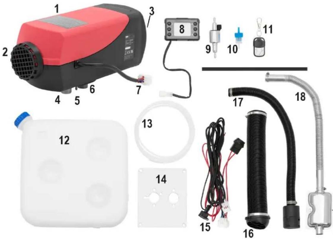
1 - Main unit of the device
2 - Cold air inlet
3 - Hot air outlet (on the back of the device)
4 - Combustion air inlet
5 - Connection of the fuel line
6 - Exhaust outlet
7 - Control panel connection block
8 - Control panel
9 - Fuel pump
10 - Fuel filter
11 - Remote control
12 -Fuel tank
13 - Fuel line
14 - Metal template for fixing the main unit of the machine
15 - Wiring harness
16 - Hot air outlet pipe
17 - Cold air inlet pipe
18 - Exhaust gas outlet pipe with silencer
Electrical wiring harness

1 - Control panel connection block
2 - Fuel pump connection block
3 - Main unit connection block
4 - Fuse
5 - The red wire must be connected to the positive terminal of the car battery
6 - The black wire must be connected to the negative terminal of the car battery
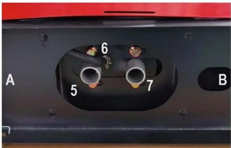
MSW-DPH-02 / MSW-DPH-04 / MSW-DPH-05
The description showcases the model MSW-DPH-02. The MSW-DPH-04 and MSW-DPH-05 models have a similar appearance.
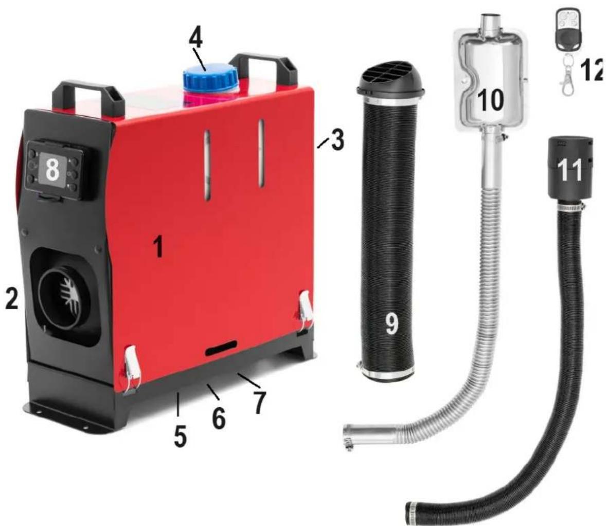

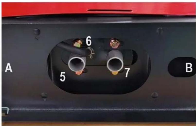
A - Back of the device
B - Front of the device
1 - Main unit of the device
2 - Cold air inlet
3 - Hot air outlet (on the back of the device)
4 - Fuel filler cap
5 - Combustion air inlet (underneath the unit)
6 - Connection of the fuel line (underneath the device)
7 - Exhaust outlet (underneath the unit)
8 - Control panel
9 - Hot air outlet pipe
10 - Exhaust gas outlet pipe with silencer
11 - Cold air inlet pipe
12 - Remote control
Connect the device to the power supply:
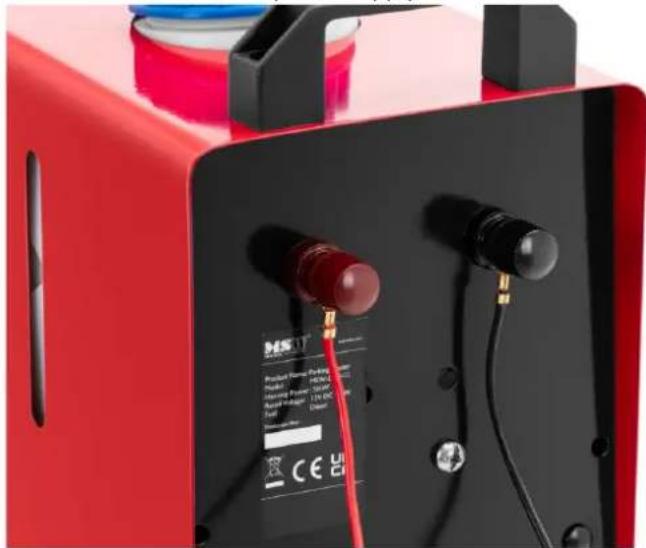
natural_image
Red industrial testing device with red connectors and black buttons (no visible text or symbols)The red pole should be connected to the positive pole of the car battery; the black pole to the negative pole.
Control panel:
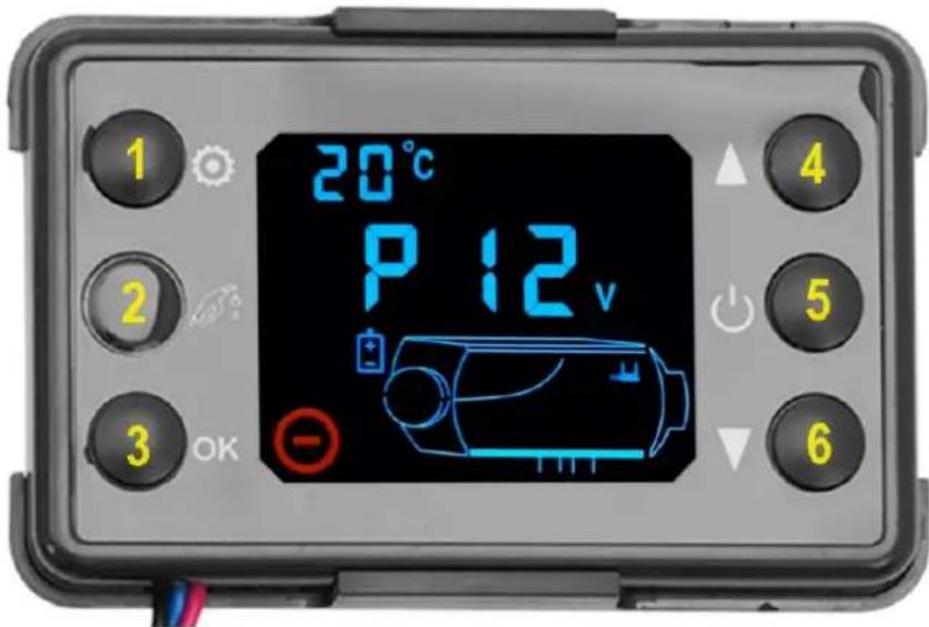
1 - Settings button
2 - Button for manual pumping of the fuel pump
3 - Button for confirming settings / switching between functions
4 - "Up" setting button
5 - ON/OFF switch
6 - "Down" setting button
Starting
In the off state, a long press of the button ⏻ for 2 seconds will start the device and display the boot status as shown below:
Unit shutdown state
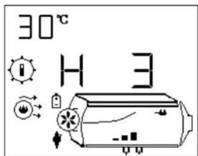
Launch status - manual operation mode
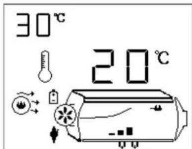
Launch status - automatic operating mode
Switching off
In idle status, press and hold the button for 2 seconds, the unit enters the blowing and cooling process and is displayed. After cooling down, the device will turn off.
During this time, do not force the device to turn off in the cooling process. Direct power failure can damage parts because the unit temperature is too high to dissipate heat. The power can only be cut off when the unit is turned off.
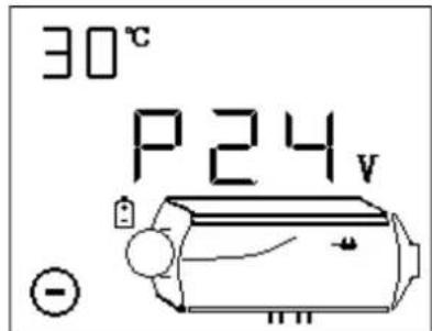
Manual mode
Manual mode has six gears (H1-H6) (or eight gears H1-H8 depending on the model). The H6 / H8 represents the maximum power as shown above. In the starting state, the level can be changed by adding or subtracting gears via the "up" / "down" buttons.
Automatic operating mode
The figure above shows the 20°C setting. The temperature value can be changed with the setting buttons "up" / "down". Switching between manual and automatic modes: long press on the setting button ✿.
Operation of manual pumping of fuel.
In the turned off state, press the setting buttons "up" / "down" simultaneously or press the manual pumping button only for 2 seconds. Manual pumping will be performed and will stop when the button is released. Use with caution.
Plateau mode.
Press the settings button ✪ at the same time as the "OK" button for 2 seconds to switch to the "plateau" mode. The sign ⚠ will appear on the display. To exit plateau mode, press and hold the same two buttons simultaneously. This mode is recommended to be used above an altitude of 2000 m above sea level. In this mode, the fuel-to-air ratio is reduced to accommodate hypoxia at high altitudes.
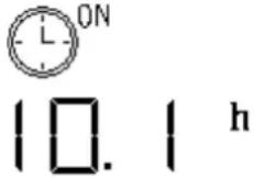
Setting the time switch operation time.
Press and hold the "OK" button and the "down" button simultaneously for two seconds. It will enter the time configuration interface. The display will show the hour value and the icon will flash, the ON sign will be displayed. If the display shows OFF, it means that the shutdown time has been set:
-
Press the setting button "Up" / "Down" to adjust the time value, time range: 1-24 hours.
-
Briefly press the ON / OFF button Ⓧ to switch between the numbers to be set.
-
Briefly press the settings button ✿ to switch between startup and shutdown times.
-
Briefly press the "OK" button to save the settings and exit the interface.
-
Press the settings button ✿ for 2 seconds to exit the interface without saving the settings.
-
Start/stop timer functions. Press and hold the settings button ✦ at the same time as the setting button "up" to start the timer function. The timer will start in the timer for turning on in the off state and the timer off in the on state. "ON" or "OFF" will be flashing, "ON" means temporary launch and "OFF" means temporary shutdown. Briefly press the settings button "*" to display the remaining time.
Pairing the remote control
In the off state, simultaneously press and hold the ON/OFF button ⏻ and the set "down" button for 2 seconds to enter the remote control pairing mode as shown below:

-
Press the "Up"/"Down" setting buttons to set the third digit of the remote control coding, a number from 1 to 5 for the five remote controls respectively.
-
After selecting the desired remote control number, press any button on the remote control to pair it with the device and exit the pairing mode.
Error codes
As shown below, the corresponding error symbol and the corresponding device component symbol flash. The displayed data represents the error code. Their meaning can be found in the error table. Flashing
symbols of a spark plug, pump, fan, power supply and others indicate a failure of the corresponding element of the device.

| Error code | Reason Solution | |
| E-2 Supply voltage failure | 1. Normal range: 12V (9-16V);2. Check that the battery or generator is fine and that the fuse is in working order. | |
| E-3 Glow plug failure | 1. Check that the glow plug connector is not loose or the wire is not shorted to the housing;2. Check that the glow plug is not damaged. | |
| E-4 Pump failure | Inspect the pump cable and connector for damaged, loose, oxidized, shorted, or damaged fragments. | |
| E-5 | High temperature alarm (inlet>50°C; housing>230°C) | 1. Check that the heating air canal is not obstructed;2. Check that the fan is operating normally;3. Check that the temperature sensor is working properly. |
| E-6 Fan failure | 1. Check that the rotor is not blocked;2. Check that the connector is not loose;3. The distance between the magnet on the wheel and the Hall sensor on the controller is too large;4. Check that the circuit is not short-circuited or broken. | |
| E-8 | Flame | 1. Check if the amount of diesel fuel is sufficient, if the oil has not solidified at low temperature, if the oil flow is blocked or if the diesel pump is blocked;2. Check that the intake and exhaust air canals are not obstructed;3. Check that the temperature sensor on the housing is in full contact with the housing and that the compression spring is firm. |
| Unsuccessful startup | 1. The housing temperature is too high and the housing cannot be blown cold after 3 minutes after startup.2. There is a lot of white smoke in the exhaust gas.2.1 Check that the filter next to the spark plug is clean, clean it or replace it if it is dirty;2.2 Check that the oil pump has a strong fuel injection;2.3 Check that the spark plug has not aged.3. Little or no white smoke comes out of the exhaust.3.1 Check for insufficient oil, frozen or blocked oil channel;3.2 Check that the oil pump is not blocked or damaged and cannot pump oil;3.3 Check that the exhaust gas inlet and outlet ducts are not obstructed;3.4 Check that the glow plug is not damaged;3.5 Check that the gap between the inner wind wheel is not too large.4. The ignition is normal but the ignition failure error is still reported.Check that the temperature sensor on the housing is in full contact with the housing, that the compression spring is strong, and that the sensor is normal. | |
| E-9 Sensor failure | Check that the temperature sensor connection cable and connector are not damaged or loose, then check that the sensor is not damaged. | |
It is forbidden to use the machine near devices with high humidity, conductive dust, flammable and explosive gases, dust, materials, corrosive media, strong light, strong magnetic field, high voltage.
Supply voltage range: DC24V controller is suitable for (18-32) V DC; DC12V controller is suitable for (9-16) V DC. Controllers with different voltages are not universal and it is forbidden to use them outside the appropriate voltage range.
3.2. Preparation for operation
The heater can be installed outside and inside the vehicle.
Installation location outside the vehicle:
• The amount of space required by the unit must be provided:
- Space required for hot air outlet: >80 mm.
- Space required for cold air inlet: >45 mm.
-
Space required for removing the heater: >250 mm
-
The place of installation must be protected against mechanical damage.
- The place of installation must be as protected against splashing and sprayed water as much as possible.
- The place of installation must be above the maximum water gauge of the vehicle.
- The combustion air inlet and the flue gas outlet must be separated from each other (to prevent suction of flue gases).
Place of installation inside the vehicle
• The amount of space required by the unit must be available.
- Space required for hot air outlet: >80 mm.
- Space required for cold air inlet: >45 mm.
- Space required for removing the heater: >250 mm
- The connections for the combustion air and exhaust system must be completely on the outside of the vehicle.
- The place of installation must be protected against mechanical damage.
• People must be protected from contact with hot surfaces. Install a contact guard if necessary. - High-temperature-sensitive components must be protected against high temperatures. Install a heat shield if necessary.
3.3. Installation of the unit
The assembly personnel must be qualified to work on technical systems.
Mounting position
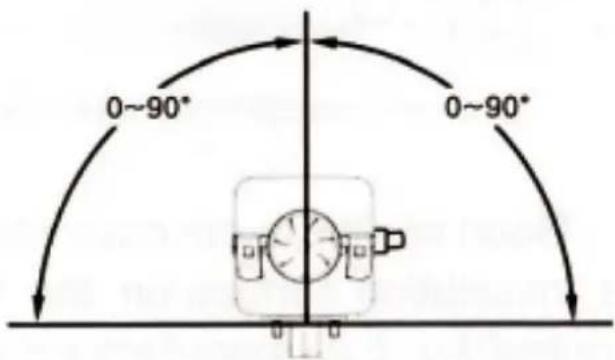
WARNING
The emission of exhaust gases.
Poisoning and suffocation.
Make sure that the housing adheres only to the base of the unit after installation.
Make sure the housing gasket is properly installed.
Make sure that the exhaust gases are discharged only to the outside of the vehicle.
The support surface of the base of the unit must be flat.
Installation of the device - applies to MSW-DPH-01 / MSW-DPH-03
Make sure that the place of installation meets all requirements.
Ensure the correct installation position.
The vehicle manufacturer's requirements must be met.
For unevenness> 1 mm: level the backrest surface.
Make holes using a metal hole pattern.
Install the base gasket between the heater and the contact surface.
Fasten the heater to the base with the nuts.
Make sure that the heater rests on the base.
Cold and hot air system
The cold and hot air system of the heater must not be combined with externally controlled ventilation systems (e.g. vehicle air conditioning).
Recirculated and recirculated air mode:
Cold air can be taken from the atmosphere (open circuit) or from inside the vehicle (closed circuit).
Cold air inlet and hot air outlet
CAUTION
The danger of burns if the distance between the hot air outlet and people is too small.
Make sure people are protected from contact with hot surfaces.
Make sure that people are protected against direct hot air flow from the heater.
The cold air inlet must be set up in such a way that hot air cannot be directly drawn in from the heater or the vehicle's heating system.
1 - Correct
2 - Incorrect
When the external heating air duct is connected to the heater, the duct diameter should not be less than 85 mm. The material of the cable should be resistant to a temperature of 130^ C. The maximum pressure drop between the inlet and outlet sides of the air heating system should not be greater than 0.151 kPa.
Hot air from the heating system should not flow to parts that are not heat resistant. In passenger vehicles, the vent should not be obstructed by passengers. If necessary, you can install a protective net on your own. In the case of the heater operating in external circulation mode, the position of the air inlet opening should be appropriate to ensure that no water splashes or exhaust fumes are sucked into the heater during normal operation.
In the case of the heater operating in the internal circuit, measures must be taken to prevent the supply of hot air from re-entering the air inlet port. If the air inlet pipe is not connected in this mode, a hood with grilles should be installed on the air inlet port of the main heater. The intake air should be taken from a cold area of the compartment, e.g. from under the seats.
Fuel supply
The fuel for the heater can be supplied from the vehicle's fuel tank or from an additional, independent fuel tank. Do not install the fuel tank in the cabin or passenger compartment or in any other place that may cause a fire if an independent fuel tank is used.
The difference in height between the heater and the fuel pump and between the fuel pump and the heater creates fuel pressure in the fuel pump. The inner diameter and length of the fuel line are related to the resistance in the fuel path. Take these factors into account when installing.
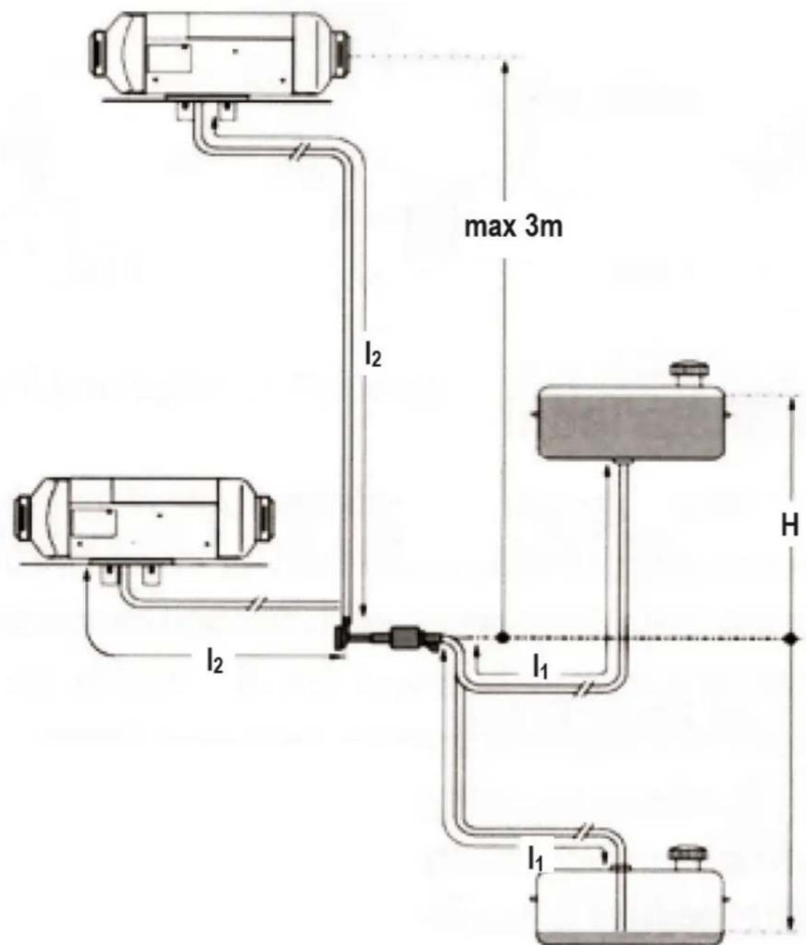
I_1 + I_2 ≤ 10m
I_1 ≤ 1.2m
I_2 ≤ 8.8m
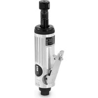
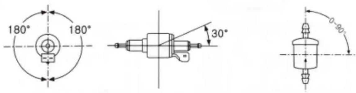
Installation of the fuel pump - applies to MSW-DPH-01 / MSW-DPH-03
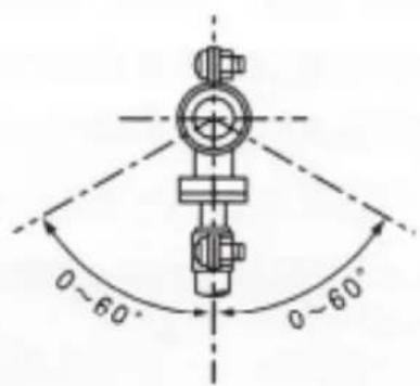
The fuel pump should be installed in places where it is possible to avoid thermal radiation from parts of the vehicle that may emit heat and in places with cool air. Instructions for installing the fuel pump are shown in the figure below. When installing the fuel pump, use the fuel pump bracket supplied with the heater to hold the pump firmly. The pump is secured with a shock-reducing clamp. The place of installation of the pump must be close to the fuel tank so that the fuel suction line is as short as possible. The place of installation must be protected against stone chipping.
Installing the fuel filter
The fuel filter should be installed upstream of the fuel inlet port. Make sure the fuel flow is correct. Its position should be as shown in the figure above.
Installation of the fuel line
Use only steel and plastic hoses made of light- and heat-resistant plastic in accordance with the requirements of DIN 73378 as fuel lines. The inner diameter of the cable is 2 mm.
The fuel line should be located away from flying stones and parts of the vehicle that emit heat. If necessary, the protective device can be locked.
The fuel line from the fuel pump to the primary heater should be oriented in any direction other than downward. The fuel line should be tied in a suitable place to keep it stationary. The distance between the two ties should be less than 50 cm.
The fuel line fittings supplied with the heater should be used for the connections between the fuel line and the fuel pump, the fuel line and the heater, the fuel line and the suction line of the fuel tank, and the fuel line and reducer. The fuel line should be tied with the fuel line clamps. Air bubbles should be removed from the connection points.
1 - Clamp for fuel line
2 - Fuel line
3 - Connection piece
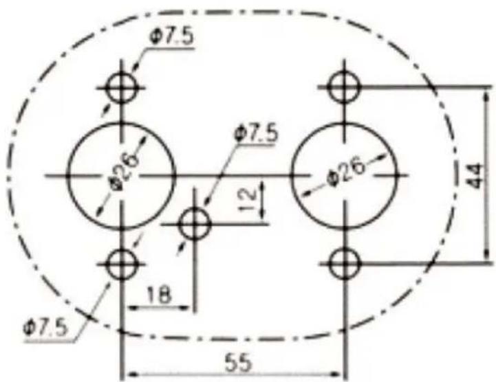
Installation of the fuel extraction device
The holes in the fuel tank (or tank cap) for installation should be of the correct size, with trimmed edges, and evenly spaced around the hole. The lower end of the fuel line should be 30-40 mm from the bottom of the fuel tank to suck in enough fuel and at the same time to avoid sucking in dirt deposited on the bottom of the fuel tank.
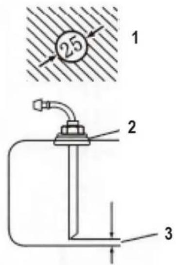
1 - Hole diameter [mm]
2 - For use with metal fuel tanks only
3 - The minimum distance is 25 mm.
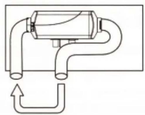
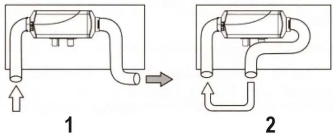
If fuel is taken by the fuel line to the engine, the fuel line from the fuel tank to the fuel filter should be disconnected and reconnected with the thicker T reducer pipes. The thinner T reducer pipe should connect the heater fuel pump with the fuel line fitting and the pipe. The installation angle must be according to the figure below: otherwise, the normal operation of the heater will be disturbed.
After installation, start the vehicle engine, and then turn it off after a minute of operation to remove air trapped in the fuel suction line.
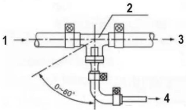
1 - Direction from the fuel tank
2 - Tee
3 - Direction to the fuel filter, vehicle fuel pump and engine
4 - Direction to the heater fuel pump
Installation of the combustion air intake pipe and the gas discharge pipe
The combustion air must be drawn in as fresh air from the outside of the vehicle. The exhaust gases from the combustion process must be discharged into the air through the exhaust pipe. Measures must be taken to prevent exhaust gases from entering the vehicle again.
The cables pass through the outer wall or openings at the bottom of the vehicle. Measures must be taken to prevent the ingress of water splashes. The cables must be secured and permanently shockproof.
Only the air inlet hose and the exhaust hose supplied with the heater may be used. The air intake pipe is a corrugated pipe made of aluminium pipe, the surface of which is covered with plastic and paper. The exhaust pipe is a corrugated stainless steel pipe. You need to identify them and not make a mistake during installation.
To connect them to the heater, use the provided clamps to securely attach them to the combustion air inlet and the exhaust pipe vent, respectively. The protective hood on the air inlet and exhaust outlet openings must be kept in good condition. It must not be damaged or removed.
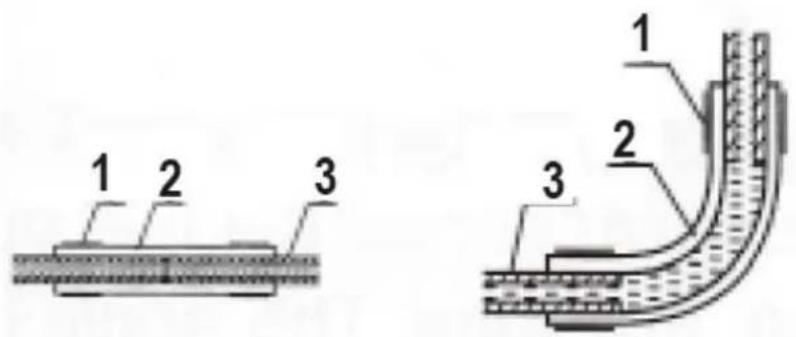
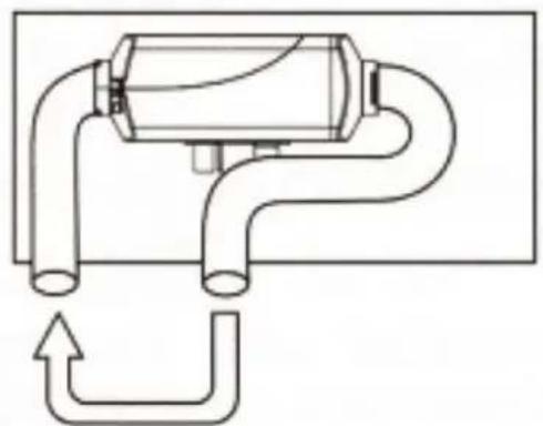
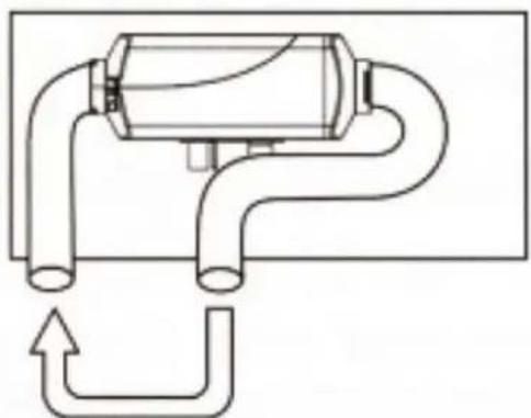
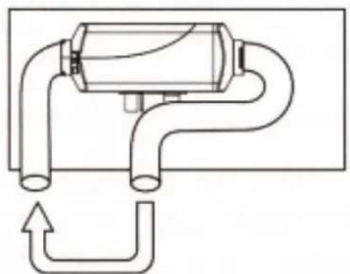
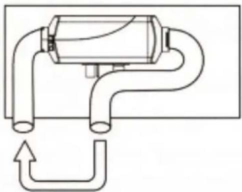
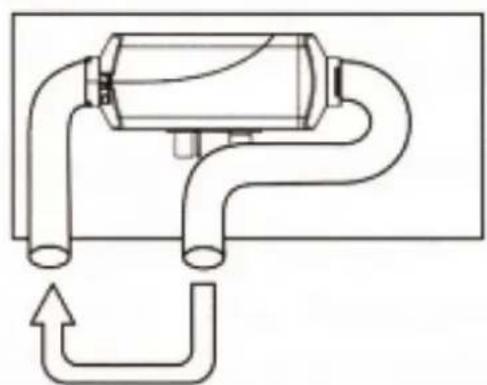
Both the air inlet pipe and the outlet pipe should extend downwards from the heater, otherwise prepare a hole at the bottom of the pipe to drain the condensation water if the pipe needs to be bent.
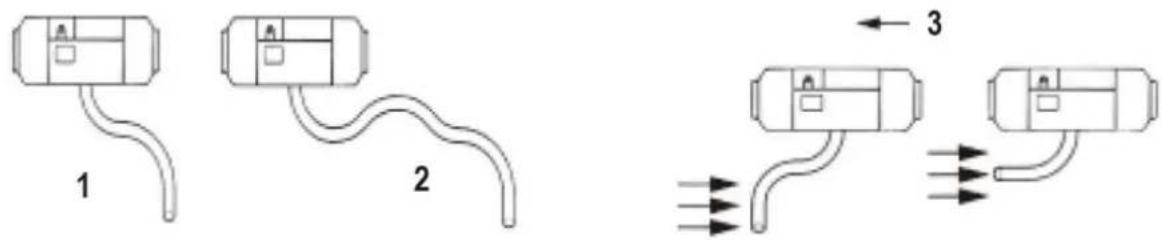
1 - Correct
2 - Incorrect
3 - Direction of vehicle movement
The openings of the pipes should not face the direction of travel of the vehicle.
The cable openings should not be blocked by sludge, rain, snow or other debris.
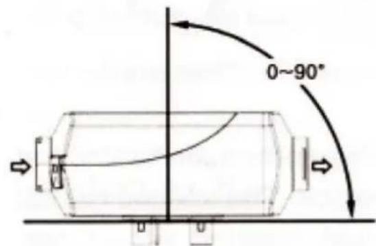
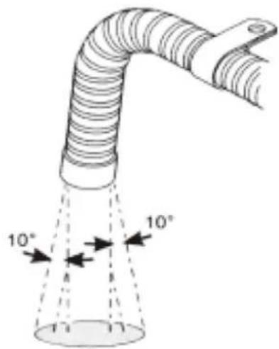
The exhaust pipe should be installed at a distance from plastic parts or other elements of the vehicle body with low thermal resistance. The exhaust pipe should be properly attached. The outlet should be facing downwards, perpendicular to the road surface. To ensure such an angle, the immersion of the exhaust pipe mount should be 150 mm from the end of the pipe.
3.4. Cleaning and maintenance
a) Use only non-corrosive cleaning agents for cleaning the surfaces.
b) After each cleaning, all parts should be thoroughly dried before the device is reused.
c) Store the unit in a dry and cool place protected from moisture and direct sunlight.
d) Do not spray the unit with a stream of water or immerse it in water.
e) Make sure that no water enters through the ventilation openings in the casing.
f) Clean the ventilation openings with a brush and compressed air.
g) Perform regular inspections of the unit checking technical fitness and any damages.
h) Use a soft, damp cloth for cleaning.
i) Do not use sharp and/or metal objects (e.g. wire brush or metal spatula) as they may damage the surface of the material from which the appliance is made.
j) Do not clean the unit with acidic substances, medical agents, thinners, fuel, oils, or other chemicals. It may cause damage to the device.
DISPOSAL OF USED UNITS.
At the end of its useful life, this product should not be disposed of with normal household waste but should be taken to a collection point for the recycling of electrical and electronic equipment. This is indicated by
the symbol on the product, operating instructions, or packaging. The materials used in this appliance are recyclable according to their marking. By reusing, recycling, or applying other forms of use of waste machines, you make a significant contribution to the protection of our environment.
Your local administration will provide you with information about the appropriate disposal point for used appliances.

natural_image
Red and black electronic device with attached earphones and cables (no visible text or symbols)natural_image
Pure diagram of a mechanical or electrical component with no text, numbers, or symbols1
natural_image
Pure diagram of a pipe system with no text, numbers, or symbols2
1 - Poprawnie
2 - Niepoprawnie

natural_image
Red and black electronic device casing with attached test probes and cables (no visible text or symbols)
natural_image
Red industrial testing device with red connectors and a blue cylindrical component (no visible text or symbols)natural_image
Pure diagram of a mechanical or fluidic device with pipe connections and directional arrows, no text or symbols present.1
natural_image
Pure diagram of a mechanical pipe system with no text, numbers, or symbols2
1 - Correct
2 - Incorrect

natural_image
Close-up of a red electronic device with two red connectors and black buttons, no visible text or symbols on the main body.natural_image
Pure diagram of a mechanical or electrical component with no text, numbers, or symbols1
natural_image
Pure diagram of a pipe system with no text, numbers, or symbols2
1 - Corretto
2 - Non corretto

natural_image
Close-up of a red electronic device with two red probes and black connectors (no visible text or symbols)natural_image
Pure diagram of a mechanical or fluidic device with pipe connections and directional arrows, no text or symbols present.1
natural_image
Pure diagram of a mechanical or fluidic device with no text, numbers, or symbols2
1 - Correct
2 - Incorrect

natural_image
Red industrial testing device with red connectors and a blue cylindrical component (no visible text or symbols)natural_image
Pure diagram of a mechanical or fluidic device with pipe connections and directional arrows, no text or symbols present.1
natural_image
Pure diagram of a pipe system with no text, numbers, or symbols2
1 - Helyes
2 - Helytelen