
DCPS330 - Cordless drill DEWALT - Free user manual and instructions
Find the device manual for free DCPS330 DEWALT in PDF.

| Product Type | Cordless Screed Leveler |
| Brand | DeWalt |
| Model | DCPS330 |
| Battery Type | Li-Ion |
| Weight (without battery pack) | 13.8 kg |
| Recommended Battery | DCBPS0554 (5.3 kg) |
| FLEXVOLT Battery Adapter | DCAFVPS (for DCB546/547/548/549) |
| Compatible Screed Length | 1.2 m to 5 m |
| Screed Hole Spacing | 228 mm |
| Bluetooth Transmitter | Band 2400 MHz, max power 2.0 mW |
| Sound Pressure Level (LPA) | 79 dB(A) |
| Sound Power Level (LWA) | 92 dB(A) |
| Sound Uncertainty (K) | 3 dB(A) |
| Max Emitted Vibration (ah) | 5.3 m/s² |
| Vibration Uncertainty (K) | 1.5 m/s² |
| Compatible Screed Types | L-shaped screed, triangular screed, Multivibe screed |
| Speed Control Trigger | With speed lock |
| Parking Stand | Yes, foldable |
| Lifting Points | Frame crossbeam |
| Button Cell Battery | CR2450, 3V |
| Cleaning | Damp cloth with mild soap; do not immerse |
| Storage Temperature | 0 °C to 45 °C |
| Warranty | See full manual |
Frequently Asked Questions - DCPS330 DEWALT
User questions about DCPS330 DEWALT
0 question about this device. Answer the ones you know or ask your own.
Ask a new question about this device
Download the instructions for your Cordless drill in PDF format for free! Find your manual DCPS330 - DEWALT and take your electronic device back in hand. On this page are published all the documents necessary for the use of your device. DCPS330 by DEWALT.
USER MANUAL DCPS330 DEWALT
English (original instructions) 21
natural_image
Icon of a person using a computer (no text or symbols)Fig. A
natural_image
Technical line drawing of a mechanical assembly with no visible text or symbolsFig. UFig. T
DEWALT POWERSHIFT™ ELEKTRISK AFRETTER TIL BETON DCPS330

Vice-President Engineering, PTE-Europa
WARNING: Read all safety warnings, instructions,
illustrations, and specifications in this manual,

including the battery and charger sections provided in an original tool manual or the separate Batteries and
Chargers manual. Manuals can be obtained by contacting
Customer Service (refer to the back page of this manual).
Technical Data
| Type 1 | ||
| Battery type Li-lon | ||
| Weight (without battery pack) kg 13.8 | ||
| Vibration emission value ah = maximum m/s | 2 | 3.7 |
| Uncertainty K = maximum m/s | 2 | 1.5 |
| Beam length m 1.2 - 5 | ||
| L-shaped beam (sold separately) | ||
| Space between holes mm 228 | ||
| Bluetooth** Transmitter | ||
| Frequency band MHz 2400 | ||
| Max. power (EIRP) | mW | 2.0 |
| Noise values and vibration values (triax vector sum) | ||
| LPA (emission sound pressure level) | dB(A) | 79 |
| LWA (sound power level) | dB(A) | 92 |
| K (uncertainty for the given sound level) | dB(A) | 3 |
| Vibration emission value ah = | maximum m/s2 | 5.3 |
| Uncertainty K = | maximum m/s2 | 1.5 |
*The Bluetooth® word mark and logos are registered trademarks owned by the Bluetooth SIG, Inc., and any use of such marks by DEWALT is under license. Other trademarks and trade names are those of their respective owners.
The vibration and/or noise emission level given in this information sheet has been measured in accordance with a standardised test given in EN62841-1 / EN500-4 using wet concrete and may be used to compare one tool with another. It may be used for a preliminary assessment of exposure.
WARNING: The declared vibration and/or noise emission level represents the main applications of the tool. However, if the tool is used for different applications, with different accessories or is poorly maintained, the vibration and/or noise emission may differ. This may significantly increase the exposure level over the total working period. An estimation of the level of exposure to vibration and/or noise should also take into account the times when the tool is switched off or when it is running but not actually doing the job. This may significantly reduce the exposure level over the total working period.
Identify additional safety measures to protect the operator from the effects of vibration and/or noise such as: maintain the tool and the accessories, keep the hands warm (relevant for vibration), organisation of work patterns.
EC-Declaration of Conformity
Machinery Directive and Radio
Equipment Directive

DEWALT POWERSHIFT™ Concrete Power Screed DCPS330
DEWALT declares that these products described under Technical Data are in compliance with:
2006/42/EC, EN62841-1:2015+A11:2022, EN 12649:2008 + A11:2011, EN ISO 12100:2010.
These products also comply with Directive 2014/53/EU and 2011/65/EU.
The full text of the EU declaration of conformity can be requested at below address or is available at the following internet address: www.2helpu.com (search by the Product and Type Number indicated on the nameplate).
For more information, please contact DEWALT at the following address or refer to the back of the manual.
The undersigned is responsible for compilation of the technical file and makes this declaration on behalf of DEWALT.

Markus Rompel
Vice-President Engineering, PTE-Europa
65510, Idstein, Germany
31.12.2024
WARNING: To reduce the risk of injury, read the instruction manual.
Definitions: Safety Guidelines
The definitions below describe the level of severity for each signal word. Please read the manual and pay attention to these symbols.
RANGER: Indicates an imminently hazardous situation which, if not avoided, will result in death or serious injury.
WARNING: Indicates a potentially hazardous situation which, if not avoided, could result in death or serious injury.
AUTION: Indicates a potentially hazardous situation which, if not avoided, may result in minor or moderate injury.
NOTICE: Indicates a practice not related to personal injury which, if not avoided, may result in property damage.
Denotes risk of electric shock.
Denotes risk of fire.
GENERAL POWER TOOL SAFETY WARNINGS
WARNING: Read all safety warnings, instructions, illustrations and specifications provided with this power tool. Failure to follow all instructions listed below may result in electric shock, fire and/or serious injury.
SAVE ALL WARNINGS AND INSTRUCTIONS FOR FUTURE REFERENCE
The term "power tool" in the warnings refers to your mains-operated (corded) power tool or battery-operated (cordless) power tool.
1) Work Area Safety
a) Keep work area clean and well lit. Cluttered or dark areas invite accidents.
b) Do not operate power tools in explosive atmospheres, such as in the presence of flammable liquids, gases or dust. Power tools create sparks which may ignite the dust or fumes.
c) Keep children and bystanders away while operating a power tool. Distractions can cause you to lose control.
2) Electrical Safety
a) Power tool plugs must match the outlet. Never modify the plug in any way. Do not use any adapter plugs with earthed (grounded) power tools. Unmodified plugs and matching outlets will reduce risk of electric shock.
b) Avoid body contact with earthed or grounded surfaces, such as pipes, radiators, ranges and refrigerators. There is an increased risk of electric shock if your body is earthed or grounded.
c) Do not expose power tools to rain or wet conditions.
Water entering a power tool will increase the risk of electric shock.
d) Do not abuse the cord. Never use the cord for carrying, pulling or unplugging the power tool. Keep cord away from heat, oil, sharp edges or moving parts. Damaged or entangled cords increase the risk of electric shock.
e) When operating a power tool outdoors, use an extension cord suitable for outdoor use. Use of a cord suitable for outdoor use reduces the risk of electric shock.
f) If operating a power tool in a damp location is unavoidable, use a residual current device (RCD) protected supply. Use of an RCD reduces the risk of electric shock.
3) Personal Safety
a) Stay alert, watch what you are doing and use common sense when operating a power tool. Do not use a power tool while you are tired or under the influence of drugs, alcohol or medication. A moment of inattention while operating power tools may result in serious personal injury.
b) Use personal protective equipment. Always wear eye protection. Protective equipment such as a dust mask, non-skid safety shoes, hard hat or hearing protection used for appropriate conditions will reduce personal injuries.
c) Prevent unintentional starting. Ensure the switch is in the off position before connecting to power source and/or battery pack, picking up or carrying the tool. Carrying power tools with your finger on the switch or energising power tools that have the switch on invites accidents.
d) Remove any adjusting key or wrench before turning the power tool on. A wrench or a key left attached to a rotating part of the power tool may result in personal injury.
e) Do not overreach. Keep proper footing and balance at all times. This enables better control of the power tool in unexpected situations.
f) Dress properly. Do not wear loose clothing or jewellery. Keep your hair and clothing away from moving parts. Loose clothes, jewellery or long hair can be caught in moving parts.
g) If devices are provided for the connection of dust extraction and collection facilities, ensure these are
connected and properly used. Use of dust collection can reduce dust-related hazards.
h) Do not let familiarity gained from frequent use of tools allow you to become complacent and ignore tool safety principles. A careless action can cause severe injury within a fraction of a second.
4) Power Tool Use and Care
a) Do not force the power tool. Use the correct power tool for your application. The correct power tool will do the job better and safer at the rate for which it was designed.
b) Do not use the power tool if the switch does not turn it on and off. Any power tool that cannot be controlled with the switch is dangerous and must be repaired.
c) Disconnect the plug from the power source and/or remove the battery pack, if detachable, from the power tool before making any adjustments, changing accessories, or storing power tools. Such preventive safety measures reduce the risk of starting the power tool accidentally.
d) Store idle power tools out of the reach of children and do not allow persons unfamiliar with the power tool or these instructions to operate the power tool. Power tools are dangerous in the hands of untrained users.
e) Maintain power tools and accessories. Check for misalignment or binding of moving parts, breakage of parts and any other condition that may affect the power tool's operation. If damaged, have the power tool repaired before use. Many accidents are caused by poorly maintained power tools.
f) Keep cutting tools sharp and clean. Properly maintained cutting tools with sharp cutting edges are less likely to bind and are easier to control.
g) Use the power tool, accessories and tool bits, etc. in accordance with these instructions, taking into account the working conditions and the work to be performed. Use of the power tool for operations different from those intended could result in a hazardous situation.
h) Keep handles and grasping surfaces dry, clean and free from oil and grease. Slippery handles and grasping surfaces do not allow for safe handling and control of the tool in unexpected situations.
5) Battery Tool Use and Care
a) Recharge only with the charger specified by the manufacturer. A charger that is suitable for one type of battery pack may create a risk of fire when used with another battery pack.
b) Use power tools only with specifically designated battery packs. Use of any other battery packs may create a risk of injury and fire.
c) When battery pack is not in use, keep it away from other metal objects, like paper clips, coins, keys, nails, screws or other small metal objects, that can make a connection from one terminal to another. Shorting the battery terminals together may cause burns or a fire.
d) Under abusive conditions, liquid may be ejected from the battery; avoid contact. If contact accidentally occurs, flush with water. If liquid contacts eyes, additionally seek medical help. Liquid ejected from the battery may cause irritation or burns.
e) Do not use a battery pack or tool that is damaged or modified. Damaged or modified batteries may exhibit unpredictable behaviour resulting in fire, explosion or risk of injury.
f) Do not expose a battery pack or tool to fire or excessive temperature. Exposure to fire or temperature above 130 °C may cause explosion.
g) Follow all charging instructions and do not charge the battery pack or tool outside the temperature range specified in the instructions. Charging improperly or at temperatures outside the specified range may damage the battery and increase the risk of fire.
6) Service
a) Have your power tool serviced by a qualified repair person using only identical replacement parts. This will ensure that the safety of the power tool is maintained.
b) Never service damaged battery packs. Service of battery packs should only be performed by the manufacturer or authorised service providers.
Safety Instructions for Screed
- The machine shall be only brought into service where the machine is applicable to the situation on the construction site, especially the stability, condition of the surface.
- As the work process involves walking backwards, the work area must be checked before starting work, especially with obstacles, stairwells, and openings in walls.
- Use caution on sloping embankments! Slipping hazard from rolling material and slick surfaces.
- If the machine is left unattended, the machine shall be locked against unauthorised use by removing the battery. Additionally the machine shall be placed in a stable position secured against falling over.
- Cordon off the work area and keep unauthorised persons away. There is a risk of injury!
- The operators of this machine must ensure that persons in the working area maintain a minimum distance of two metres from the machine whilst it is in operation.
WARNING: Risk of injury. Do not let bystandards cross the working area. Tripping over the beam may cause injury.
Residual Risks
In spite of the application of the relevant safety regulations and the implementation of safety devices, certain residual risks cannot be avoided. These are:
- Impairment of hearing.
- Risk of personal injury due to flying particles.
- Risk of burns due to accessories becoming hot during operation.
- Risk of personal injury due to prolonged use.
Coin Cell Warnings
WARNING
- INGESTION HAZARD: This product contains a button cell or coin battery.
- DEATH or serious injury can occur if ingested.
- A swallowed button cell or coin battery can cause Internal Chemical Burns in as little as 2 hours.
- KEEP new and used batteries OUT OF REACH of CHILDREN.
- Seek immediate medical attention if a battery is suspected to be swallowed or inserted inside any part of the body.

Remove and immediately recycle or dispose of used batteries according to local regulations and keep away from children. Do NOT dispose of batteries in household waste or incinerate. Even used batteries may cause severe injury or death. Seek professional medical attention for treatment information. The tool uses a CR2450 type battery of nominal 3V voltage. Non-rechargeable batteries are not to be recharged. Do not force discharge, recharge, disassemble, heat above 60 °C, or incinerate. Doing so may result in injury due to venting, leakage or explosion resulting in chemical burns. Ensure the batteries are installed correctly according to polarity (+ and -). Do not mix old and new batteries, different brands or types of batteries, such as alkaline, carbon-zinc, or rechargeable batteries. Remove and immediately recycle or dispose of batteries from equipment not used for an extended period of time according to local regulations. Always completely secure the battery compartment. If the battery compartment does not close securely, stop using the product, remove the batteries, and keep them away from children.
Battery Type
These battery packs may be used:
| Battery (kg) |
| DCBPS0554 5.3 |
The DCAFVPS DEWALT FLEXVOLT ^® to DEWALT POWERSHIFT ^™ adapter** can also be used with the following battery packs:
| Battery (kg) Battery and adapter |
| DCB546 2.78 |
| DCB547/G 3.16 |
| DCB548 3.16 |
| DCB549 3.90 |
**DCAFVPS DEWALT FLEXVOLT® to DEWALT POWERSHIFT™ adapter is not for sale or use in Germany.
Markings on Tool
The following pictograms are shown on the tool:

Read instruction manual before use.

Wear ear protection.

Wear eye protection

Wear safety shoes

Lifting point.

Do not spray with high pressure water.
Package Contents
The package contains:
1 DEWALT POWERSHIFT Concrete Power Screed
1 Triangular beam adaptor
1 Adaptor MULTIVIBE™ beam**
1 Instruction manual
- Check for damage to the tool, parts or accessories which may have occurred during transport.
**MULTIVIBE™ is a brand owned by JLin Corporation.
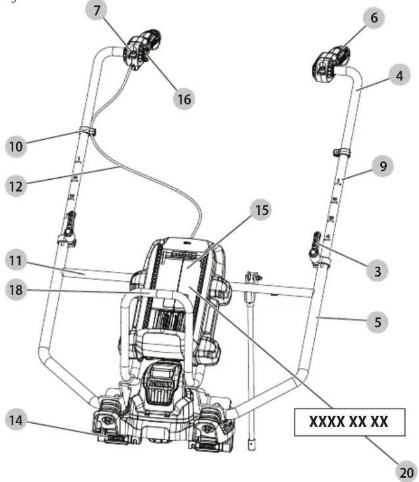
Date Code Position (Fig. A)
The production date code 20 consists of a 4-digit year followed by a 2-digit week and is extended by a 2-digit factory code.
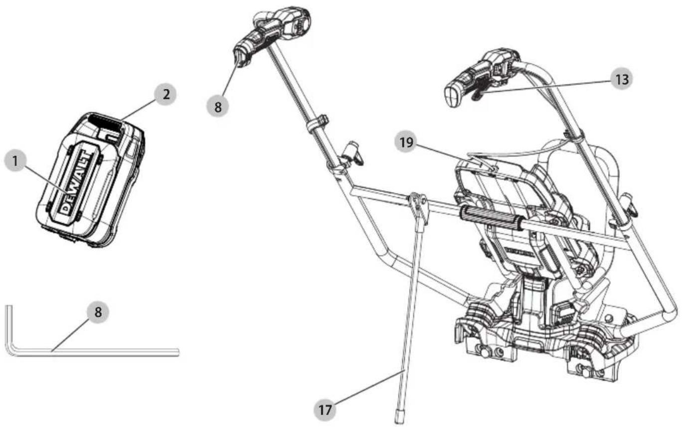
Description (Fig. A)
WARNING: Never modify the power tool or any part of it.
Damage or personal injury could result.
1 Battery pack
2 Battery release button
3 Height adjustment clamps
4 Handlebars
5 Frame
6 Handles
7 Handle angle/width adjustment screws
8 Hex wrench
9 Height markers
10 Cable clips
11 Frame crossbar
12 Throttle cable
13 Variable-speed trigger
14 Lock nut housing
15 Battery housing
16 Lock-on button
17 Kickstand
18 Front grip
19 Low battery charge indicator LED
20 Date code
Intended Use
This concrete power screed is designed for professional concrete leveling applications. The tool will accept the vast majority of L-shaped, triangular-style, and box-style beam designs from 1.2 m to 5 m in length.
DO NOT use under wet conditions or in the presence of flammable liquids or gases.
DO NOT let children come into contact with the tool. Supervision is required when inexperienced operators use this tool.
- Young children and the infirm. This appliance is not intended for use by young children or infirm persons without supervision.
- This product is not intended for use by persons (including children) suffering from diminished physical, sensory or mental abilities; lack of experience, knowledge or skills unless they are supervised by a person responsible for their safety. Children should never be left alone with this product.
ASSEMBLY AND ADJUSTMENTS
WARNING: To reduce the risk of serious personal injury, turn unit off and disconnect it from power source before making any adjustments or removing/installing attachments or accessories.
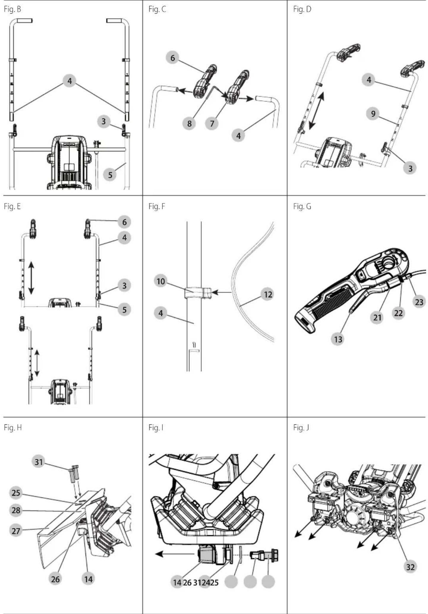
Attaching Handlebars (Fig. B)
- Loosen the height adjustment clamp 3 by turning it anticlockwise (when facing the clamp). Press the button in the centre of the clamp to freely rotate the clamp, allowing for an optimum tightening or slackening position. Release the button to lock the clamp handle into place.
- Slide the handlebar 4 into the frame 5, ensuring the height markers 9 are at equal positioning.
- Tighten clamps by rotating the clamp handle clockwise (when facing the clamp) to secure the handlebars.
- Repeat for other handlebar.
- To remove, loosen clamp and pull handlebar out.
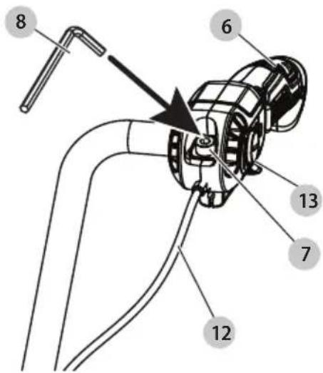
Attaching Handles (Fig. B, C)
Handles 6 can be attached no matter if the handlebars 4 are pointing in or out. They can also be switched from one handlebar to the other.
Attach handles after handlebars are attached.
- Slide handles onto handlebars so the handle angle/width adjustment screws 7 are facing up.
- Tighten the handle angle/width adjustment screws with the hex wrench 8 (found in the handle) to secure handles in desired location.
- To remove, loosen the handle angle/width adjustment screws and slide handles off.
Adjusting Handlebars
Adjusting Handle Height (Fig. D)
- Loosen the height adjustment clamps 3.
- Slide the handlebars 4 up or down to set at a comfortable height.
- Ensure both handles are set to the same height by lining them up to the same height marker 9.
- Close height adjustment clamps to secure into place.
Adjusting Handle Position (Fig. E)
The handlebars 4 can be switched to allow the handles 6 to be positioned inside or outside.
- Loosen the height adjustment clamps 3.
- Slide handlebars up and out of the frame 5.
- Switch handbars and reattach them as described in the
Attaching Handlebars section.
Cable Clips (Fig. F)
There are two cable clips 10 located on the handlebars 4 to hold the throttle cable 12 in place.
• To attach the cable, run it down the handlebar.
- Push it into the opening of the clips until it is fully inserted.
• To detach, simply pull the cable out of the clips.
NOTE: The cable clips can be moved around the concrete power screed handlebars to set them the way you desire.
Variable-Speed Trigger Adjustment (Fig. G, U)
Lever play increases with cable stretch and friction plate wear, requiring periodic adjustment.
- Open and close the variable-speed trigger 13 a few times to make sure it operates correctly.
-
Check the throttle cable 12 play and idle speed adjustment. Proper play is 8–13 mm.
-
Loosen the handle angle/width adjustment screws 7, so the handle 6 can be moved to the desired location.
- Once in place, tighten the handle angle/width adjustment screws with the hex wrench 8 to secure handles.
Trigger Gap (Fig. G)
When the variable-speed trigger 13 is slightly pressed, ensure the gap 21 at the end of the trigger is about 1-2 mm. If not, adjust the gap as described below.
- Loosen the lock nut 22.
- To increase the gap, rotate the cable adjuster 23 clockwise.
- To decrease the gap, rotate the cable adjuster counterclockwise.
nOTE: The distance between the cable adjuster and lock nut should be between 5 mm and 10 mm.
- Once the gap is appropriate, tighten the lock nut.
Attaching L-Shaped Beam (Fig. H)
- Lean the concrete power screed all the way on its front, so it rests on the front grip 18.
- Remove the M12x40 bolts 24 and M12 washers 25, but leave the plates 26.
- Position the L-shaped beam 27 (not supplied) on the back of the concrete power screed.
- Slide the M12x40 bolts through the M12 washers and beam holes 28 and into the concrete power screed.
- Tighten to 100 Nm.
- To remove beam, detach bolts and washers and pull beam away from the concrete power screed.
NOTE: When mounting the lock nut housing 14 and adaptors, torque is 100 Nm for M12 bolts and 20 Nm for M8 bolts.
Attaching Triangular Beam Adaptor (Fig. I–L)
To attach a triangular beam 29 (not supplied) to the concrete power screed, the triangular beam adaptor 30 must first be attached.
- Ensure the lock nut housing 14 is not attached by removing the M8 bolt 31, M12x40 bolts 24 and M12 washers 25. Leave the plate 26 in place.
- Remove the four M8x16 bolts and washers 32.
- Place the non-adjustable side of the adaptor 33 under the concrete power screed, facing the plate.
- Slide the M8x16 bolts and washers through the adaptor and into the concrete power screed.
NOTE: The M8 bolt may also be reinstalled to keep the bolt with the tool, but it is not required.
- Repeat for the other side.
Attaching Triangular Beam (Fig. J, L)
- Ensure the triangular beam adaptor 30 is attached.
- Slide the triangular beam 29 under the lip 34 of the non-adjustable side of the adaptor 33.
- Position the adjustable side of the adaptor 35 so it hugs the front of the triangular beam.
- Slide the M12x55 bolts 36 through the M12 washers 25 and the adaptor.
-
Tighten to 100 Nm.
-
To remove beam, loosen the adjustable side of the adaptor and pull the beam away.
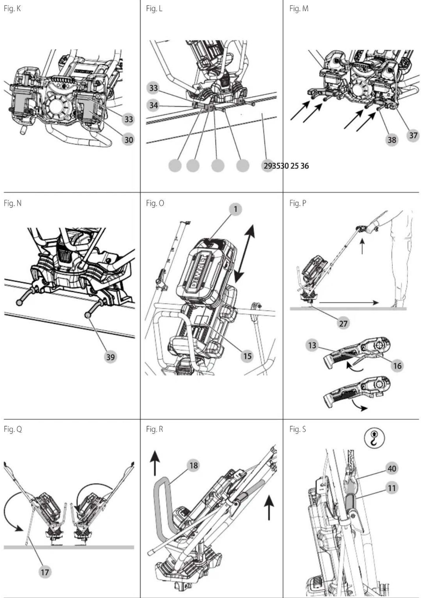
Attaching Adaptor to Enable Use With MULTIVIBE™\*\* Beams (Fig. J, M, N)
- Remove the four M8x16 bolts and washers 32.
- Place the adaptor for MULTIVIBE™ Beams 37 on the bottom of the concrete power screed.
- Slide the M8x45 bolts 38 through the adaptor and into the concrete power screed.
- Tighten to 20 Nm.
- Attach the beam by inserting the beam lever screws 39 through the front of the adaptor.
**MULTIVIBE™ is a brand owned by JLin Corporation.
OPERATION
WARNING: To reduce the risk of serious personal injury, turn unit off and remove the battery pack before making any adjustments or removing/installing attachments or accessories. An accidental start-up can cause injury.
WARNING: To reduce the risk of injury, wear protective gloves and boots when working with wet concrete.
WARNING: Before starting work, the surface to be worked on must be carefully inspected for any obstacles and concrete properties.
Installing and Removing the Battery Pack (Fig. 0)
WARNING: Ensure the tool is in the off position before inserting the battery pack.
NOTE: For best results, make sure your battery pack 1 is fully charged.
To Install the Battery Pack into the Tool
- Align the battery pack with the rails.
- Slide it in until the battery pack is firmly seated in the tool and ensure that you hear the lock snap into place.
To Remove the Battery Pack from the Tool
- Press the battery release button 2 and firmly pull the battery pack.
- Insert battery pack into the charger as described in the battery/charger manual.
Low Battery Charge Indicator LED (Fig. A)
When the battery charge becomes low, the low battery charge indicator LED 19 will flash every ten seconds. When the battery charge is depleted, the charge indicator LED will illuminate. This indicates that you need to charge or replace the battery before continuing to work.
WARNING: To avoid broken beams, do not let the concrete power screed run when not placed on soft, fresh concrete.
Use (Fig. P)
- Place the concrete power screed on wet concrete.
- Start concrete power screed by squeezing the variable-speed trigger 13.
- To increase speed, squeeze trigger further.
- To decrease speed, loosen your grip on the trigger.
- To maintain speed, press lock-on button 16. To unlock, squeeze trigger again.
- Move backward steadily, keeping the beam (27 or 29) level.
- Stop concrete power screed by releasing trigger.
How to Wet and Form-to-Form Screed (Fig. A)
Once the depth of the concrete has been determined and marked, place the concrete power screed where you plan to begin. Make sure the distance between the height markers 9 is shorter than your concrete power screed board.
Wet Screeding
- Spray the beam with concrete form oil or concrete release agent. This makes it easier to clean the product after operation because the concrete does not attach to the beam.
- Put the beam at the start of the first section of the concrete surface.
- Hold the handles tightly.
- Pull the variable-speed trigger 13 to increase or reduce the vibration.
AUTION: Too much vibration can bring excess moisture to the surface and too little vibration will likely prevent the concrete from being sufficiently levelled to the height markers.
- Walk slowly backward.
a. If wet screeding, lift the product until the rear edge of the beam is slightly lifted out of the concrete.
6. Once the desired section is complete, move to the next section, allowing 30 cm of overlap on the previous section of the concrete surface.
Form-to-Form Screeding
- Pour the concrete inside of the forms, slightly higher than the height of the forms themselves.
- Place the concrete power screed on top of the concrete with both ends of the blade contacting the form and begin pulling the throttle lever. The concrete power screed will then begin to vibrate.
- Walk backwards at a consistent rate.
- You can adjust the vibration via the variable-speed trigger to suit the slump level of the concrete.
- With the concrete in front of the blade, continue walking backwards to level and screed. The blade should remain flat on the form to ensure it is level and consolidated correctly. Concrete poured too high may cause the concrete to spill over the blade and should be raked during the process to avoid this. If this happens, the concrete power screed will become too heavy to pull, resulting in unevenness.
Kickstand (Fig. Q)
WARNING: To avoid injury and tipping when not in use, ensure the kickstand is all the way down and placed on stable ground before leaning the concrete power screed back.
The machine must not be running when it is parked on the kickstand.
- Before using the screed, flip the kickstand 17 up, ensuring it is all the way forward.
- When not using the concrete power screed, pull kickstand down all the way and lean concrete power screed back on it.
nOTE: Ensure kickstand is all the way down before leaning the concrete power screed back.
Transporting
WARNING: Heavy product. Get assistance if needed when transporting. The total weight of the machine, including battery and vibrating beam, could be above 25 Kg. Please check the sum of the weights and carry the assembled product with care by either using more persons or a suitable lifting device.
Transporting by Hand (Fig. R)
When moving concrete power screed, lift by front grip 18 together with the frame crossbar 11. Do not lift by handles or other concrete power screed parts. Doing so may cause damage.
When not in use, remove battery pack 1. Store concrete power screed in an indoor, dry, and locked-up place and out of reach of children.
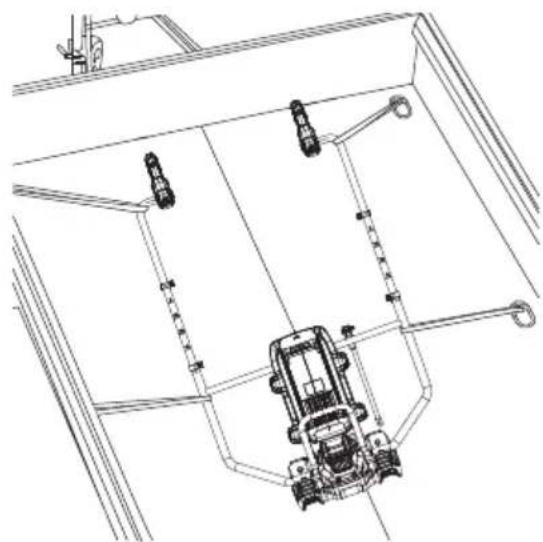
Transporting and Loading (Fig. S, T)
▲ANGER: Death hazard from suspended load! The machine is heavy. Improperly transporting the machine can cause it to fall and injure people.
- Ensure no persons will be endangered during transport or loading.
- Remove the vibrating beam from the concrete power screed before transportation or loading.
- Make sure all detachable parts are reliably secured and fixings are tightened.
• Always shut off the motor and remove the battery and beam when loading and transporting. - Make sure all detachable parts are reliably secured and fixings are tightened.
- Persons may not go near hanging loads or stand under hanging loads riding on a hanging load.
- Only use sufficiently strong and secure loading ramps when loading.
• The machine may swing when suspended. - Check the contact points (frame, lifting rings) before use for damage and wear. Immediately replace damaged parts.
- Secure the machine against rolling or slipping off and against tipping over.
- When loading, lashing down and lifting the machine always use the provided lifting points.
To transport the machine or lift it with a crane, do as follows:
- Always remove the battery before loading and transport.
- Make sure the motor has cooled.
- Hang the crane hook 40 from the frame crossbar 11.
- Load the machine onto the transport vehicle.
- Remove the crane hook from the designated lifting point.
- Secure the machine to the rigid metal frame of the vehicle with straps and load it correctly.
- At the destination, loosen the transport straps.
- Hang the crane hooks into the designated lifting point.
- Lift the machine with a crane and unload it.
- Place the machine on a level floor and prepare it for operation.
Loading (Fig. S)
WARNING:
- Persons may not go near hanging loads or stand under hanging loads riding on a hanging load.
- Only use sufficiently strong and secure lifting accessory like chain or rope.
• The machine may swing when suspended. -
Check the rigid metal frame before lifting for damage and wear. Immediately replace damaged parts before lifting.
-
For lifting the machine with a crane, hang the crane hook 40 from the frame crossbar 11.
- Lift the machine carefully until it is in a stable position.
Tying the Machine Down (Fig. T)
WARNING: Secure the machine against rolling, slipping, and tipping over.
• After loading the concrete power screed on the vehicle, lay the machine down on its back so it rests on the handles, and tie it down at points along the frame.
- Strong metal parts can be used for tying. Do not use the strap where the throttle cable or plastic parts are stressed.
- When tightening the straps, make sure the metal frame does not warp.
- It is in the responsibility of the transporter to choose sufficient methods for securing the product.
- Make sure no other objects on the loading area can damage the machine during transportation.
Storage
Preparation for Storage
If the machine is to be shut down for an extended time (longer than six weeks), it should be placed stably on a pallet on a firm, even surface.
- The storage area should be dry and protected.
• The ambient temperature should be between 0 °C and 45 °C.
• Before storing the machine: - Clean it thoroughly.
- Check for leaks and damage, and fix any problems.
- Cover it with a protective tarpaulin.
Returning the Machine to Service
Before returning the machine to service, check the machine for:
- leaks.
- any other damage.
Check all screws, nuts, and bolts for firm seating and tighten them if needed.
MAINTENANCE
Your power tool has been designed to operate over a long period of time with a minimum of maintenance. Continuous satisfactory operation depends upon proper tool care and regular cleaning.
WARNING: To reduce the risk of serious personal injury, turn tool off and disconnect battery pack before making any adjustments or removing/installing attachments or
accessories. An accidental start-up can cause injury.
The charger and battery pack are not serviceable.
Please refer to the back page of this manual for service centre contact information, or visit www.2helpU.com.
General Maintenance Information
- Observe the safety regulations!
- Please refer to the back page of this manual for service centre contact information, or visit www.2helpu.com.
- Only qualified, authorised persons may carry out repairs.
- In the event of faults, refer to the Operation and
Maintenance instructions for correct operation and maintenance.
- If the fault can not be located, refer repairs to an authorised DEWALT service centre.
- Concrete power screeds must be tested for safety depending on the operating conditions required, at least once a year by an authorised DEWALT service centre.
- If the machine should break down, hang a warning sign on the handle.
Optional Accessories
WARNING: Since tools and accessories, other than those offered by DEWALT, have not been tested with this product, use of such tools and accessories with this battery could be hazardous. To reduce the risk of injury, only DEWALT-recommended tools and accessories should be used with this battery. Consult your dealer for further information on the appropriate accessories. Industrially standardised vibrating beams can be attached.
Lubrication
Your power tool requires no additional lubrication.
Cleaning
WARNING: Electrical shock and mechanical hazard. Remove the battery before cleaning.
WARNING: To ensure safe and efficient operation, always keep the electrical appliance and the ventilation slots clean.
WARNING: Never use solvents or other harsh chemicals for cleaning the non-metallic parts of the tool. These chemicals may weaken the materials used in these parts. Use a cloth dampened only with water and mild soap. Never let any liquid get inside the tool; never immerse any part of the tool into a liquid.
WARNING: Never clean the machine with the motor running.
WARNING: DO NOT allow water to splash onto the battery rail and terminal block area. Wipe all battery interface components dry.
WARNING: When using a water hose, do not aim the water towards electrical parts and cover these in advance.
WARNING: Risk of fire and explosion caused by inflammable substances. For cleaning, do not use any flammable or aggressive materials.
NOTICE: Property damage hazard to the machine from high pressure water.
Ventilation slots can be cleaned using a dry, soft non-metallic brush and/or a suitable vacuum cleaner. Do not use water or any cleaning solutions. Wear approved eye protection and an approved dust mask.
IMPORTanT: Clean the machine daily.
- Remove the battery.
- Install the transport cap on the battery.
- Protect the motor well from water.
- Wipe the machine dry with a clean, dry cloth.
- Dry any damp spots on the machine that may have occurred during cleaning.
- After cleaning, check the cables and wires, screws, nuts, and bolts for firm seating, loose connections, chafe marks and other damage and for contamination of the batteryterminals.
Eliminate any problems immediately.
Battery Cleaning Instructions
WARNING: Dirt and grease may be removed from the exterior of the battery using a cloth or soft non-metallic brush. Do not use water or any cleaning solutions. Never let any liquid get inside the battery; never immerse any part of the battery into a liquid.
Protecting the Environment


Products/batteries are recyclable, but if marked with the crossed-out bin, they must not be disposed of with normal household waste.
Run the batteries down completely and separate them, and separate any light sources from the product if possible. It is the user's responsibility to delete personal data from the product. Then take the waste to an official waste collection center or a participating retailer who will often accept it free of charge. Packaging should be discarded based on the marked material code. Operating and safety instructions should only be discarded once the applicable product is no longer in use. Please check with your local community/municipality for waste management guidance. For further information, visit www.2helpU.com and scan the above QR code.
REGLA ELÉCTRICA PARA HORMIGÓN DEWALT POWERSHIFT™
DCPS330

Vice-President Engineering, PTE-Europa
WAARSCHUWING: Lees alle
BEWAAR ALLE WAARSCHUWINGEN EN INSTRUCTIES ALS TOEKOMSTIG REFERENTIEMATERIAAL
DEWALT POWERSHIFT™ BETONGRETTHOLT
DCPS330

DEWALT POWERSHIFT® Betongrettholt DCPS330
1 DEWALT POWERSHIFT Betongavretter
1Trekantetbjelkeadapter
1 Adapter Multivibe ^TM bjelke**
1Bruksanvisning
Forberedelse for lagring
Montar as pegas (Fig. B, C)
DEWALT POWERSHIFT® betongsloda DCPS330
Vice-President Engineering, PTE-Europa
DEWALT, Richard-Klinger- Straße 11,
65510, Idstein, Tyskland
31.12.2024

1 DEWALT POWERSHIFT betongsloda
1 triangulärbalkadapter
1 adapter Multivibe TM-balk**
1bruksanvisning