PLT-9 - Pan MSW - Free user manual and instructions
Find the device manual for free PLT-9 MSW in PDF.

User questions about PLT-9 MSW
0 question about this device. Answer the ones you know or ask your own.
Ask a new question about this device
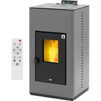
Download the instructions for your Pan in PDF format for free! Find your manual PLT-9 - MSW and take your electronic device back in hand. On this page are published all the documents necessary for the use of your device. PLT-9 by MSW.
USER MANUAL PLT-9 MSW
EN Manufacturer Address
PL Adres producenta
CZ Adresa výrobce
A - 0,5 m
B - Abstand >2 m
C - Abstand <2 m
D - 0,5 m
A - mindestens 2,6 m
B - Abstand >1,5 m
C - Abstand <1,5 m
natural_image
Three-panel image showing hands holding black wires and a close-up of a small object with red circle highlighting (no text or symbols)natural_image
Two-panel image showing hands using a black electronic device to install a cable or cable clip, no visible text or symbols.natural_image
Close-up of a black plastic container with a green checkmark arrow pointing to it (no text or symbols visible)
natural_image
Black rectangular object with a hole, placed on a textured surface with a red 'X' mark in the corner (no text or symbols on the object itself)natural_image
Close-up of a hand inserting a black plastic bag into a black plastic container (no text or symbols visible)natural_image
Person applying a black rubber hose to a red floor, with a vacuum cleaner visible nearby (no text or symbols)This User Manual has been translated for your convenience using machine translation. Reasonable efforts have been made to provide an accurate translation; however, no automated translation is perfect nor is it intended to replace human translators. The official User Manual is the English version. Any discrepancies or differences created in the translation are not binding and have no legal effect for compliance or enforcement purposes. If any questions arise related to the accuracy of the information contained in the User Manual, please refer to the English version of those contents which is the official version.
Technical data
| Parameter description | Parameter value | |||
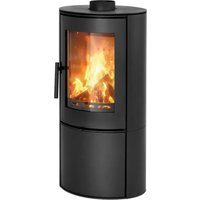
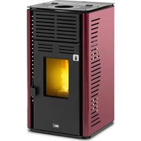
| Product name | Pellet stove | |||
| Model | MSW-PLT-6 | MSW-PLT-9 | MSW-PLT-13 | |
| Supply voltage [V~] / Frequency [Hz] | 230/50 | |||
| Rated input power [W] | 47-380 | |||
| Safety class | I | |||
| IP class | IPX0 | |||
| Dimensions [Width x Depth x Height; mm] | 440 x 490 x 790 | 500 x 428 x 910 | 610 x 500 x 940 | |
| Net/gross weight [kg] | 60/70 | 78/88 | 115/130 | |
| Nominal and reduced thermal power [kW] | Maximum 6 9 | 13 | ||
| Minimal 2.5 3 | 3 | |||
| Energy efficiency [%] | Minimal | 90 | ||
| Maximum | 80 | |||
| Ash content | 0,12% | |||
| Auxiliary electricity consumption [W] | 47-60 | |||
| Fuel type | wood pellets | |||
| Remote control battery | AAA LR03 1.5V (x2) | |||
| Inlet pipe diameter [mm] | 50 | |||
| Outlet pipe diameter [mm] | 80 | |||
| Minimum safe distance of a side of the device from flammable materials [mm]: | Right = 1200Back = 250Left = 1200 | |||
| Tank capacity [kg] | 10 | 16 | 25 | |
| Pellet consumption [kg/h] | 0.5-1.4 | 0.6-1.6 | 0.6-3.6 | |
| Efficiency [%] | 90 | |||
| Heating area [≤m2] | 60 | 90 | 130 | |
| Automatic operation time [h] | 7-20 | 10-27 | 7-36 | |
1. General Description
This manual is intended to assist you for safe and reliable use. The product is designed and manufactured strictly according to technical specifications using the latest technology and components and maintaining the highest quality standards.
CAREFULLY READ AND UNDERSTAND THIS MANUAL BEFORE STARTING THE WORK.
To ensure long and reliable operation of the device, make sure to operate and maintain it properly in accordance with the guidelines in this instruction manual. The technical data and specifications in this manual are up-to-date. The manufacturer reserves the right to make changes in order to improve the quality. Taking the technical progress and the possibility of reducing noise into account, the unit is designed and built in such a way so that risks resulting from noise emissions are reduced to the lowest possible level.
Explanation of symbols
 | The product complies with applicable safety standards. |
 | Read the manual before use. |
 | Recyclable product. |
 | CAUTION! or WARNING! or REMEMBER! describing a situation (general warning sign). |
 | Wear protective gloves. |
 | Caution! Hot surface can cause burns!(the exhaust pipe can heat up to 160°C during operation!) |
 | For indoor use only. |
 | Do not cover the unit with any materials or objects. |

CAUTION! The figures in this manual are illustrative only and may vary in some details from the actual appearance of the product.
2. Safety of use
CAUTION! Read all safety warnings and instructions. Failure to follow the warnings and instructions may result in electric shock, fire and/or serious injury or death.
The term "device" or "product" in the warnings and in the description of the manual refers to:
Pellet Stove.
2.1. Electrical safety
a) The plug of this device must fit into the outlet. Do not modify the plug in any way. Original plugs and matching outlets reduce the risk of electric shock.
b) Do not touch the device with wet or damp hands.
c) Do not use the cord in an unintended manner. Never use it to carry the device or to pull the plug out of the socket. Keep the cord away from heat sources, oil, sharp edges or moving parts. Damaged or tangled cords increase the risk of electric shock.
d) Do not use the unit if the power cord is damaged or shows signs of wear. A damaged power cord should be replaced by a qualified electrician or the manufacturer's service department.
e) To avoid electric shock, do not immerse the cable, plug, or the device itself in water or other liquid. Do not use the appliance on wet surfaces.
f) CAUTION – DANGER TO LIFE! When cleaning or using the appliance, never immerse it in water or other liquids.
g) Do not use the appliance in rooms with very high humidity / in the immediate vicinity of water tanks!
h) Do not allow the machine to get wet. Risk of electric shock!
2.2. Safety in the workplace
a) Keep the work area tidy and well lit. Disorder or poor lighting can lead to accidents. Be foresighted, watch what you are doing and use common sense when using the unit.
b) Do not use the unit in an explosive area, for example in the presence of flammable liquids, gases or dust. The unit produces sparks that can ignite dust or fumes.
c) If you find any damage or irregularities in the operation of the unit, immediately turn it off and report it to an authorized person.
d) If you have any doubts as to whether the product is working properly or if it is damaged, contact the manufacturer's service department.
e) Repairs to the device may only be carried out by the manufacturer's service. Do not attempt to repair the product on your own!
f) In case of open flames or fire, use only dry powder or snow (CO2) fire extinguishers to extinguish the live equipment.
g) No children or unauthorized persons are allowed in the work area. (Inattention may result in loss of control of the unit.)
h) Use the unit in a well-ventilated area.
i) When starting to operate the unit, gradually increase the air supply to the unit to make sure it is working properly. If you notice that the unit is not working properly, immediately disconnect it from the compressed air supply and contact the manufacturer's service department.
j) In the event of danger to life or limb, accident or breakdown, stop the unit with the EMERGENCY STOP button!
k) Check the condition of the safety stickers regularly. Replace them if they are illegible.
I) Keep these instructions for use for future reference. If the product is to be handed over to a third party, hand it over with this user manual.
m) Keep packaging components and small installation parts out of the reach of children.
n) Keep the device away from children and animals.
o) When using this product together with other devices, also follow the other instructions for use.
p) Install the product in accordance with local, national and state laws and regulations. In addition, the installation must be performed by authorized personnel professionally trained for this type of work.

Remember! Keep children and other bystanders safe while operating the equipment.
2.3. Personal safety
a) Do not operate this device if you are tired, ill or under the influence of alcohol, drugs or medication that could impair your ability to operate the device.
b) The device is not intended to be used by persons (including children) with reduced mental, sensory or intellectual functions or persons who lack experience and/or knowledge unless they are supervised or have been instructed by a person responsible for their safety on how to operate the device.
c) The unit may be operated by persons who are physically fit, capable of operating it and appropriately trained, and who have read this instruction manual and have been trained in occupational safety and health.
d) Use caution and common sense when operating this unit. A moment's inattention during operation may result in serious personal injury.
e) Use personal protective equipment as required when operating the unit as specified in Section 1 of the explanation of symbols. The use of appropriate, approved personal protective equipment reduces the risk of injury.
f) The product is not a toy. Children should be watched to ensure that they do not play with the appliance.
2.4. Safe use of the device
a) Do not use the device if the ON/OFF switch does not function properly (does not turn on and off). Units that cannot be controlled by the switch are unsafe, cannot operate, and must be repaired.
b) Disconnect the device from the power supply before adjusting, cleaning, or servicing. This precaution reduces the risk of accidental start-up.
c) Keep the unit in good working condition. Check before each use for general damage or damage to moving parts (cracks in parts and components or any other condition that may affect the safe operation of the device). If damaged, have the device repaired before use.
d) Keep the product out of the reach of children.
e) Repairs and maintenance should be carried out by qualified personnel using only original spare parts. This will ensure the safety of use.
f) To ensure the designed operational integrity of the device, do not remove factory-installed covers or loosen screws.
g) Avoid situations in which the device stops under heavy loads during operation. This can cause overheating of the drive elements and consequent damage to the equipment.
h) Do not touch any moving parts or accessories unless the device is unplugged.
i) Clean the device regularly to prevent permanent dirt build-up.
j) Use wood pellets to power the unit. It is forbidden to use other fuels or waste.
k) The product is not a toy. Cleaning and maintenance must not be performed by children without adult supervision.
I) Do not start up an empty unit.
m) Do not tamper with the device to alter its performance or design.
n) Do not overload the device.
o) Do not block the ventilation openings of the unit!
p) Do not put or dry linen on the product. Any dryers and similar devices should be kept at a suitable distance from the product.
q) Incorrect use of the product or improperly performed maintenance may pose a serious risk of explosion in the combustion chamber!
r) Do not operate the product with the door open or with the glass broken. If the ignition system is damaged, ignition with flammable materials must not be forced.
s) Do not touch the front of the unit during operation - risk of burns!

CAUTION! Although the product has been designed to be safe and has adequate safeguards and despite the additional safety features provided to the user, there is still a slight risk of accident or injury when handling the product. Caution and common sense are advised when using the product.

WARNING: It is forbidden to use this product in cars, caravans, truck, tents etc.
WARNING: It is forbidden to use this product in cars, caravans, truck, tents etc.

ATTENTION! If installation has not been carried out in accordance with the procedures indicated, in the event of failure power supply, it may happen that some of the exhaust gases penetrate into the room. In some cases it may be necessary to install a UPS unit to maintain the draft.

Expondo shall not be held liable in any way whatsoever for damage to persons or objects resulting from non-compliance with the rules described in the aforementioned points and for products not installed in accordance with the standards.
3. Instructions for use
The device is designed to generate heat for heating buildings and water by burning pellets. It is suitable for permanent installation in buildings, however, it is not suitable for use in prefabricated houses.
IMPORTANT: the product is designed to burn only wood pellets, do not use other types of pellets and wood. We recommend using pellets that meet (or exceed) the following standards:
| Moisture content (after combustion) according to CEN/TS 14774-1 and ISO 687 | ≤12% |
| Ash content (after combustion) according to ISO 1171 | ≤0.7% (without bark)≤2.0% (with bark) |
| Volatile matter content (dry, ashless base) according to ISO 562 | 80% to 88% |
| Hydrogen content (after combustion) according to ISO 609 | 5.0% to 6.5% |
| Carbon content (after combustion) according to ISO 609 | 40% to 50% |
| Sulfur content (after combustion) according to ISO 351 and ISO 334 | ≤0.1% |
| Calorific value according to ISO 1928 | 16,900 KJ/kg to 19,500 KJ/kg |
| Diameter | 6 mm |
| Length | ≤40 mm |
Use of moist and/or contaminated pellets (e.g. high salt or sand content) will worsen the operation and performance of the unit. Also, improper storage of
pellets affects their efficiency, especially when they are not kept in a dry room and/or their structure is damaged.
The user is responsible for any damage resulting from misuse.
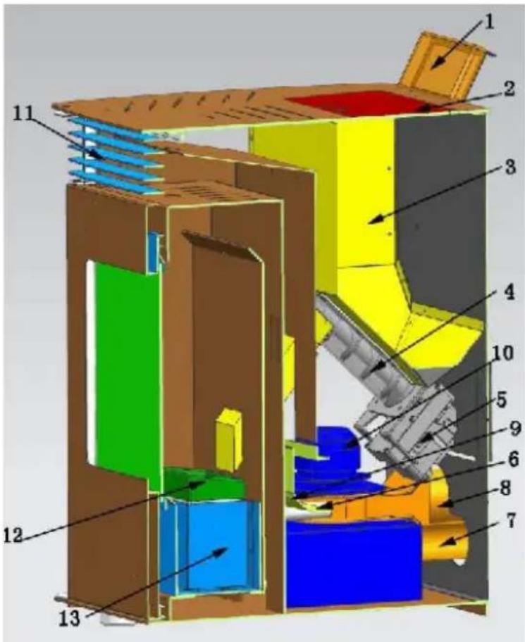
3.1. Product overview
MSW-PLT-9 / MSW-PLT-13:
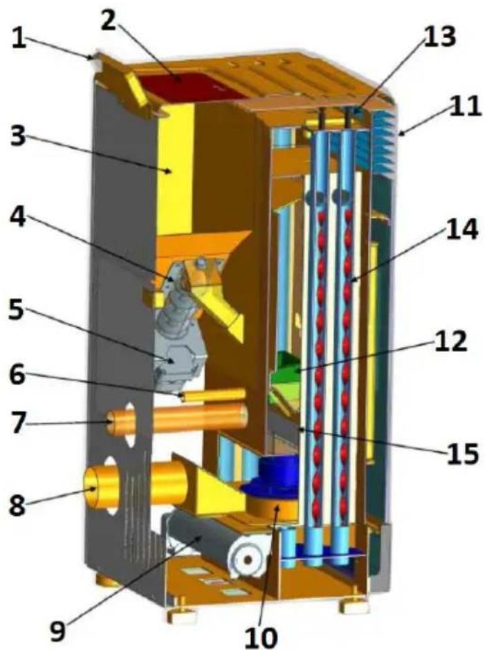
- Control panel
- Hopper lid
- Hopper
- Worm
- Worm motor
- Igniter
- Air inlet pipe
- Exhaust pipe (to the chimney)
- Blower fan
- Exhaust fan
- Heat outlet
- Hearth
- Knob
EN
- Spiral blades
- Ash container
- ON/OFF switch (on the back of the housing next to the power cord socket - not visible in the picture)
MSW-PLT-6:
- Control panel
- Hopper lid
- Hopper
- Worm
- Worm motor
- Igniter
- Air inlet pipe
- Exhaust pipe (to the chimney)
- Blower fan
- Exhaust fan
- Heat outlet
- Hearth
-
Ash container
-
ON/OFF switch (on the back of the housing next to the power cord socket - not visible in the picture)
3.2. Preparation for operation
POSITIONING OF THE UNIT
The ambient temperature must not exceed 40^ C and ambient humidity should not exceed 85%. Place the unit in a way that ensures good air circulation. Maintain the minimum recommended distance from each wall of the unit. Keep the device away from any flammable materials or objects. Always operate the unit on a level, stable, clean, fireproof and dry surface and out of the reach of children and persons of impaired mental, sensory and intellectual functions. Place the unit in such a way that the mains plug can be reached at any time. Ensure that the power supply to the unit corresponds to that specified on the identification plate!
If it is not possible to place the appliance on a fireproof surface, place it on a non-flammable, heat-resistant pad with a minimum thickness of 15 mm and extending beyond the outline of the stove (see the technical data table) plus an additional 150 mm from the front.
ASSEMBLY OF THE DEVICE
IMPORTANT: Installation, electrical and water connection as well as functional testing and maintenance must be performed only by an authorized, qualified person. Install the product in accordance with local, national and state laws and regulations.
Chimney/ventilation:
Minimum required insulated steel - T400 (or higher) - resistant to soot ignition. The chimney should have a single, mandatory inspection hatch ("a" in the picture below)/inspection flap (b), and the entire installation should be in accordance with EN1856-1 and -2.
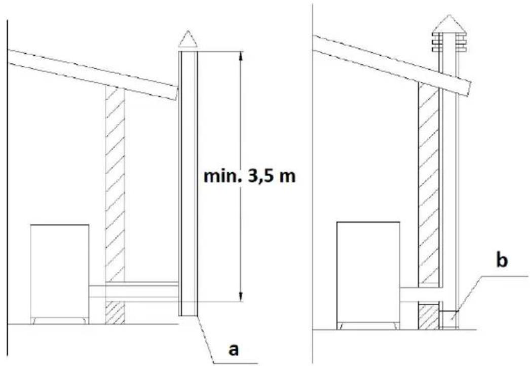
The chimney installation should be airtight, vertical, without any narrowings, made of a smoke-impermeable material, thermally insulated (to avoid condensation or cooling the smoke) and resistant to normal mechanical stress coming with time - recommended AISI 304 chimney steel with a round section. The installation should be separated from flammable or combustible materials by an air gap or adequately insulated with materials - see standard EN1443. The chimney opening must be in the same room as the unit or at most in an adjacent room. Underneath must be a soot and condensate collection chamber - accessible through a waterproof, metal hatch.
- Flat roof
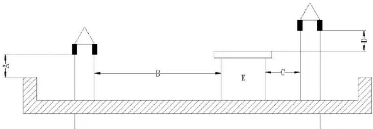
A - 0.5 m
B - distance >2 m
C - distance <2 m
D - 0.5 m
E - tech volume.
- Roof with a slope of 15 °
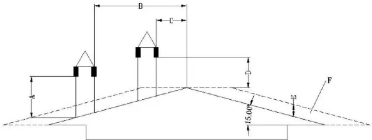
A - min. 1 m
B - distance >1.85 m
B - distance <1.85 m
D - 0.5 m above the highest point of the roof
E - 0.5 m
F - drainage area
- Roof with a slope of 30 °
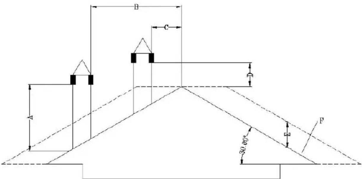
A - min. 1.3 m
B - distance >1.5 m
C - distance <1.5 m
D - 0.5 m above the highest point of the roof
E - 0.8 m
F - drainage area
- Roof with a slope of 60 °
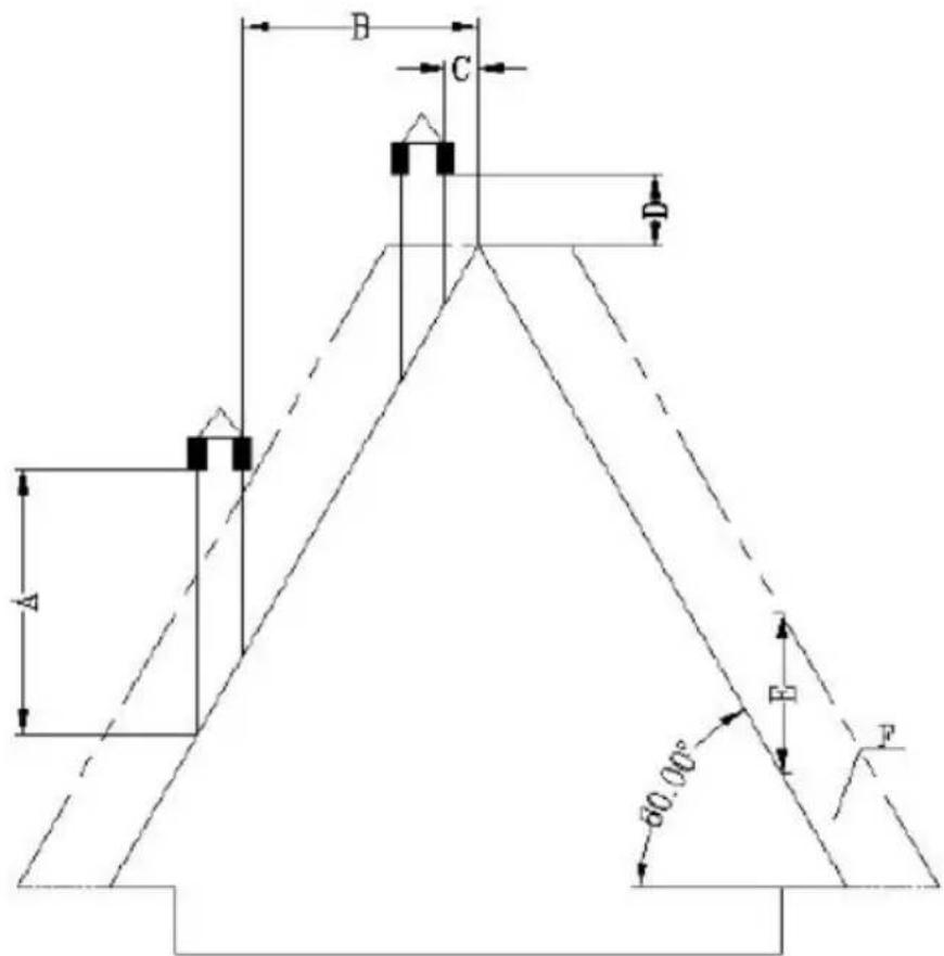
A - min. 2.6 m
B - distance >1.5 m
C - distance <1.5 m
D - 0.5 m above the highest point of the roof
E - 0.8 m
F - drainage area
• Roof with a slope of 45 degrees
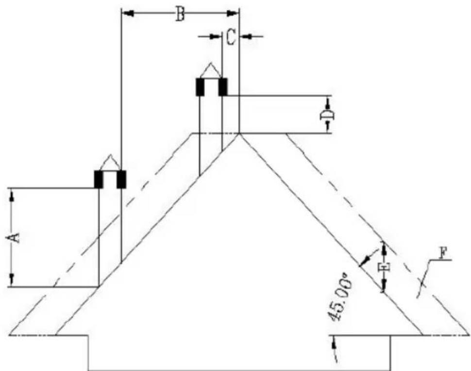
A - min. 2 m
B - distance >1.3 m
C - distance <1.3 m
D - 0.5 m above the highest point of the roof
E - 2.1 m
F - drainage area
Requirements for the end of the chimney:
- Do not route the chimney to end in closed or roofed spaces (e.g. carport, garage, attic, mezzanine, under the sun deck, porch, staircase, vestibule, etc.)
- The surface of the exhaust pipe can reach really high temperatures (up to 160^ C), so it should have a resistant to high temperatures, non-flammable warning against the risk of severe burns or properly insulated with non-flammable material.
- The end of the ventilation chimney must be higher than the air inlet pipe. If the smoke is discharged directly through the wall, it is recommended that the vertical chimney pipe be at least 1.5 m long for outdoor installation. This will prevent the ingress of smoke and its odor back into the building when the power is turned off, and avoiding hot vapors that can ignite the wood and burn the user at the same time.
- The end of the chimney should not be lower than 1.2 m, the horizontal distance not less than 1.2 m, and the vertical distance not less than 0.3 m from the doors, windows and the building's gravity/ventilation inlets.
- The distance of the bottom of the chimney should be at least 304 mm from the ground and more than 2 m from any public walkway.
- The end of the chimney should be at least 0.6 m away from flammable materials such as bushes, plants, grasses, fences, building overhangs and adjacent buildings.
- A pipe type "PL" or "L" must be used for smoke ventilation. Use an approved wall rosette or ceiling firewall in the place where the chimney passes through the flammable ceiling wall.
- All chimney connections should fit tightly together, be twisted together (if the pipes do not have a locking system) and sealed. The longer the pipe connecting to the chimney's exhaust pipe and the more elbows it has, the greater the resistance to the flow of smoke.
Installation in a mobile home (Dutch):
- The air inlet to the outside of the mobile home should always be well below the end of the chimney.
- The tip of the chimney requires a cover (canopy) to protect the house from rain and pests.
- The stove must be securely attached to the floor with screws.
- The stove must be grounded with an 8 mm or larger copper wire.
Overvoltage protection:
The use of an overvoltage protector is recommended to protect the electrical components of the stove from damage due to voltage fluctuations in the electrical system.
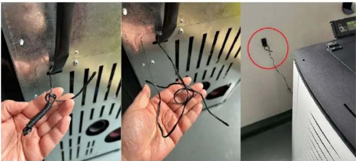
Temperature protection:
It applies only to products manufactured before 2023. Products manufactured after 2023 have a factory-installed ambient temperature sensor in a location determined by the manufacturer.
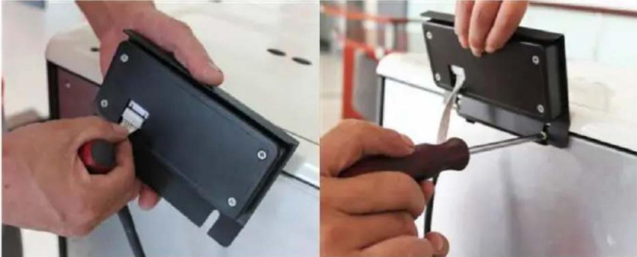
For the proper operation of the stove, it is necessary to install a temperature sensor (low voltage thermostat) in the room in which the stove will work to measure the ambient temperature. The sensor/thermostat is connected to the back of the stove (see pictures below) - its cord should be unrolled and preferably attached to the wall of the room in which the stove is located, but away from the exhaust pipe and cold objects that could interfere with its proper operation.
natural_image
Three-panel photo showing hands holding wire and wires in a lab setting, one with a red circle highlighting a device (no visible text or symbols)Installation of the control panel:
Attach the control panel with the display to the back of the stove from above withthe screws. Then connect it with the power plug - see the pictures below:
natural_image
Two-panel image showing hands using a black electronic device to install a black plastic clip or bracket (no text or symbols visible)3.3. Working with the device
3.3.1 Control panel / remote control
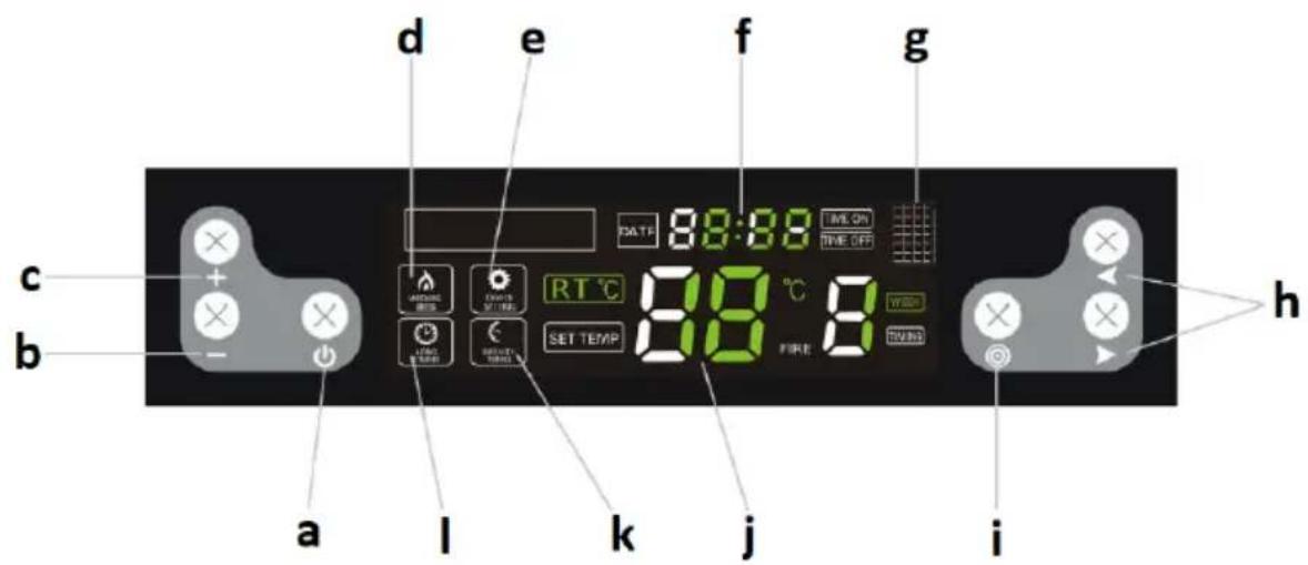
a. Device on/off button
b. Parameter decrease button
c. Parameter increase button
d. Operation mode indicator
e. Setting mode indicator
f. Clock
g. Infrared port (for remote control)
h. Function selection / switching buttons
i. Settings selection button
j. Temperature
k. Time slot indicator
I. Long time indicator
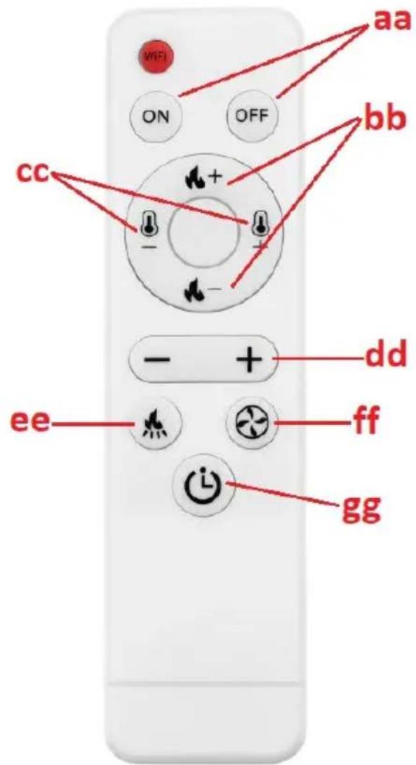
bb. Buttons for setting the ignition level
cc. Temperature level setting buttons
dd. Value increase/decrease button for a given parameter
ee. Button to set the operating frequency of the pellet feeder
ff. Button to set the speed of the exhaust fan
hg. Button for simplified changes in timer mode
3.3.2 Before starting up for the first time
IMPORTANT: the stove may give off an unpleasant odor when it is first used - the paint inside will burn out. This is normal and is not a product defect - the unpleasant odor should pass over time.
- Put the pellets into the furnace by pouring them in (it is not necessary to fill the hopper completely).
- Set the red power switch (14) to the ON ("I") position - it should light up, which means that the stove has power and started working.
- After start-up, the stove system will go into the self-diagnosis procedure and if successful, the device is ready for operation.
3.3.3 Starting and working
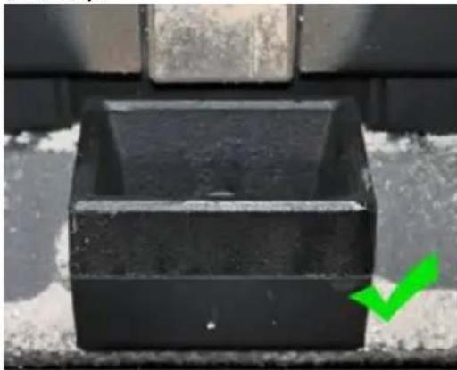
IMPORTANT: before putting it into operation, make sure that the hearth (12) is filled with pellets and that the ash container (13 or 15 depending on the model) is correctly positioned (see the pictures below):
natural_image
Close-up of a black plastic container with a green checkmark arrow pointing to it (no text or symbols visible)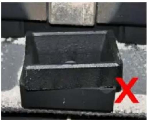
natural_image
Black rectangular object with a horizontal line and a red 'X' mark, placed on a textured surface (no text or symbols visible)Before ignition, the remains of unburned pellets must be removed from the hearth.
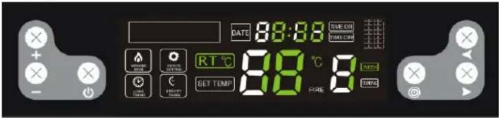
a) Switching on/off
To start the stove, put the power switch (14 or 16) in the "I" position and press the on/off button (a). The device will start and enter the automatic ignition mode, and the information on the display will look like this:

Similarly, use the same button (a) to turn off the stove, and the display will be as follows:

When the stove enters the automatic ash cleaning mode, the display will be as follows:
NOTE: after turning off the stove, the fire will continue to burn until the pellets in the hearth are completely burnt out. During this time, both fans will run - the airflow and the exhaust fan. The combustion time is approx. 15 minutes.
b) Setting the timer to turn on/off
With the stove off, press and hold the on/off button (a) to set the timer for 12 hours, i.e. the stove will turn on automatically after 12 hours. When the controls are blinking:

Use the parameter increase/decrease buttons (b/c) and the switching button (h) to adjust the time until the stove is switched on.

In the same way, during the operation of the stove, you can set the time until it is turned off, i.e. by pressing and holding the on/off button (a). When they blink:

Use the parameter increase/decrease (b/c) and toggle (h) buttons to adjust the time until it is turned off.
After setting the on/off time, the timer on the display will show every 5 seconds how much time is left until the stove starts/stops.
c) Weekly timer setting
It is possible to individually program the time of switching on and off the stove for each day of the week - with the option of 2 rounds of switching on/off each day. To do this, press the settings selection button (i) 4 times. Press the function/switching buttons (h) to select the hours and minutes and the day, and adjust the values with the decrease/increase buttons (b/c). After setting it for a given day, you can set a second on/off on the same day by pressing both function/switching buttons (h) at the same time. You can also set one and the same on/off time for each day of the week.
NOTE: the function to switch the stove on and off twice a day is only available for models produced after 2022.
IMPORTANT: before setting the weekly time schedule, do not set a single on/off time as the single setting has priority and then the weekly schedule will not work.
To cancel the weekly timer, press the settings button (i) 4 times, then use the function/switching buttons (h) to select the setting you want to delete and press the value decrease button (-) until the clock display (f) shows value:
Then you can select another time with the toggle buttons (h) to delete and repeat the steps described above. Pressing and holding the settings button returns to the setting change:
After deleting the entire weekly timer, the indicator will turn off on the display:

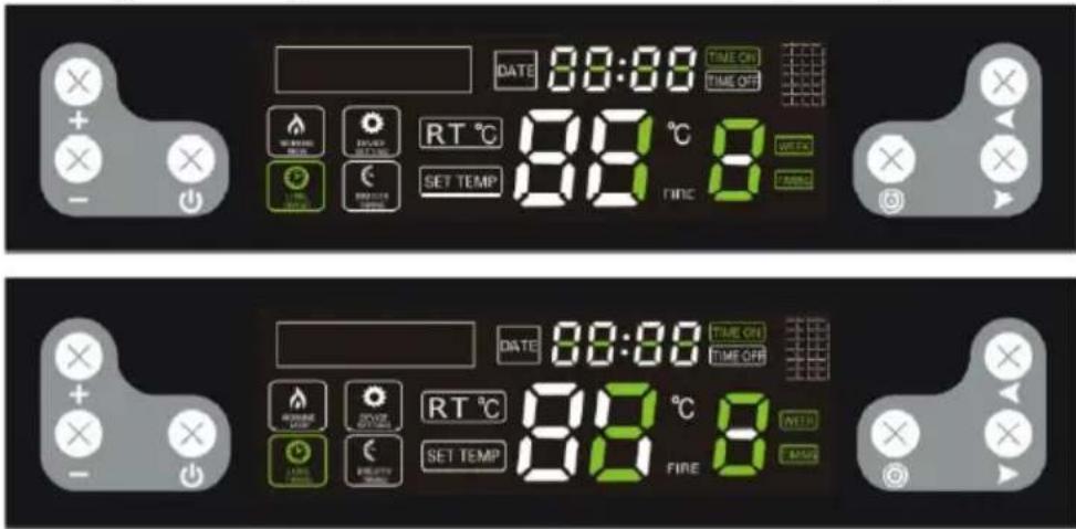
d) Temperature setting
Press the settings button (i) and if the light:

starts blinking, set the temperature in the range of 10-35 °C. If the temperature in the heated room reaches the set value, the device will automatically switch to the lowest program P1 - "economy".

IMPORTANT: if the temperature in the hopper reaches or exceeds 90^ C. The stove will also turn off when the temperature inside it reaches 700^ C.
e) Setting the fire and the blower
Pressing the settings button (i) twice will activate the fire setting option. If the following controls:

flash, one of the following programs can be selected - P0, P1, P2, P3, P4. "P0" is an automatic program, i.e. the stove automatically adjusts the fire level to the set temperature. "P1" is an economic program - when the set temperature in the heated room is reached, the stove will automatically switch to the "P1" economy program.

IMPORTANT: in the event that the fire darkens and smoke is coming out of the chimney, the airflow in the combustion chamber should be accelerated.
f) Setting the operation of the pellet feeder
Pressing the settings change button (i) 3 times will activate the option of setting the operating frequency of the pellet feeder. If the following controls:

are blinking, you can set the operation of the pellet feeder depending on the quality of the pellets used. The adjustment is in the 1-5 range. The "3" level is the factory setting, while the value decrease/increase (b/c) buttons can be used to change the frequency of the feeder, e.g. if you select level 2, it means that the operating frequency will be 10% higher than the factory
setting for each of the programs, i.e. pellets will be fed more frequently and the opposite will happen for higher values.

IMPORTANT: if the temperature inside the stove reaches 700^ C, the pellet feeder will stop until the temperature drops to 650^ C.
g) Clock setting
Pressing the button 5 times allows you to go to the clock setting. When the controls:

are blinking, set the current day and time with the function/switching buttons (h).
3.3.4 Error lights
Disturbances in the proper operation of the stove may result in displaying one of the error codes on the screen:
| Error code | Meaning | Possible cause |
"E1" | Room temperature sensor error. | Damaged temperature sensor circuit on the motherboard.The temperature sensor itself is defective.Cold solder. |
"E2" | Thermoelectric sensor (thermocouple) error. | Deposition of soot on the sensor affecting its operation.Thermocouple defective. |
"E3" | Smoke temperature sensor error, i.e. the sensor sees the temperature as too low and there is no ignition in the hearth or the ignition is turned off during operation. | No pellets in the feeder.Too small amount of pellets in the combustion chamber, the fire is too low and the temperature in the furnace is too low. |
3.4. Cleaning and maintenance
a) Before cleaning, replacing accessories, and when the machine is not in use, turn it off, unplug it and cool it down.
- Wait until the rotating parts stop.
b) Use only non-corrosive cleaning agents for cleaning the surfaces.
c) Do not spray the unit with a stream of water or immerse it in water.
d) Make sure that no water enters through the ventilation openings in the casing.
e) Clean the ventilation openings with a brush and compressed air.
f) Perform regular inspections of the unit checking technical fitness and any damages.
g) Do not leave the batteries in the remote control when it will not be used for a long time.
h) Do not clean the device with acidic substances, medical products, thinners, fuel, oil or other chemicals as this may damage the device.
i) The frequency of cleaning the stove depends mainly on the ash content in the pellets, so it is recommended to use pellets with as little ash as possible. It which will extend the cleaning intervals of the device.
j) Contaminants present in each pellet form slag during combustion. It blocks the flow of air to the hearth, so the stove should be checked daily for holes blocked with slag. If necessary, remove it by removing the hearth when the stove is cold.
k) Insufficient amount of air in the combustion process (incomplete combustion), frequent startups/shutdowns lead to the formation of soot, which accumulates on the glass, the heat exchanger and the exhaust pipe. Therefore,
clean the combustion chamber regularly by removing ash and other impurities from its interior. Check the stove for soot at least once a month and remove it if necessary
I) Depending on the quality of the pellets, some ash and some tar may accumulate in the exhaust pipe. It is recommended to inspect and, if necessary, clean the chimney every six months or after burning every 2 tons of pellets.
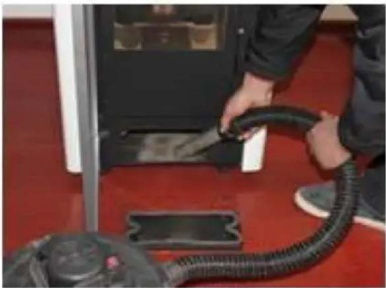
m) To clean the inside of the stove, it is recommended to use a specialist vacuum cleaner for (cold) ash.
n) Cleaning the heart - frequency approximately every 10 burnt bags of pellets:
- Open the furnace door, remove the hearth and clean it thoroughly, especially the holes in it, e.g. using a screwdriver.
- When cleaning the hearth, carefully and delicately clean the ceramic burner.
- When putting the hearth back in its place, make sure that it fits exactly into the hole, so that its upper side is at the front of the stove.
natural_image
Close-up of a hand inserting a plastic bag into a black plastic container (no text or symbols visible)o) Cleaning the glass:
- Never open the front door and do not clean the glass while the oven is in operation, especially when it is hot.
- Clean the cooled glass with paper towels and some glass cleaner.
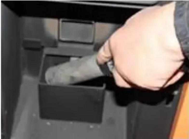
p) Cleaning the ash container:
CAUTION: never open the ash container when the stove is hot!
- Open the stove door and loosen the latches of the ash container at the bottom.
• Pull out the container and empty it of ash. - Remove any remains with a specialist ash vacuum cleaner.
- When inserting the ash container, make sure that it fits accurately and tightly. Otherwise, the sensor may detect the absence of the container and turn the stove off as a result.
natural_image
Person applying a black rubber hose to a white electronic device on red carpet (no visible text or symbols)q) Recommended standard cleaning intervals:
• Hearth - after each 5 bags of pellets
• Ash container - after each 10 bags
• Exhaust fan - after each 100 bags
- Blowing air fan - after each 50 bags
Remove the used batteries from the remote control in the same way as you installed them.
Return the batteries to a unit responsible for their disposal.
DISPOSAL OF WASTE APPLIANCES
At the end of its useful life, this product should not be disposed of with normal household waste but should be taken to a collection point for the recycling of electrical and electronic equipment. This is indicated by the symbol on the product, operating instructions or packaging. The materials used in this appliance are recyclable according to their marking. By reuse, recycling or applying other forms of use of waste machines, you make a significant contribution to the protection of our environment.
Your local administration will provide you with information about the appropriate disposal point for used appliances.
Troubleshooting
The list contains common problems with the device. Before contacting the manufacturer's service, it is recommended to check whether the problem can be solved by yourself.
| Problem | Possible cause | Solution |
| 1. The power LED does not light up when the power is turned on. | No power to the oven or control panel. | Check the power supply and wiring connections. |
| The fuse is defective. | Replace the fuse on the switch or on the control panel. | |
| 2. The display screen does not light up and a beep is heard when the power is turned on. | Loose cable connection. | Check and connect properly. |
| Cable failure or damage. | Replace the cable (only a qualified electrician can do the replacement) or contact the manufacturer's service department. | |
| 3. The display screen does not turn on when the power is on. | See problem (1) and (2). | See problem (1) and (2). |
| The display is damaged. | Replace the display or contact the manufacturer's service department. | |
| 4. The flow fan does not work when the oven is turned on. | After successful ignition, the flow fan will start working. | Wait for a while. |
| The smoke detector is not properly attached. | Correctly fix the smoke detector or contact the manufacturer's service department for repair. | |
| 5. The auger shaft does not feed pellets. | This is normal during the ignition phase. 20 seconds after switching it on, it will start feeding the batch.There is a problem with the connection between the feeding engine and the auger shaft. | Wait for a whileA. Check that the screws between the auger shaft and the engine are not loose or do not fit.B. Check that the auger shaft engine is not damaged or that the cable is properly connected. |
| No fuel in the tank. | Pour fuel into the tank. | |
| The auger shaft channel is blocked. | Check that the auger shaft pipe is not blocked. | |
| The auger shaft engine is defective. | Contact the manufacturer's service department. | |
| 6. Incorrect load amount. | Too much pellet to burn in the required time. | Adjust the batch feed setting to -2 or -1 depending on actual conditions (the factory default setting is 3). |
| Not enough pellets for proper combustion. | Adjust the batch feed setting to +2 or +1 (the factory default setting is 3). | |
| 7. 15 minutes after ignition, the oven shuts down automatically and displays an ignition error (error code: E3) | Lack of pellets or feeding of pellets is not effective enough, which causes ignition failure. | Check the auger shaft system and that the tank is empty. |
| The smoke detector cannot correctly detect the temperature of the smoke. | The smoke detector is damaged or improperly attached, contact the manufacturer for smoke detector replacement or repair. | |
| 8. The flame is smaller.Pellets are not burning enough. Dust has accumulated on the glass. | Not enough air in the combustion chamber | 1. Check, the sealing properties of the sealing strip on the door.2. Check that the inlet pipe or exhaust pipe is not clogged3. Increase the exhaust fan speed to -5 or +5 (default 0)4. If necessary, contact the manufacturer's service. |
| 9. The flame goes out and the message on the display about the lack of pellets (error code: E3). | No charge (pellets) | See problem (5) |
| Too little pellet results in too low a smoke temperature. | Adjust the batch feeding time. | |
| 10. Heating too weak. | The heat exchange pipes are dusty. | Clean the heat exchange tube. |
| 11. Faulty ambient temperature sensor (error code: E1). | The room temperature sensor is damaged or incorrectly attached. | Repair the sensor, correct the installation method, or contact the manufacturer's service department. |
| 12. Smoke sensor defective (error code: E2). | The smoke detector is defective or not attached properly. | Repair the sensor, correct the installation method, or contact the manufacturer's service department. |
| 13. When you turn on the power, you may notice that the fuse in the switch is defective. | A short circuit in the device. | Contact the manufacturer's service department. |
| 14. The exhaust fan does not work, but the flow fan works when the oven is turned on. | Incorrect connection of the exhaust fan and the flow fan. | Replace the exhaust fan and flow-through fan connection. |
| 15. The auger shaft works continuously. | Auger shaft engine failure. | Contact the manufacturer's service department. |
| Check the device for a major failure. | Contact the manufacturer's service department. | |
| 16. The display shows the high temperature in the room (ovens with thermo-circulation). | Ambient temperature sensor defective | See problem (11). |
| An ambient temperature sensor mounted too close to high-temperature objects. | Place the ambient temperature sensor away from high-temperature objects. |

A - min. 2,6 m
B – dystans >1,5 m
C – dystans <1,5 m
natural_image
Three-panel photo showing hands holding wire and wires in a lab setting, one with a red circle highlighting a device (no visible text or symbols)natural_image
Two-panel image showing hands using a black electronic device to install a black plastic clip or bracket (no text or symbols visible)natural_image
Close-up of a black mechanical component with a green checkmark arrow pointing to it (no text or symbols visible)
natural_image
Close-up of a black rectangular object with a red 'X' mark on the side, against a textured background (no text or symbols)
natural_image
Close-up of a hand inserting a plug into a black plastic container (no text or symbols visible)natural_image
Person applying a black rubber hose to a white electronic device on red flooring (no visible text or symbols)A - min. 2,6 m
natural_image
Three-panel photo showing hands holding wire and wires in a lab setting, one with a red circle highlighting a device (no visible text or symbols)natural_image
Two-panel image showing hands using a black electronic device to install a black clip or clip mounted on a stand, with no visible text or symbols.natural_image
Close-up of a black mechanical component with a green checkmark arrow pointing to it (no text or symbols visible)
natural_image
Close-up of a black rectangular object with a red 'X' mark on the side, against a textured background (no text or symbols)natural_image
Close-up of a hand inserting a plastic bag into a black plastic tray (no text or symbols visible)o) Čištění skla:
natural_image
Person applying a black rubber hose to a white electronic device on red carpet (no visible text or symbols)A - min. 1,3 m
B - distance >1,5 m
C - distance <1,5 m
A - min. 2,6 m
B - distance >1,5 m
C - distance <1,5 m
natural_image
Three-panel photo showing hands holding wires and a small electronic device, no visible text or symbolsnatural_image
Two-panel image showing hands using a black plastic device to secure a cable or cable being inserted into a black plastic clip (no text or symbols visible)natural_image
Close-up of a black plastic container with a green checkmark arrow pointing to it (no text or symbols visible)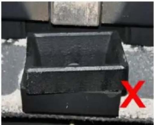
natural_image
Black rectangular object with a circular hole, placed on a textured surface with a red 'X' mark in the corner (no text or symbols on the object itself)natural_image
Close-up of a hand inserting a plug into a black plastic container (no text or symbols visible)natural_image
Person applying a black rubber hose to a white electronic device on red carpet (no visible text or symbols)A - min. 1,3 m
B - distanza >1,5 m
C - distanza <1,5 m
A - min. 2,6 m
B - distanza >1,5 m
C - distanza <1,5 m
natural_image
Three-panel image showing hands holding wire and wires in a lab setting, one with a red circle highlighting a device (no visible text or symbols)natural_image
Two-panel image showing hands using a black electronic device to install a black plastic clip or bracket (no text or symbols visible)natural_image
Close-up of a hand inserting a black plastic bag into a black plastic container (no text or symbols visible)natural_image
Person refueling a black rubber hose on a red floor, with a small electronic device nearby (no visible text or symbols)A - mín. 1 m
B - distancia >1,85 m
A - mín. 1,3 m
B - distancia >1,5 m
A - mín. 2,6 m
B - distancia >1,5 m
natural_image
Three-panel image showing hands holding wire and wires in a lab setting, with one device circled (no visible text or symbols)natural_image
Two-panel image showing hands using a black electronic device to secure a cable or cable being inserted into a black bracket (no text or symbols visible)natural_image
Close-up of a black mechanical component with a green checkmark arrow pointing to it (no text or symbols visible)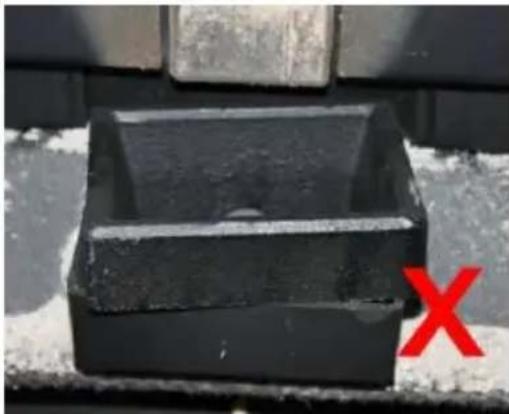
natural_image
Black rectangular object with a circular hole, placed on a textured surface with a red 'X' symbol in the corner (no text or symbols on the object itself)natural_image
Close-up of a hand inserting a plug into a black plastic container (no text or symbols visible)natural_image
Person applying a black rubber hose to a red floor, with a vacuum cleaner visible nearby (no text or symbols)A - min. 1 m
A - min. 1,3 m
B - távolság >1,5 m
C - távolság <1,5 m
A - min. 2,6 m
B - távolság >1,5 m
C - távolság <1,5 m
natural_image
Three-panel photo showing hands holding wire and wires in a lab setting, one with a red circle highlighting a device (no visible text or symbols)natural_image
Two-panel image showing hands using a handheld device to install a black electronic device on a table (no visible text or symbols)natural_image
Close-up of a black mechanical component with a green checkmark arrow pointing to it (no text or symbols visible)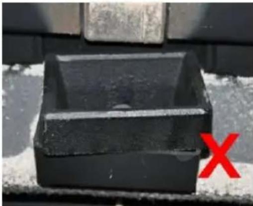
natural_image
Close-up of a black rectangular object with a red 'X' mark on the side, against a textured gray background (no text or symbols)natural_image
Close-up of a hand using a tool to clean or wash a dark plastic tray inside a black plastic container (no text or symbols visible)natural_image
Person refueling a black rubber hose on a red floor, with a gas stove visible in the background (no text or symbols)APPARATETS PLACERING
A - min. 2,6 m
B - afstand > 1,5 m
C - afstand <1,5 m
A - min. 2 m
B - afstand > 1,3 m
C - afstand <1,3 m
natural_image
Three-panel photo showing hands holding wire and wires in a lab setting, one with a red circle highlighting a device (no visible text or symbols)natural_image
Two-panel image showing hands using a black electronic device to install a black plastic clip or bracket (no text or symbols visible)natural_image
Close-up of a black mechanical component with a green checkmark arrow pointing to it (no text or symbols visible)
natural_image
Close-up of a black rectangular object with a red 'X' mark on the side, against a textured background (no text or symbols)natural_image
Close-up of a hand inserting a plastic bag into a black plastic container (no text or symbols visible)natural_image
Person applying a black rubber hose to a white electronic device on red carpet (no visible text or symbols)Olen sisällä. 2,6 m
B - etäisyys >1,5 m
C - etäisyys <1,5 m
natural_image
Three-panel photo showing hands holding wire and wires in a lab setting, one with a red circle highlighting a device (no visible text or symbols)natural_image
Two-panel image showing hands using a black electronic device to install a cable or cable clamp (no text or symbols visible)natural_image
Close-up of a black mechanical component with a green checkmark arrow pointing to it (no text or symbols visible)
natural_image
Close-up of a black rectangular object with a red 'X' mark on the side, against a textured gray background (no text or symbols)natural_image
Close-up of a hand inserting a black plastic bag into a black plastic container (no text or symbols visible)o) Lasin puhdistus:
natural_image
Person using a black rubber hose to clean or install a white box on a red floor (no visible text or symbols)natural_image
Close-up of a black plastic container with a green checkmark arrow pointing to it (no text or symbols visible)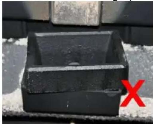
natural_image
Close-up of a black plastic container with a red 'X' mark on the side (no text or symbols on the container itself)natural_image
Close-up of a hand inserting a plug into a black plastic container (no text or symbols visible)natural_image
Person using a black vacuum cleaner on a red floor, no visible text or symbols- Styrepanel
- Beholderlokk
- Hopper
- Mark
- Snekkemotor
- Tenner
- Luftinntaksrør
- Eksosrør (til skorsteinen)
- Vifte vifte
- Avtrekksvifte
- Varmeuttak
- Ildsted
- Knott
- Spiralblader
-
Askebeholder
-
PÅ/AV-bryter (på baksiden av huset ved siden av strømledningen - ikke synlig på bildet)
MSW-PLT-6:
- Styrepanel
- Beholderlokk
- Hopper
- Mark
- Snekkemotor
- Tenner
- Luftinntaksrør
- Eksosrør (til skorsteinen)
- Vifte vifte
- Avtrekksvifte
- Varmeuttak
- Ildsted
-
Askebeholder
-
PÅ/AV-bryter (på baksiden av huset ved siden av strømledningen - ikke synlig på bildet)
A - min. 1,3 m
B - avstand >1,5 m
C - avstand <1,5 m
A - min. 2,6 m
B - avstand >1,5 m
C - avstand <1,5 m
A - min. 2 m
B - avstand >1,3 m
C - avstand <1,3 m
D - 0,5 m over takets høyeste punkt
E - 2,1 m
F - dreneringsområde
natural_image
Three-panel photo showing hands holding wire and wires in a lab setting, one with a red circle highlighting a device (no visible text or symbols)natural_image
Two-panel image showing hands using a black electronic device to install a black plastic clip or bracket (no text or symbols visible)natural_image
Close-up of a black metal container with a green checkmark arrow pointing to it (no text or symbols visible)
natural_image
Close-up of a black rectangular object with a red 'X' mark on the side, against a textured background (no text or symbols)d) Temperaturinnstilling
natural_image
Close-up of a hand inserting a dark plastic bag into a black plastic tray (no text or symbols visible)natural_image
Person applying a black rubber hose to a white cabinet on red carpet (no visible text or symbols)q) Anbefalte standard rengjøringsintervaller:
Är i. 2,6 m
B - avständ >1,5 m
C - avstånd <1,5 m
natural_image
Three-panel image showing hands holding wire and wires in a lab setting, one with a red circle highlighting a device (no visible text or symbols)Installation av kontrollpanelen:
natural_image
Two-panel image showing hands using a black electronic device to install a black plastic clip or bracket (no text or symbols visible)natural_image
Close-up of a black mechanical component with a green checkmark arrow pointing to it (no text or symbols visible)
natural_image
Close-up of a black rectangular object with a red 'X' mark on the side, against a textured gray background (no text or symbols)R - min. 2,6 metros
natural_image
Close-up of a black plastic container with a green checkmark arrow pointing to it (no text or symbols visible)
natural_image
Black rectangular object with a horizontal line and a red 'X' mark on the side, placed on a textured surface (no text or symbols visible)A - min. 2,6 m
B - vzdialenost' >1,5 m
C - vzdialenost' <1,5 m
natural_image
Three-panel photo showing hands holding wire and wires in a lab setting, one with a red circle highlighting a device (no visible text or symbols)natural_image
Two-panel image showing hands using a black electronic device to install a black plastic clip or bracket (no text or symbols visible)natural_image
Close-up of a black mechanical component with a green checkmark arrow pointing to it (no text or symbols visible)
natural_image
Close-up of a black rectangular object with a red 'X' mark on the side, against a textured background (no text or symbols)natural_image
Close-up of a hand inserting a plug into a black plastic container (no text or symbols visible)o) Čistenie skla:
natural_image
Person applying a black rubber hose to a white electronic device on red flooring (no visible text or symbols)For the disposal of the device please consider and act according to the national and local rules and regulations.
CONTACT
expondo Polska sp. z o.o. sp. k.