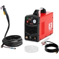
S-Plasma 50 - Welding machine Stamos - Free user manual and instructions
Find the device manual for free S-Plasma 50 Stamos in PDF.


| Product type | Welding machine / plasma cutter |
| Brand | Stamos |
| Model | S-Plasma 50 |
| Supply voltage | 230 V ~ / 50 Hz |
| Cutting current | 25 - 50 A |
| No-load voltage | 300 V |
| Rated duty cycle | 30 % (over 10 min period) |
| Cutting current at 100% duty cycle | 27 A |
| Protection rating | IP21S |
| Arc ignition | HF |
| Supply air pressure | 3.5 - 5.5 bar |
| Standards compliance | EN60974-1 |
| Dimensions (L x W x H) (estimated) | 370 x 160 x 270 mm |
| Weight (estimated) | 10 kg |
| Operating ambient temperature | -10 °C to 40 °C |
| Cleaning and maintenance | Disconnect before cleaning; use non-corrosive agents; drain the gas filter regularly |
| Safety | Thermal overload protection; mandatory personal protective equipment (mask, gloves, clothing) |
| Spare parts and repairability | Repairs reserved for manufacturer service; use original spare parts |
| Warranty | Respect the duty cycle; warranty void if misused |
Frequently Asked Questions - S-Plasma 50 Stamos
User questions about S-Plasma 50 Stamos
0 question about this device. Answer the ones you know or ask your own.
Ask a new question about this device
Download the instructions for your Welding machine in PDF format for free! Find your manual S-Plasma 50 - Stamos and take your electronic device back in hand. On this page are published all the documents necessary for the use of your device. S-Plasma 50 by Stamos.
USER MANUAL S-Plasma 50 Stamos
E - Werkstück
This User Manual has been translated for your convenience using machine translation. Reasonable efforts have been made to provide an accurate translation; however, no automated translation is perfect nor is it intended to replace human translators. The official User Manual is the English version. Any discrepancies or differences created in the translation are not binding and have no legal effect for compliance or enforcement purposes. If any questions arise related to the accuracy of the information contained in the User Manual, please refer to the English version of those contents which is the official version.
Symbols
| Read the manual. | |
| Recyclable product. | |
| The product meets the requirements of relevant safety standards. | |
| Wear protective clothing protecting the whole body. | |
| Caution! Wear safety gloves. | |
| Wear safety goggles | |
| Use safety shoes. | |
| Caution! Hot surface – risk of burns! | |
| Caution! Risk of fire or explosion. | |
| Caution! Harmful fumes, danger of poisoning. Gases and fumes can be hazardous to health. | |
| Use a welding mask with an appropriate degree of filter blackout. | |
| CAUTION! Harmful electric arc radiation | |
| Do not touch live parts |

The figures in this manual are illustrative only and may vary in some details from the actual appearance of the equipment.

CAUTION! Read all safety warnings and all instructions. Failure to follow the warnings and instructions may result in electric
shock, fire and/or serious injury or death.
The term "equipment" or "product" in the warnings and instructions refers to the:
Plasma Cutter
1. OPERATING SAFETY
1.1. GENERAL NOTES
a) Take care of own safety and of safety of bystanders by familiarising oneself with and following the guidelines contained in the device manual.
b) Only qualified personnel may be allowed to start, use and operate the equipment.
c) Repairs should be carried out by the manufacturer's service personnel using original parts only.
d) Do not allow bystanders, including minors, to access the equipment during its use.
e) Plasma cutter is equipment intended for cutting metal. Do not use this equipment contrary to its intended purpose.
f) During operation the equipment produces electromagnetic field around it which may cause incorrect operation of medical implants, i.e. pacemakers, etc.
g) It is forbidden to point the gun towards yourself, other people or animals.
h) Take care of regular service and maintenance.
i) Before each adjustment, maintenance, nozzle replacement, etc., disconnect the equipment from the power supply.
j) Do not use the product with the housing removed.
k) All waste generated during cutting must be disposed of in accordance with local regulations.
1.2. PREPARATION OF WORKPLACE FOR CUTTING
Caution! Cutting may cause fire or explosion. Plasma stream throws out incandescent metal particles or sparks. Hot metal particles, sparks, a heated element or a hot burner may cause fire. Therefore carefully check the surroundings of the workplace for safety.
a) Remove all combustible materials within a radius of 12 m from the burner.
b) If this is not possible, flammable materials should be secured with a suitable cover.
c) It is forbidden to cut in places where flammable materials may ignite.
d) Safety measures should be taken to avoid beams of sparks and glowing metal particles.
e) Note that sparks or hot metal chips may enter through gaps or holes.
f) Pay close attention to electric arc and have a fire extinguisher in close range.
g) Pay attention to the fact that cutting at the ceiling, on the floor or between the separated space can cause a flame outbreak on the other side that is invisible.
h) Always take care of sufficient ventilation.
i) Use the equipment at ambient temperature between -10 and 40°C, in a room with low humidity and dust concentration, without direct exposure to sunlight.
j) If cutting is made in a place where there are sudden air movements, use a wind shield.
k) Before cutting, take a stable position.
I) Do not use plasma torch to warm frozen pipes.
m) Do not cut with plasma near combustible materials/tanks. Flammable materials or tanks must be removed or thoroughly emptied.
n) Do not cut with plasma in an atmosphere containing combustible particles or fumes of explosive substances.
o) Do not plasma cut pressurised tanks, pressure system lines or pressure containers.
p) Place the plasma cutting station away from flammable surfaces.
q) Before cutting with plasma, dispose of flammable or explosive items, such as butane propane lighters or matches.
r) Observe the occupational health and safety regulations for welding works and equip the work station with a suitable fire extinguisher. The flame and operating circuit are live if electrical supply is switched on. The input circuit and internal circuit of the equipment are also live, provided that electrical supply is switched on.

Caution! Cutting near tanks or barrels with flammable substances is prohibited.

Note! Keep children and other bystanders safe while operating the equipment.
1.3. PERSONAL PROTECTIVE EQUIPMENT
Caution! Splashes and sparks can cause injury.
a) Always wear a protective mask or glasses with a side cover.
b) Always wear suitable protective clothing to protect the body.
c) Always wear earplugs or other hearing protection to avoid spatter entering ears.
d) Electric arc in the cutting process produces large amounts of visible and invisible radiation (ultraviolet and infrared radiation) which can cause damage to sight and skin.
e) When cutting with plasma, wear clean, oil-free protective clothing, e.g. leather gloves, thick shirt, trousers without wrapped legs, high shoes and protective hood.
f) Use face protection (helmet or shield) and eye protection with a proper coloured eyepiece that performs the function of a filter and protects eyes during cutting.
g) Safety standards suggest colouring no. 9 (minimum no. 8) for each current below 300 A. Lower colouring of the cover can be used if arc covers the workpiece.
h) Always use approved safety glasses with side shield under the helmet or other cover.
i) Use workplace guards to protect other people from blinding light radiation or splashes.
j) Bystanders should be warned against looking at electric arc.
k) For people with a pacemaker or other implanted medical device, it is not recommended to use the equipment without first consulting a doctor.

NOTE! Radiation of electric arc may cause damage to sight and skin.
1.4. ELECTRIC SHOCK PROTECTION
Caution! Electric shock can be fatal.
a) The power cable should be connected to the nearest socket and laid in a practical and safe manner. Avoid negligent routing of the cable in the room on an untested ground, which may lead to electric shock or fire.
b) Contact with electrically charged elements may cause electric shock or severe burns.
c) Electric arc and working area during current flow are electrically charged.
d) The input circuit and the internal current circuit of the equipment are also live with power on.
e) Do not touch live objects.
f) Wear dry, non-punctured, insulated gloves and protective clothing.
g) Use insulating mats or other insulation coatings on the floor that are large enough to prevent body contact with the object or floor.
h) Do not touch electric arc.
i) Before operation, cleaning or replacing the electrode turn off power supply.
j) Make sure that the ground wire is properly connected and that the plug is properly connected to the grounded socket. Improper connection of grounding of the equipment may cause a threat to life or health.
k) Check current cables regularly for damage or lack of insulation. Replace damaged cables. Careless insulation repair may cause death or loss of health.
I) When the product is not used, turn off all input power supply units.
m) The cable must not be wrapped around the body.
n) The workpiece being cut must be properly grounded.
o) Only use accessories which are in good condition.
p) Damaged parts of the equipment must be repaired or replaced.
q) When working at heights, use safety belts.
r) All accessories and safety elements should be stored in one place.
s) When the trigger is activated, keep the handle tip away from the body.
t) Attach the working cable to the correct metal contact of the cut element (not to an element that may fall off) or to the work table close enough to the plasma cutter, as far as it seems intentional.
u) The working clamp must be insulated unless it is connected to the workpiece in order to avoid contact with the metal surface.
v) The product is intended for indoor work. However, if it was exposed to moisture or rain, check whether water droplets did not get inside, which may result in an accident.
w) After switching off the equipment and disconnecting the power cable, check voltage on the input capacitor and make sure that the voltage value is zero. Otherwise do not touch the equipment components.
x) The equipment must not get wet.

NOTE! After disconnecting the power cable, the equipment may still be live.

NOTE! Although the equipment has been designed to be safe and has been provided with adequate safeguards, and despite the use of additional safety measures, there is still a low, residual risk of accident or injury during its operation. Caution and common sense are advised when using the product.
- TECHNICAL DATA
| Product name | Plasma Cutter | |
| Model | S-PLASMA50U | S-PLASMA 60U |
| Rated supply voltage [V~] / Frequency [Hz] | 230/50 400/500 | |
| Cutting current | 25-50A | 25-65 |
| Idle voltage [V] | 300 | 310 |
| Rated duty cycle | 30% | 30% |
| Cutting current at 100% operation cycle | 27A | 36A |
| Ingress protection | IP21S | IP21S |
| Arc ignition | HF | HF |
| Supply air pressure [bar] | 3,5-5,5 | 4-6 |
| Compliance with standards | EN60974-1 | EN60974-1 |
| S-PLASMA50U | |||
| Work cycle | 30% | 60% | 100% |
| Measured input power | 5 834 | 3 682 | 2 848 |
| Measured output power | 5 064 | 3 258 | 2 550 |
| Calculated efficiency % | 86 | 87 | 88 |
| Minimum calculated performance | 86 | ||
| Power measurement at rest | |||
| Ambient temperature | 20°C | ||
| Input voltage | 230V | ||
| Frequency | 50Hz | ||
| Test time | 10 min | ||
| Measured input data at the beginning | 16.99W | ||
| Measured input data at the end | 15.28W | ||
| S-PLASMA60 U | |||
| Work cycle | 30% | 60% | 100% |
| Measured input power | 7 764 | 5 108 | 3 812 |
| Measured output power | 6 850 | 4 540 | 3 376 |
| Calculated efficiency % | 87 | 88 | 88 |
| Minimum calculated performance | 87 | ||
| Power measurement at rest | |||
| Ambient temperature | 20°C | ||
| Input voltage | 230V | ||
| Frequency | 50Hz | ||
| Test time | 10 min | ||
| Measured input data at the beginning | 18.85W | ||
| Measured input data at the end | 17.57W | ||
3. OPERATION
3.1. GENERAL NOTES
- Use the equipment as intended, in accordance with OHS regulations and restrictions resulting from data on the nameplate (IP code, power supply voltage, etc.).
-
The manufacturer shall not be liable for technical changes of the equipment or material damage resulting from the introduction of these changes.
-
If the equipment malfunctions, contact the service centre.
- Do not cover the ventilation slots – set the equipment at a distance of 20 cm from the wall and 30 cm from the surrounding objects.
- The inclination of the surface on which the equipment is set should not exceed 15 degrees.
- Protect the equipment from rain, moisture and direct sunlight.
- Do not direct the stream of sparks at the equipment.
- Do not hold the equipment under the arm or near the body.
- Do not install the equipment in rooms with aggressive environment, high dustiness, and near devices with high electromagnetic field emission.
- Keep fingers, hair and clothing away from the rotating fan.
- The equipment must be grounded during operation.
- When the thermal overload LED lights up during operation, stop working immediately and wait until the equipment cools down.
- When the equipment is used for a long time or at high current, switch off the power supply only after the equipment has cooled down.
- Do not switch off the equipment during cutting!
- Regularly maintain the equipment and clean it from dust.
DUTY CYCLE:
The activation time is a percentage of the operating time (measured in minutes) during a period of 10 minutes in which the equipment operated continuously under conventional temperature conditions. If the activation time is exceeded, the safety system will trip and will turn off the equipment to cool it down to normal operating temperature. Exceeding the activation time threshold may result in damage to the device and loss of warranty.
3.2. EQUIPMENT CONNECTION
- The equipment should be connected by a qualified person. In addition a person with the necessary qualifications should check whether the grounding and electrical system, together with the protection system, comply with the safety regulations and function properly.
- Position the equipment near the workplace.
- Avoid too long cable when connecting the equipment. An excessively long cable with a small cross-section will cause voltage drops and incorrect operation of the equipment.
- Single-phase plasma cutters should be connected to a socket provided with a grounding pin.
CAUTION! OPERATE THE EQUIPMENT ONLY WHEN IT IS CONNECTED TO A SYSTEM WITH AN OPERATIONAL FUSE!
NOTE: when starting a power generator, the cutter should be disconnected from the power supply!
4. EQUIPMENT DESIGN
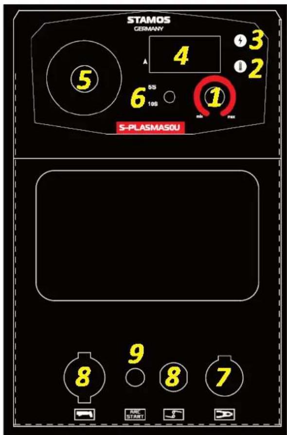
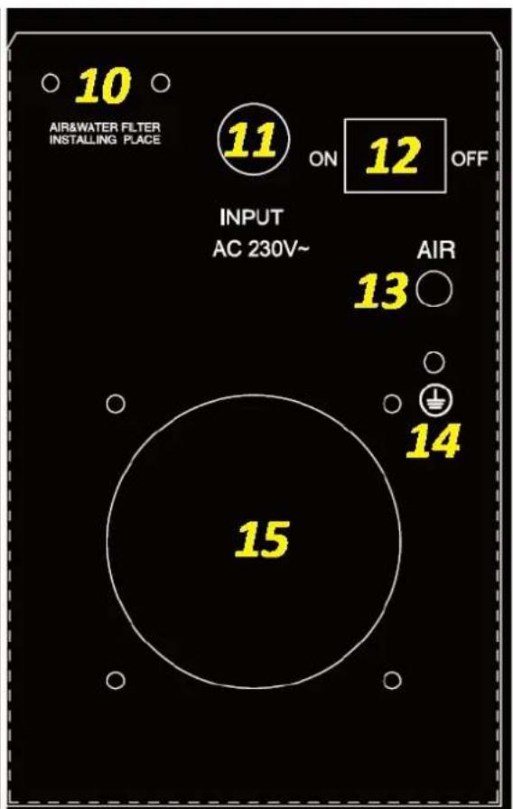
Front view / rear view S-PLASMA50U
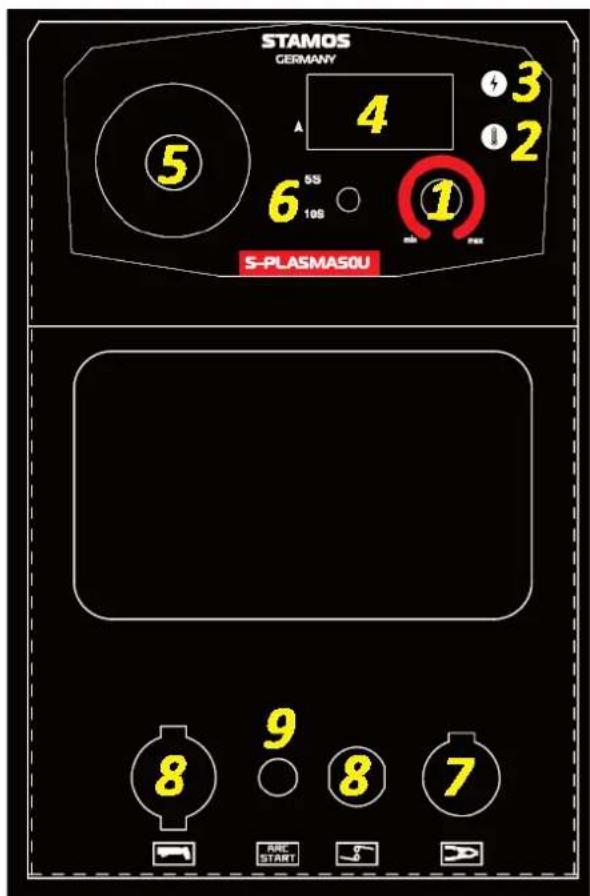
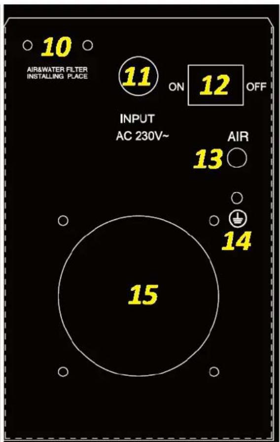
1 - Cutting current adjustment knob
2 - Overheat indicator light
3 - Power indicator light
4 – Cutting current display
5 - Manometer
6 - Post-cutting gas release time switch - 5 s / 10 s
7 – Grounding wire connector
8 – Plasma burner current and gas connector
9 – Plasma burner control cable connector
10 – Place of assembly of the filtering and reducing unit:
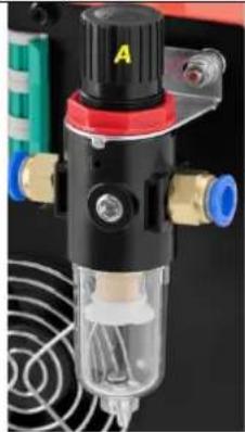
A – gas pressure adjustment knob Installation of the filtering and reducing unit:
- Screw the copper gas nozzles into the gas inlet and outlet holes.
- Using bolts and nuts, screw the filter-reduction unit holder to the frame at the back of the plasma cutter.
- Install the filtering and reducing unit in the holder and secure the connection with a nut.
- Connect the compressor to the gas inlet of the filtering and reducing unit.
- Connect the gas outlet of the filter-reducing assembly with the gas inlet of the plasma cutter (13)
11 – Power supply cable
12 - ON/OFF power switch
13 - Gas inlet
14 - Grounding
15 - Fan
Front view / rear view S-PLASMA 60U
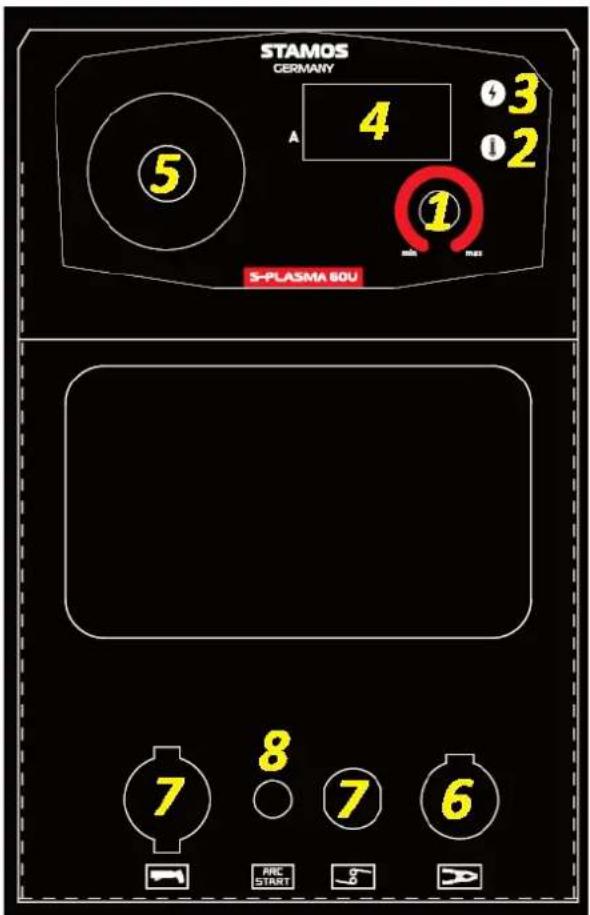
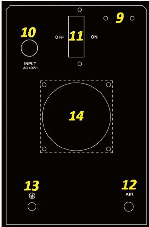
1 - Cutting current adjustment knob
2 - Overheat indicator light
3 - Power indicator light
4 – Cutting current display
5 - Manometer
6 – Grounding wire connector
7 – Plasma burner current and gas connector
8 - Plasma burner control cable connector
9 – Place of assembly of the filtering and reducing unit:
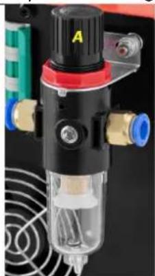
A – gas pressure adjustment knob Installation of the filtering and reducing unit:
- Screw the copper gas nozzles into the gas inlet and outlet holes.
- Using bolts and nuts, screw the filter-reduction unit holder to the frame at the back of the plasma cutter.
- Install the filtering and reducing unit in the holder and secure the connection with a nut.
- Connect the compressor to the gas inlet of the filtering and reducing unit.
- Connect the gas outlet of the filter-reducing assembly with the gas inlet of the plasma cutter (12)
10 - Power supply cable
11-ON/OFF power switch
12 - Gas inlet
13 - Grounding
14 - Fan
5. CABLE CONNECTION
-
Make sure that the ON/OFF switch at the rear of the device is in the "OFF" position. Connect the equipment to the power supply.
-
Make sure that the air pressure adjustment knob [A] is set to minimum. Connect compressed air supply.
CAUTION! Make sure that the power supply parameters and gas pressure are in accordance with the values in the technical data table of this document or with the device nameplate.
-
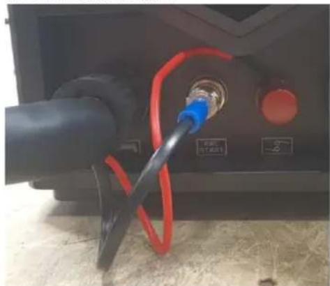
Connect the burner cables to the control connector and the current and gas connector.
-
Connect the grounding wire to the connector, paying special attention to the clamp being firmly attached to the workpiece.
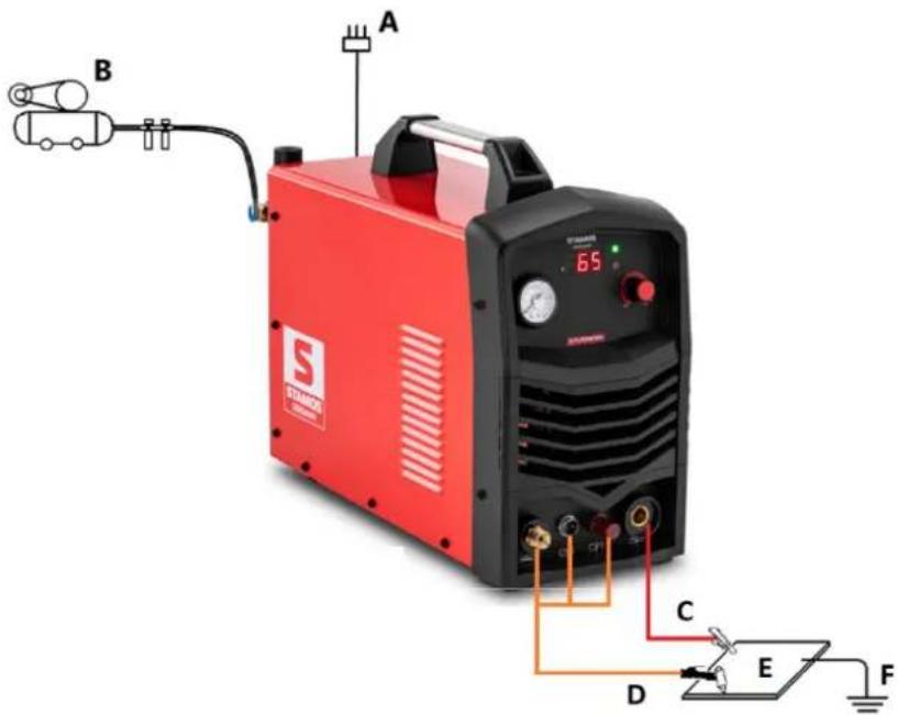
A - Power supply
B - Air compressor
C - Grounding wire
D - Plasma burner cable:
E - Workpiece
F - Additional grounding of the work station
-
Set the ON/OFF switch to ON.
-
Adjust the pressure using the knob on the filtering and reduction unit (lift the knob, rotate it to set the desired pressure, and push to the initial position).
-
Set the appropriate cutting current according to the thickness and requirements of the workpiece process.
-
Press the plasma burner trigger; the noise of evacuating air should be heard.
Note: when triggering the plasma burner, always direct its outlet at a safe place.
-
You can start cutting the material.
-
If the equipment overheats, the protection will trip. Only after the equipment has been cooled can it be restarted.
-
After cutting always turn off the equipment.
7. PACKAGING DISPOSAL
Please keep the packaging elements (cardboard, plastic tapes and polystyrene foam), so that if it is necessary to put the device to service, it can be protected as best as possible for the time of shipment!
8. TRANSPORT AND STORAGE
During transport protect the equipment against shocks and tipping over, and do not place it "upside down". Store the equipment in a well-ventilated room where dry air is present and there are no corrosive gases.
9. CLEANING AND MAINTENANCE
- Before cleaning and when the equipment is not in use, unplug it from the mains and cool it down.
- Use non-corrosive agents only for cleaning the surfaces.
• After each cleaning, all the components should be well dried before the equipment is used again. - Store the equipment in a dry and cool place protected from moisture and direct sunlight.
- When liquid is collected in the gas filter tank, allow it to flow out by opening the valve at the bottom of the tank. Place a suitable container in advance to protect the equipment and the floor from splashing.
NOTE: all works on the equipment should be carried out at least 5 minutes after finishing work, so that the equipment may cool down.
Periodic maintenance
Periodic maintenance is necessary for the equipment to work properly.
CAUTION! Switch off the equipment and disconnect it from the power supply before starting maintenance.
| Regular inspections | 6-month routine maintenance |
| Replace illegible labels.Check the operation of all switches.Check that the fan is working properly and that air escapes at the back of the equipment.Pay attention to excessive vibrations, noise, odour and gas leakage during operation.Check that the burner cables or ground wires are not burnt-out.Check that no electrical connections are burnt-out.Check whether the power cable is not damaged, | Purge the equipment with dry clean compressed air.Check the electrical connections of the input/output strip to tighten loose or replace rusty screws. |

E - Objet traité
E - Megmunkált elem
3.2. TILSLUTNING AF PRODUKTET
4. PRODUKTETS OPBYGNING
Set forfra / Set bagfra: S-PLASMA50U
For the disposal of the device please consider and act according to the national and local rules and regulations.
CONTACT
expondo Polska sp. z o.o. sp. k.
- OPERATING SAFETY
- GENERAL NOTES
- PREPARATION OF WORKPLACE FOR CUTTING
- PERSONAL PROTECTIVE EQUIPMENT
- ELECTRIC SHOCK PROTECTION
- OPERATION
- DUTY CYCLE
- EQUIPMENT CONNECTION
- EQUIPMENT DESIGN
- FRONT VIEW / REAR VIEW S-PLASMA 60U
- CABLE CONNECTION
- PACKAGING DISPOSAL
- TRANSPORT AND STORAGE
- CLEANING AND MAINTENANCE
- PERIODIC MAINTENANCE
- TILSLUTNING AF PRODUKTET
- PRODUKTETS OPBYGNING
- CONTACT
Brand : Stamos
Model : S-Plasma 50
Category : Welding machine