S-WIGMA 200 PRO - Welding machine Stamos - Free user manual and instructions
Find the device manual for free S-WIGMA 200 PRO Stamos in PDF.

User questions about S-WIGMA 200 PRO Stamos
0 question about this device. Answer the ones you know or ask your own.
Ask a new question about this device
Download the instructions for your Welding machine in PDF format for free! Find your manual S-WIGMA 200 PRO - Stamos and take your electronic device back in hand. On this page are published all the documents necessary for the use of your device. S-WIGMA 200 PRO by Stamos.
USER MANUAL S-WIGMA 200 PRO Stamos
text_image
Labeled diagram of a device with numbered parts for identificationnatural_image
Simple line drawing of a gas cylinder connected to a gas collection device with tubing (no text or symbols)| The operation manual must be read carefully. | |
| The product must be recycled. | |
| Satisfies requirements of applicable safety standards. | |
| Use full body protective clothes. | |
| ATTENTION! Wear protective gloves. | |
| Safety goggles must be worn. | |
| Protective footwear must be worn. | |
| ATTENTION! Hot surface may cause burns. | |
| ATTENTION! Risk of fire or explosion. | |
| ATTENTION! Harmful fumes, danger of poisoning. Gases and vapours may be hazardous to health. Welding gases and vapours are released during welding. Inhaling these substances may be hazardous to health. | |
| Use a welding mask with appropriate filter shading. | |
| CAUTION! Harmful welding arc radiation. | |
| Do not touch the parts that are under voltage/power. |
PLEASE NOTE! Drawings in this manual are for illustration purposes only and in some details may differ from the actual product.
The original operation manual is in German. Other language versions are translations from German.
- TECHNICAL SPECIFICATIONS
| Parameter description | Parameter value | |
| Product name | TIG Welder | |
| Model | S-WIG-MA 200 PRO | S-WIG 200 IGBT |
| Voltage/Frequency [V~/Hz] | 230/50 | |
| Rated input current [A] | 16 (MMA) | |
| 15.7 (TIG) | ||
| No-load voltage [V] | 59 (MMA/TIG) | |
| MMA welding current [A] | 10-180 | |
| TIG welding current [A] | 10-200 | |
| Welding current at 20% duty cycle [A] | 180 (MMA) | |
| Welding current at 35% duty cycle [A] | 200 (TIG) | |
| Welding current at 60% duty cycle [A] | 103 (MMA) | |
| 152 (TIG) | ||
| Welding current at 100% duty cycle [A] | 80 (MMA) | |
| 118 (TIG) | ||
- GENERAL DESCRIPTION
The user manual is designed to aid safe and troublefree use. The product is designed and manufactured in accordance with strict technical guidelines, using state of the art technologies and components and in compliance with the most stringent quality standards.
DO NOT USE THE DEVICE UNLESS YOU HAVE THOROUGHLY READ AND UNDERSTOOD THE PRESENT USER MANUAL.
To extend the shelf life of the device and to ensure trouble free operation, use it and perform maintenance tasks in accordance with this user manual. The technical data and specifications in this user manual are current. The manufacturer reserves the right to make changes associated with quality improvements. Taking into account technological progress and noise reduction opportunities, the device was designed to reduce noise emission risk to the minimum.
- SAFETY OF USE
ATTENTION! Read all safety warnings and all instructions. Failure to follow the warnings and instructions may result in an electric shock, fire and/or serious injury or death.
3.1. GENERAL NOTES
• Take care of your own safety and the one of third parties by reading and strictly following the instructions, included in the operating manual of the device.
- Only qualified and skilled personnel can be allowed to start, operate, maintain and repair the machine.
- The machine must never be operated contrary to its intended purpose.
3.2. SECURITY GUIDELINES FOR WORK THAT CONSTITUTES A FIRE HAZARD Preparation of the building and premises for work that constitutes a fire hazard:
- removal of all flammable materials and waste from rooms and premises where work will be carried out;
- moving any flammable objects and non-flammable objects in flammable packages away to a safe distance;
- materials that cannot be removed must be secured against e.g. welding spatter by covering them with e.g. metal sheets, drywall, etc.;
- check if materials or flammable objects in surrounding rooms require protection;
- seal with non-flammable materials any openings in installation, ventilation, etc. located near the place of work;
- secure electric cables, gas or installation pipes covered with flammable insulation against welding spatter if they are within the range of work that constitutes a fire hazard;
- check that the planned work will not be carried out in rooms that were painted using flammable substances or where other flammable substances were used on the day of planned work.
SPARKS MAY CAUSE A FIRE
Sparks produced by welding can cause fires, explosions and burns on exposed skin. During welding, it is necessary to wear welding gloves and protective clothing. Remove or secure any flammable materials and substances from the place of work. Do not weld sealed containers or tanks in which flammable liquids were stored.
EN EN
Such containers or tanks must be rinsed before welding to remove flammable liquids. Do not weld in the vicinity of flammable gas, vapours or liquids. Fire equipment (blankets, dry powder extinguisher or extinguishing loam) must be placed near the workplace in an easily visible and reachable place.
A CYLINDER MAY EXPLODE
Use only approved gas cylinders and a properly working reducer. The cylinder should be transported, stored and placed in a vertical position. Protect the cylinders from heat sources, tipping over and mechanical damage. Maintain all gas installation elements: cylinder, hose, fittings, reducer in good condition.
WELDED MATERIALS CAN CAUSE BURNS
Never touch the welded components with parts of your body without protection. When touching and moving welded material, always use welding gloves and tongs.
3.3. PREPARATION OF WELDING WORK SITE
WELDING OPERATIONS MAY CAUSE FIRE OR EXPLOSION!
- Strictly follow the occupational health and safety regulations applicable to welding operations and make sure to provide appropriate fire extinguishers at the welding work site.
- Never carry out welding operations in flammable places that pose the risk of material ignition.
- It is prohibited to weld in the presence of an explosive mixture of combustible gases, vapours, mists or dust with air.
- Remove all flammable materials within 12 meters from the welding operations site and if removal is not possible, cover flammable materials with fire retardant covering.
- Use safety measures against sparks and glowing metal particles.
- Make sure that sparks or hot metal splinters do not penetrate through the slots or openings in the coverings, shields or protective screens.
- Do not weld tanks or barrels that contain or have contained flammable substances. Do not weld in the vicinity of such containers and barrels.
- Do not weld pressure vessels, pipes of pressurised installations or pressure trays.
• Always ensure adequate ventilation.
- It is recommended to take a stable position prior to welding.
3.4. PERSONAL PROTECTION EQUIPMENT
ELECTRIC ARC RADIATION CAN CAUSE DAMAGE TO EYES AND SKIN!
- When welding, wear clean, oil stain free protective clothing made of non-flammable and nonconductive materials (leather, thick cotton), leather gloves, high boots and protective hood.
- Before welding remove all flammable or explosive items, such as propane butane lighters or matches
- Use facial protection (helmet or shield) and eye protection, with a filter featuring a shade level matching the sight of the welder and the welding current. The safety standards suggest colouring No. 9 (minimum No. 8) for each current below 300 A. A lower shield colouring can be used if the arc is covered by the workpiece.
• Always use approved safety glasses with side protection under the helmet or any other cover.
- Use guards for the welding operation sites in order to protect other people from the blinding light radiation or projections.
• Always wear earplugs or another hearing protection to protect against excessive noise and to avoid spatter entering the ears.
• Bystanders should be warned to not look at the arc.
3.5. PROTECTION AGAINST ELECTRIC SHOCK
ELECTRIC SHOCK CAN BE LETHAL!
- The power cable must be connected to the nearest socket and placed in a practical and secure position. Positioning the cable negligently in the room and on a surface which was not checked must be avoided, as it can lead to electrocution or fire.
- Touching electrically charged elements can cause electrocution or serious burns.
• The electrical arc and the working area are electrically charged during the power flow.
- The device's input circuit and inner power circuit are also under voltage charge when the power supply is turned on.
- The elements under the voltage charge must not be touched.
- Dry, insulated gloves without any holes and protective clothing must be worn at all times.
- Insulation mats or other insulation layers, big enough as not to allow for body contact with an object or the floor, must be placed on the floor.
- The electrical arc must not be touched. - Electrical power must be shut down prior to cleaning
or electrode replacement.
- It must be checked if the earthing cable is properly connected or the pin is correctly connected to the earthed socket. Incorrectly connecting the earthing can cause life or health hazard.
- The power cables must be regularly checked for damage or lack of insulation. Damaged cables must be replaced. Negligent insulation repair can cause death or serious injury.
• The device must be turned off when it is not in use.
- The cable mustn't be wrapped around the body. - A welded object must be properly grounded.
- Only equipment in good condition can be used. - Damaged device elements must be repaired or replaced. Safety belts must be used when working at height.
- All fittings and safety elements must be stored in one place.
• From the moment of turning on the release, the handle end must be kept away from the body.
- The chassis ground must be mounted to the welded element or as close to it as possible (e.g. to a work table).
THE DEVICE CAN STILL BE UNDER VOLTAGE UPON FEEDER DISCONNECTION!
- The voltage in the input capacitor must be checked upon turning off the device and disconnecting it from the power source. One must make sure that the voltage value is equal to zero. Otherwise, the device elements must not be touched.
- Always keep a certain distance from the gas outlet - When welding, ensure good ventilation. Avoid inhaling the gas.
removed from the surfaces of welded objects as they burn and emit toxic smokes under the influence of temperature.
• The welding of galvanised objects is permitted only when efficient ventilation is provided with filtration and access to fresh air. Zinc fumes are very toxic, an intoxication symptom is the so-called zinc fever.
4. OPERATION
4.1. GENERAL NOTES
- The device must be applied according to its purpose with observance of OHS regulations and restrictions resulting from data included in the rating plate (IP level, operation cycle, supply voltage, etc.).
- The machine must not be opened as it will cause warranty loss and, in addition, exploding. Unshielded elements can cause serious injuries.
• The producer does not bear any responsibility for technical changes in the device or material losses caused by the introduction of the said changes.
- In case of incorrect device operation, contact the service centre.
- Louvers must not be shielded – the welder must be positioned at 30 cm distance from the objects surrounding it.
• The welder must not be kept under your arm or near your body.
- The machine must not be installed in rooms with aggressive environments, high dustiness and near devices with high electromagnetic field emission.
4.2. DEVICE STORAGE
• The machine must be protected against water and moisture.
• The welder must not be positioned on heated surfaces.
• The device must be stored in a dry and clean room.
4.3 CONNECTING THE DEVICE
4.3.1 CONNECTING THE POWER
- The connection of the device must be performed by a qualified person. In addition, a person with required qualifications should check if the carthing or electrical installation with protection system is in line with the safety regulations and if they operate correctly.
• The device must be placed near the work station
- Connecting excessively long conduits to the machine must be avoided.
- One-phase welders should be connected to the socket fitted with an earthing prong.
- Welders powered from a 3-Phase network are delivered without a plug, the plug must be obtained independently and installation should be assigned to a qualified person.
PLEASE NOTE! THE DEVICE MAY ONLY BE USED UPON CONNECTION TO AN INSTALLMENT WITH A PROPERLY FUNCTIONING FUSE.
4.3.2 CONNECTING GAS
• Gas tanks must be placed far from the welded object and be protected against falling.
- Gas connector of the welder must be connected with the tank or gas installation by means of the correct pipe and regulator with gas flow regulation. Please note! Connection of line regulators to the tank and the other way round is prohibited. Such a change can result in regulator damage and serious injuries.
• Economical gas use extends the welding time.
- DEVICE USE+ Chemical substances (lubricants, solvents) must be
text_image
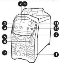
Labeled diagram of a device with numbered parts for identificationNo. Function and description
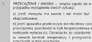
- ERROR INDICATOR = The indicator lights in the following two situations: a) if the machine has malfunctioned and cannot be operated; b) If the cutting device has exceeded the standard working time the protection mode is initiated and the machine will stop functioning. This means that the machine is now being cooled in order to be able to restore temperature control again after the device has overheated. Therefore the machine is stopped. During this process, the red warning light on the front panel lights up. In this case it is not necessary to remove the power plug from the socket. The ventilation system may be left on in order to enhance the cooling of the machine. When the red light goes dark, this means that the temperature is now down to the normal level and the unit can be put back into operation.
2. Power on indicator
-
POSTFLOW TIME - Gas time flow post welding adjustment knob 1\~15s.
-
DOWNSLOPE - Downslope welding current adjustment 1\~10s.
5. Return lead socket
-
Welding lead socket.
-
Welding torch control socket
8. TIG gas socket
9.2T/4T SWITCH:
2T - press this button on the burner to start the metal welding process, release this button to end this process.
4T - press this button on the burner to start the metal welding process, releasing this button does not end this process. Press and release this button again to end the metal welding process.
10. IG / MMA mode switch
- Welding current adjustment knob
EN EN
5.3 PREPARING THE DEVICE FOR USE / DEVICE USE Each unit is equipped with a main power cable, which is responsible for providing current and voltage to the device. If the device is connected to power which exceeds the required voltage, or if the wrong phase is set, it may lead to severe damage to the unit. This is not covered by the warranty for the equipment and the user will be responsible for such situations.
5.2. DEVICE USE
METHOD TIG
- Turn the main switch on the front panel to „On“, the fan will start rotating.
- Open the argon cylinder valve, adjust the gas flow volume making sure it is appropriately set for welding.
- Press the torch button, which will activate the solenoid valve. You will hear the sound of the HF arc and at the same time, argon will flow from the nozzle.
PLEASE NOTE: During the first welding the user must keep pressing the torch switch for a few seconds until all air escapes.
- Set the welding current and make sure it is appropriate for the selected type of welding.
- Bring the tungsten electrode 2 to 4 mm from the workpiece. Press the torch button, you will hear the arc ignite. The machine is ready for use.
- PLEASE NOTE: After welding is finished, argon will still flow for a few seconds in order to protect the weld area from cooling. The torch must be kept close to the welding spot for some time after the arc extinguishes.
text_image
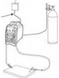
Diagram of a gas cylinder connected to a gas meter and cable, with an attached gas cylinder showing gas flow direction.- Set the switch (10) to TIC welding mode.
- Connect the return lead to the correct socket, marked with the number 5 on the diagram and tighten the locking nut.
-
Then remove the cap and connect the welding lead to the socket, marked with the number 6 on the diagram and tighten the locking nut. Connect the remaining leads to the socket marked with the number 7 on the diagram - control socket and to the socket market with the number 8 on the diagram - gas connection socket.
-
Then connect the gas source to the connector on the back of the machine.
- Once the machine is correctly assembled, connect the power lead and switch
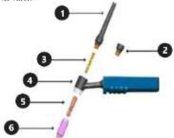
TIG Torch
text_image
Labeled diagram of a medical or laboratory device with numbered parts for identification- Cap, long
- Cap, short
- Collet
- Torch handle
- Collet inside housing
- Ceramic nozzle
MMA METHOD
- Turn the main switch on the front panel to „On“, the fan will start rotating.
- Make sure the TIG/ MMA switch is switched "down" to MMA. Pulse change switch and gas flow knob will not work.
- Set the welding current and make sure it is appropriate for the selected type of welding.
- Set the switch (10) to MMA welding mode.
- Connect the return lead to the correct socket, marked with the number 5 on the diagram and tighten the locking nut.
- Then connect the welding lead to the correct socket, marked with the number 6 on the diagram and tighten the locking nut.
ATTENTION: Polarization of the leads has to be different! All polarisation information should be shown on the packaging supplied by the electrode manufacturer.
- Once the machine is correctly assembled, connect the power lead and switch it on.
WARNING: during welding, it is forbidden to pull the plug or the cable that is being used. It may result in damage to the unit and/or risk of death.
Advice for use.
• The temperature of environment must not be higher than 40°C and the relative humidity should be less than 90%.
• Avoid welding in direct sunlight and/or rain.
- Do not use the machine in environments containing dust or corrosive gas.
• Avoid TIG welding in a strong wind.
- When the voltage, output current and machine temperature exceed the nominal values, the unit will automatically switch off. Current overload can cause damage and destroy the machine.
• After exceeding the operating cycle, the unit will stop working. When the main switch is in the "ON" position and the machine overloads, the overload indicator lights up (red LED). Do not pull the plug from the power supply so that the fan can cool the machine down. When the temperature drops, the overload indicator turns off and you can continue welding.
- DISPOSING OF PACKAGING
The various items used for packaging (cardboard, plastic straps, polyurethane foam) should be kept, so that the device can be sent back to the service centre in the best possible condition in case of any problems!
- TRANSPORTATION AND STORAGE
Shaking, crashing and turning upside down of the device should be prevented while it is transported. Store it in a properly ventilated surrounding with dry air and without any corrosive gas.
- CLEANING AND MAINTENANCE
- Disconnect from electricity when cleaning equipment
- Use cleaner without corrosive substances to clean surface.
- Dry all parts well after cleaning before the device is used again.
- Store the unit in a dry, cool location, free from moisture and direct exposure to sunlight.
• Regularly remove dust with dry and clean compressed air.
- REGULAR CONTROL OF THE DEVICE
Check regularly that the device doesn't present any damage. If there is any damage, please stop using the device. Please contact your customer service to solve the problem.
What to do in case of a problem?
Please contact your customer service and prepare following information:
• Invoice number and serial number (the latter is to be found on the technical plate on the device).
- If relevant, a picture of the damaged, broken or defective part.
- It will be easier for your customer service clerk to determine the source of the problem if you give a detailed and precise description of the matter. The more detailed your information, the better the customer service will be able to help you with your problem rapidly and efficiently!
CAUTION: Never open the device without the authorization of your customer service. This can lead to a loss of warranty!
PL PL
INSTRUKCJA OBSEUGI

BUTLA MOŻE WYBUCHNAĆ
text_image
Labeled diagram of a device with numbered parts for identificationL.p. Funkcja i opis
text_image
Diagram of a gas cylinder connected to a gas collection device with labeled componentstext_image
Labeled diagram of a desktop computer case with numbered parts for identificationP.C. Funkce a popis
natural_image
Simple line drawing of a gas cylinder connected to a gas washing bottle and a pressure vessel (no text or symbols)text_image
Labeled diagram of a computer control panel with numbered parts for identificationNr.
natural_image
Simple line drawing of a gas cylinder connected to a gas meter and tubing, with no text or symbols present.text_image
Labeled diagram of a soldering tool with numbered parts for identificationtext_image
Labeled diagram of a device with numbered parts for identificationnatural_image
Simple line drawing of a gas cylinder connected to a gas meter and power supply (no text or symbols)text_image
IMPUGNATURA TIG ① ② ③ ④ ⑤ ⑥text_image
Labeled diagram of a device with numbered parts for identificationtext_image
Diagram of a gas cylinder connected to a pressure vessel via tubing, with a gas cylinder and valve above.text_image
Labeled diagram of a medical or laboratory device with numbered componentstext_image
Labeled diagram of a device with numbered parts for identificationtext_image
Diagram of a gas cylinder connected to a digital measuring device with labeled components and connectionstext_image
Labeled diagram of a soldering tool with numbered parts for identification1 Lang haette, bagude
- Spændetang
natural_image
Simple line drawing of a handheld electronic device with wires and a power outlet (no text or symbols)NAMEPLATE TRANSLATIONS
| 1Importer: expondo Polska sp. z o.o. sp. k. ul. Nowy Kisielin-Innowacyjna 7, 66-002 Zielona Góra Poland, EU | STAMOS®WELDING GROUP | |||||||
| 2 Model: | ||||||||
| 1~f1f2 | EN60974-1expendo.de | |||||||
| MMA:10A/20.4V-180A/27.2V TIG:10A/10.4V-200A/18V | ||||||||
| ——— | X | 20% | 35% | 60% | 100% | |||
| U0V59V | I2 | MMA | TIG | MMA | TIG | MMA | TIG | |
| 180A | 200A | 103A | 152A | 80A | 118A | |||
| U2 | 27.2V | 18V | 24.1V | 16.1V | 23.2V | 14.7V | ||
| CE | Power Factor:0.7 | |||||||
| Insulation Class:F | U1V~230V | MMA Imax | 35.7A | TIG Imax | 26.5A | |||
| MMA Ieff | 16A | TIG Ieff | 15.7A | |||||
| 3Gas Cool | 50Hz | S1 | 8.2kVA | 6.1kVA | ||||
| IP21S | 4Production Year;5Serial No.: | |||||||
| 1234 | ● | ● | ● | ● | |
| DE | Importeur | Modell | Luftkühlung | Produktionsjahr | Ordnungsnummer |
| EN | Importer | Model | Gas Cool | Production Year | No. |
| PL | Importer | Model | Chłodzenie powietrzem | Rok produkcji | Numer serii |
| CZ | Dovazce | Model | Chlazení vzoluchem | Rok výroby | Sériové číslo |
| FR | Importateur | Modèle | Rcfroidissement à l'air | Année de production | Numéro de série |
| IT | Importatore | Modello | Raffreddamento ad aria | Anno di produzione | Numero di serie |
| ES | Importador | Modelo | Refrigeración por aire | Año de producción | Numero de serie |
WARNING LABEL TRANSLATIONS
For the disposal of the device please consider and act according to the national and local rules and regulations.
CONTACT
expondo Polska sp. z o.o. sp. k.