SPP32-025 - Water pump MSW - Free user manual and instructions
Find the device manual for free SPP32-025 MSW in PDF.

User questions about SPP32-025 MSW
0 question about this device. Answer the ones you know or ask your own.
Ask a new question about this device
Download the instructions for your Water pump in PDF format for free! Find your manual SPP32-025 - MSW and take your electronic device back in hand. On this page are published all the documents necessary for the use of your device. SPP32-025 by MSW.
USER MANUAL SPP32-025 MSW
1-Griffe
2- Pumpengehäuse
1- Gehäuse
2- Ein/Aus-Schalter
1- Schwarz
2- Blau
3- Braun
4- Gelb-Grün
This User Manual has been translated using machine translation. We have made every effort to ensure the translation is accurate, but please note that automated translations are not perfect and are not meant to replace human translators. The official version of the User Manual is in English. Any differences between the translated version and the original English are not legally binding. If you have any questions about the accuracy of the translation, please refer to the English version, which is the official reference. More language versions are available upon request via info@expondo.com.
Technical data
| Parameter description | Parameter value | ||||
| Product name | SUBMERSIBLE PUMP | ||||
| Model | |||||
| Rated voltage [V~/ Frequency [Hz] | 230/50 | ||||
| Rated power [W] | 1500 900 1500 1700 3000 | ||||
| Output power [W] | 750 370 750 1100 2200 | ||||
| Insulation class | |||||
| Working mode | |||||
| Protection class | |||||
| Protection rating IP | IP68 | ||||
| Dimensions [mm] | 830*90*90 710*92*92 1255*70*70 890*90*90 1330*90*90 | ||||
| Weight [kg] | 14.2 | 11 | 13.65 | 16.5 | 25.65 |
| Borewell diameter [mm] | 100 100 | 80 | 100 100 | ||
| H Max. [m] | 72 | 43 | 85 | 54 | 96 |
| Max. flow rate [L/min] | 100 100 | 63 | 180 180 | ||
| Max. sand content in water [%] | 0.25 | ||||
| Max. water temp. [°C] | 35 | ||||
| Max. depth under water surface [m] | 30 | ||||
| Max. number of starts/h | 50 | ||||
| Number of stages (impellers) | 10 | 6 | 24 | 8 | 14 |
| Outlet | 1.25" | 1.25" | 1.25" | 2" | 2" |
| Length of power cable [m] | 20 | ||||
| Max. water flow | 6 m3/h | 6000 l/h | 3.78 m3/h3780 l/h | 10.8 m3/h | 10.8 m | 3/h |
| Parameter description | Parameter value | ||||
| Product name | SUBMERSIBLE PUMP | ||||
| Model | MSW-SPP32-055 | MSW-SPP44-055 | MSW-SPP32-037 | MSW-SPP32-025 | MSW-SPP43-075 |
| Rated voltage [V~]/ Frequency [Hz] | 230/50 | ||||
| Rated power [W] | 1100 1100 | 900 750 1500 | |||
| Output power [W] | 550 550 | 370 250 750 | |||
| Insulation class | B | ||||
| Working mode | S1 | ||||
| Protection class | I | ||||
| Protection rating IP | IP68 | ||||
| Dimensions [mm] | 1033*71*71 | 750*90*90 | 806*70*70 | 680*70*70 | 850*90*90 |
| Weight [kg] | 11.15 | 13.05 | 10.1 | 8.75 | 14.5 |
| Borewell diameter [mm] | 80 100 | 80 80 100 | |||
| H Max. [m] | 60 | 58 | 39 | 28 | 91 |
| Max. flow rate [L/min] | 63 100 | 63 63 80 | |||
| Max. sand content in water [%] | 0.25 | ||||
| Max. water temp. [°C] | 35 | ||||
| Max. depth under water surface [m] | 30 | ||||
| Max. number of starts/h | 50 | ||||
| Number of stages (impellers) | 17 | 8 | 11 | 8 | 12 |
| Outlet | 1.25" | ||||
| Length of power cable [m] | 20 | ||||
| Max. water flow | 3.78 m3/h | 6 m3/h | 3.78 m3/h3780 l/h | 3.78 m3/h | 4.8 m3/h |
Head lift and water flow table
| MSW-SPP44-075 | Head lift [m] | 72 | 69 | 67 | 65 | 62 | 58 | 53 | 46 | 37 | 27 | 16 | |
| Water flow | m^3/h | 0 | 0.6 | 1.2 | 1.8 | 2.4 | 3.0 | 3.6 | 4.2 | 4.8 | 5.4 | 6.0 | |
| L/min | 0 | 10 | 20 | 30 | 40 | 50 | 60 | 70 | 80 | 90 | 100 | ||
| MSW-SPP44-037 | Head lift [m] | 43 | 42 | 40 | 39 | 37 | 35 | 32 | 27 | 22 | 16 | 9 | |
| Water flow | m^3/h | 0 0.6 | 1.2 | 1.8 2.4 | 3.0 | 3.6 4.2 | 4.8 | 5.4 6.0 | |||||
| L/min | 0 | 10 | 20 | 30 | 40 | 50 | 60 | 70 | 80 | 90 | 100 | ||
| MSW-SPP32-075 | Head lift [m] | 85 | 82 | 79 | 74 | 70 | 65 | 52 | 33 | 3 | |||
| Water flow | m^3/h | 0 | 0.5 | 1.0 | 1.5 | 1.8 | 2.0 | 2.5 | 3.0 | 3.78 | |||
| L/min | 0 8 17 | 25 30 | 33 42 | 50 63 | |||||||||
| MSW-SPP48-110 | Head lift [m] 54 | 52 51 | 48 45 | 43 37 | 32 22 | 12 | |||||||
| Water flow | m^3/h | 0 | 1.2 | 2.4 | 3.6 | 4.8 | 6.0 | 7.2 | 8.4 | 9.6 | 10.8 | ||
| L/min | 0 | 20 | 40 | 60 | 80 | 100 | 120 | 140 | 160 | 180 | |||
| MSW-SPP48-220 | Head lift [m] 96 | 92 89 | 85 80 | 74 66 | 54 38 | 21 | |||||||
| Water flow | m^3/h | 0 | 1.2 | 2.4 | 3.6 | 4.8 | 6.0 | 7.2 | 8.4 | 9.6 | 10.8 | ||
| L/min | 0 | 20 | 40 | 60 | 80 | 100 | 120 | 140 | 160 | 160 | 180 | ||
| MSW-SPP32-055· | Head lift [m] | 60 | 58 | 56 | 52 | 49 | 46 | 37 | 23 | 3 | |||
| Water flow | m^3/h | 0 | 0.5 | 1.0 | 1.5 | 1.8 | 2.0 | 2.5 | 3.0 | 3.78 | |||
| L/min | 0 8 17 | 25 30 | 33 42 | 50 63 | |||||||||
| MSw-SPP44-055 | Head lift [m] 58 | 56 54 | 52 50 | 47 42 | 36 29 | 21 | 12 | ||||||
| Water flow | m^3/h | 0 0.6 | 1.2 | 1.8 2.4 | 3.0 | 3.6 4.2 | 4.8 | 5.4 6.0 | |||||
| L/min | 0 | 10 | 20 | 30 | 40 | 50 | 60 | 70 | 80 | 90 | 10 | ||
| MSW-SPP32-037 | Head lift [m] | 39 | 37 | 36 | 34 | 32 | 30 | 24 | 15 | 2 | |||
| Water flow | m^3/h | 0 | 0.5 | 1.0 | 1.5 | 1.8 | 2.0 | 2.5 | 3.0 | 3.78 | |||
| L/min | 0 8 17 | 25 30 | 33 42 | 50 63 | |||||||||
| MSW-SPP32-025 | Head lift [m] | 28 | 27 | 26 | 25 | 23 | 22 | 17 | 11 | 1 | |||
| Water flow | m^3/h | 0 | 0.5 | 1.0 | 1.5 | 1.8 | 2.0 | 2.5 | 3.0 | 3.78 | |||
| L/min | 0 8 17 | 25 30 | 33 42 | 50 63 | |||||||||
| MSW-SPP13-075 | Head lift [m] 91 | 84 79 | 74 68 | 60 50 | 37 24 | ||||||||
| Water flow | m^3/h | 0 0.6 | 1.2 | 1.8 2.4 | 3.0 | 3.6 4.2 | 4.8 | ||||||
| L/min | 0 10 20 | 30 40 | 50 60 | 70 80 | |||||||||
General Description
The user manual is designed to assist in the safe and trouble-free use of the device. The product is designed and manufactured in accordance with strict technical guidelines, using state-of-the-art technologies and components. Additionally, it is produced in compliance with the most stringent quality standards.
DO NOT USE THE DEVICE UNLESS YOU HAVE THOROUGHLY READ AND UNDERSTOOD THIS USER MANUAL.
To increase the product life of the device and to ensure trouble-free operation, use it in accordance with this user manual and regularly perform maintenance tasks. The technical data and specifications in this user manual are up to date. The manufacturer reserves the right to make changes associated with quality
improvement. The device is designed to reduce noise emission risks to a minimum, taking into account technological progress and noise reduction opportunities.
Legend

The product satisfies the relevant safety standards.
Read instructions before use.
The product must be recycled.
WARNING! or CAUTION! or REMEMBER! Applicable to the given situation. (general warning sign)
ATTENTION! Electric shock warning!
Class I protection.
ATTENTION! The device mechanism may inflict serious injury or cause death.
PLEASE NOTE! Drawings in this manual are for illustration purposes only and in some details may differ from the actual product.
Usage Safety

ATTENTION! Read all safety warnings and all instructions. Failure to follow the warnings and instructions may result in an electric shock, fire and/or serious injury or even death.
The terms "device" or "product" are used in the warnings and instructions to refer to:
SUBMERSIBLE PUMP
Electrical safety
a) The plug must fit the socket. Do not modify the plug in any way. Using original plugs and matching sockets reduces the risk of electric shock.
b) Always use current sources that are connected to the ground and provide the necessary voltage (indicated on the label on the device).
c) Avoid touching earthed elements such as pipes, heaters, boilers and refrigerators. There is an increased risk of electric shock if the earthed device is exposed to rain, comes into direct contact with a wet surface or is operating in a damp environment. Water getting into the device increases the risk of damage to the device and of electric shock.
d) Do not touch the device with wet or damp hands.
e) Use the cable only for its designated use. Never use it to carry the device or to pull the plug out of a socket. Keep the cable away from heat sources, oil, sharp edges or moving parts. Damaged or tangled cables increase the risk of electric shock.
f) If working with the device outdoors, make sure to use an extension cord suitable for outdoor use. Using an extension cord suitable for outdoor use reduces the risk of electric shock.
g) Do not use the device if the power cord is damaged or shows obvious signs of wear. A damaged power cord should be replaced by a qualified electrician or the manufacturer's service centre.
h) Protect the unit from solar radiation. Use the device in a protected location to avoid damaging the equipment or endangering others.
i) Before cleaning, disconnect it from the power source. Use a soft damp cloth for cleaning. Avoid using detergents and make sure that no liquid enters the unit.
Safety in the workplace
a) Make sure the workplace is clean and well lit. A messy or poorly lit workplace may lead to accidents. Try to think ahead, observe what is going on and use common sense when working with the device.
b) Do not use the device in a potentially explosive environment, for example in the presence of flammable liquids, gases or dust. The device generates sparks which may ignite dust or fumes.
c) If you discover damage or irregular operation, immediately switch the device off and report it to a supervisor without delay.
d) If you are unsure about whether the product is operating correctly or if you find damage, please contact the manufacturer's service centre.
e) Only the manufacturer's service centre may make repairs to the product. Do not attempt to make repairs yourself!
f) In case of fire, use a powder or carbon dioxide (CO2) fire extinguisher (one intended for use on live electrical devices) to put it out.
g) Children or unauthorised persons are forbidden to enter a work station. (A distraction may result in loss of control over the device).
h) Regularly inspect the condition of the safety labels. If the labels are illegible, they must be replaced.
i) Please keep this manual available for future reference. If this device is passed on to a third party, the manual must be passed on with it.
j) Keep packaging elements and small assembly parts in a place not available to children.
k) Keep the device away from children and animals.
I) If this device is used together with another equipment, the remaining instructions for use shall also be followed.

REMEMBER! When using the device, protect children and other bystanders.
Personal safety
a) Do not use the device when tired, ill or under the influence of alcohol, narcotics or medication which can significantly impair the ability to operate the device.
b) The machine may be operated by physically fit persons who are able to handle the machine, are properly trained, who have reviewed this operating manual and have received training in occupational health and safety.
c) When working with the device, use common sense and stay alert. Temporary loss of concentration while using the device may lead to serious injuries.
d) To prevent the device from accidentally switching on, make sure the switch is on the OFF position before connecting to a power source.
e) Do not overestimate your abilities. When using the device, keep your balance and remain stable at all times. This will ensure better control over the device in unexpected situations.
f) The device is not a toy. Children must be supervised to ensure that they do not play with the device.
g) Do not put your hands or other items inside the device while it is in use!
Safe device use
a) Do not overload the device. Use the appropriate tools for the given task. A correctly-selected device will perform the task for which it was designed better and in a safer manner.
b) Do not use the device if the ON/OFF switch does not function properly (does not switch the device on and off). Devices which cannot be switched on and off using the ON/OFF switch are hazardous, should not be operated and must be repaired.
c) Make sure the plug is disconnected from the socket before attempting any adjustments, accessory replacements or before putting the device aside. Such precautions will reduce the risk of accidentally activating the device.
d) Disconnect the device from the power supply before commencement of adjustment, cleaning and maintenance. Such a preventive measure reduces the risk of accidental activation.
e) When not in use, store in a safe place, away from children and people not familiar with the device who have not read the user manual. The device may pose a hazard in the hands of inexperienced users.
f) Keep the device in perfect technical condition. Before each use check for general damage and especially check for cracked parts or elements and for any other conditions which may impact the safe operation of the device. If damage is discovered, hand over the device for repair before use.
g) Keep the device out of the reach of children.
h) Device repair or maintenance should be carried out by qualified persons, only using original spare parts. This will ensure safe use.
i) To ensure the operational integrity of the device, do not remove factory-fitted guards and do not loosen any screws.
j) When transporting and handling the device between the warehouse and the destination, observe the occupational health and safety principles for manual transport operations which apply in the country where the device will be used.
k) Avoid situations where the device stops working during use due to excessive loading. This may result in overheating of the drive elements and damage to the device.
I) Do not touch articulated parts or accessories unless the device has been disconnected from the power source.
m) Do not move, adjust or rotate the device in the course of work.
n) Clean the device regularly to prevent stubborn grime from accumulating.
o) The device is not a toy. Cleaning and maintenance may not be carried out by children without supervision by an adult person.
p) Do not run the device when empty.
q) It is forbidden to interfere with the structure of the device in order to change its parameters or technical condition.
r) Keep the device away from sources of fire and heat.
s) Do not overload the device.

ATTENTION! Despite the safe design of the device and its protective features, and despite the use of additional elements protecting the operator, there is still a slight risk of accident or injury when using the device. Stay alert and use common sense when using the device.
Use Guidelines
The product is designed for pumping clean water up to 35^ C from deep water wells.
The user is liable for any damage resulting from non-intended use of the device.
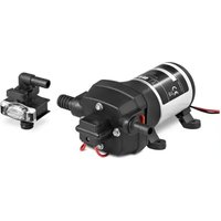
Device parts
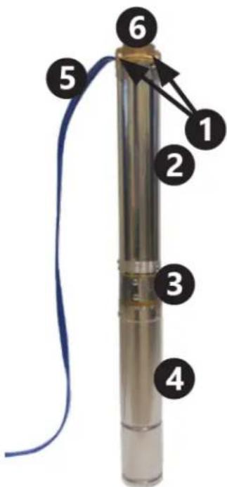
1- Handles
2- Pump housing
3- Water intake grille
4- Motor housing
5- Pump power cable
6- Water discharge opening
Control panel
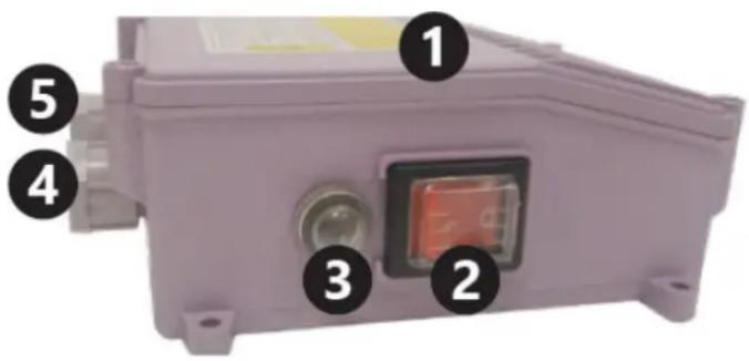
1- Housing
2- On/Off switch
3- Overcurrent circuit breaker
4- Pump power cable gland
5- Power cable gland
Before the first use
Upon receipt of the goods, check the packaging for integrity and open it. If the packaging is damaged, please contact your transport company and distributor within 3 days, and document the damages as detailed as possible. Do not turn the package upside down! When transporting the package, please ensure that it is kept horizontal and stable.
Disposing of packaging
Please keep all packaging materials (cardboard, plastic tapes and Styrofoam), so that in case of a problem, the device can be sent back to the service centre in accurate condition!
Device use

CAUTION! Failure to observe the following guidelines may lead to injury, constituting a risk to life and
health:
- Only a person with the appropriate qualifications and skills should put in place the electrical connections and install the pump.
- Connect the device power cable in accordance with the electrical diagram included in these instructions.
- The control panel should be located in a place protected against water ingress. Do not operate the device with wet hands.
- Extensions to the power lead, if required, should be hermetically sealed and performed by a person with appropriate qualifications.
-
Do not use the power cable to carry the device.
• The pump should be earthed. Use a residual current device up to 30mA in the electrical system. -
Disconnect from power source immediately if the pump malfunctions or the power cable insulation is damaged.
- Do not switch the pump on when standing in water or barefoot on a wet, electrically conductive surface.

Failure to observe the following guidelines may result in a device fault or sudden malfunction:
• Install the pump in a well in a vertical position.
• Before lowering the pump into a borewell, make sure the sludge has been cleaned out.
- Do not use the pump to pump dirty water (e.g. contaminated with oil, particles, abrasive particulate matter, etc.).
- Do not use the pump for salt water, corrosive
• substances, flammable liquids, etc.
- Do not use with water which exceeds 35^ .
- If the pump is installed in a borewell which is too wide, it will lead to insufficient cooling and the device will overheat. In this case, a cooling jacket should be installed.
- Do not start the pump before it is submerged in water. "Dry" operation results in permanent damage to the pump. The pump should be fully submerged, and the water surface should be at least 2 m above the water discharge holes.
- Attach the power cable to the delivery pipe (using cable ties for example) at least every 2 m to avoid the cable braking under its own weight.
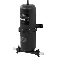
• Use a non-return valve to protect the pump against returning water impact.
- Before lowering the pump into a new borewell ensure sludge, silt and sand have been thoroughly cleaned out.
- Using the pump for pumping water with a high mineral content is not recommended. Water with a high mineral content may result in the appearance of deposits on the pump housing, preventing correct cooling of the motor which in turn might lead to overheating and damage the motor.
- Do not use the pump if the ambient temperature is below zero. Frozen water will damage the device and the water delivery system to the surface.
- Do not obstruct the water outlet when in use.
- Use a rope (standard nylon preferably) attached to the pump handles to lift, carry and lower the pump into a borewell.
- The product should be used under the supervision of a person with appropriate knowledge in terms of its use and operation.
Electrical wiring diagram
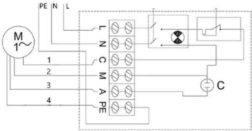
1- Black
2- Blue
3- Brown
4- Yellow-green
To switch on the pump set the On/Off switch to the On position.
If the overcurrent circuit breaker is tripped by a short circuit, overheating, etc., once the problem has been resolved (the cause of overcurrent circuit breaker tripping), release the circuit breaker by pressing the circuit breaker button on the control panel housing.
Dismantle the pump
In areas where temperatures drop below zero, dismantle the pump for the winter season and store it in accordance with the guidelines in “transport and storage” section.
To dismantle the pump:
- Set the On/Off switch to the Off ("0") position.
- Disconnect the pump from the power source.
• Extract the pump from the borewell using a steel or a different secure rope attached to the pump handles. - Disconnect the water delivery pipe from the pump.
• Empty any water remaining in the pump by turning it upside down. - Once the pump is dry, it is ready to be stored safely.
Transportation and Storage
- Shaking, crashing and turning the device upside down should be prevented when transporting it. Store it in a properly ventilated location with dry air and without any corrosive gas.
- Store the device in ambient temperatures above zero in a horizontal position. If the pump has been stored for more than a few days, ensure the device functions properly before installing it again.
Cleaning and Maintenance
• Always unplug the device before cleaning it.
• Use cleaner without corrosive substances to clean each surface.
• Clean organic deposits from the device after every use with a stream of clean water and a soft cloth.
- Store the unit in a dry, cool place, free from moisture and direct exposure to sunlight.
Regular control of the device
Check regularly if the device is damaged. In case of damage, please stop using it immediately and contact customer service for solving the problem.
What to do in case of a problem?
Please contact customer service and prepare the following information:
• Invoice number and serial number (the latter is to be found on the technical plate on the device).
• If necessary, take a picture of the damaged, broken or defective part.
- It will be easier for your customer service assistant to determine the source of the problem if you give a detailed and precise description of the problem. The more detailed your information, the better customer service will be able to solve your problem rapidly and efficiently!

CAUTION! Never open the device without the authorization of your customer service. This can lead to a loss of warranty!
Disposing of Used Devices
Do not dispose of this device in municipal waste systems. Hand it over to an electric and electrical device recycling and collection point. Check the symbol on the product, instruction manual and packaging. The plastics used to construct the device can be recycled in accordance with their markings. By choosing to recycle you are making a significant contribution to the protection of our environment. Contact local authorities for information on your local recycling facility.
Troubleshooting
| Problem | Possible | reason |
| The device does not start | Overcurrent circuit breaker has tripped | Remedy the cause of the circuit breaker tripping. Wait for the motor to cool down. Reset the circuit breaker to its original position. |
| No power | Make sure the power cable is connected properly. | |
| Damaged engine or power cable | Call your agent or qualified technician. | |
| Water feed clogged Remove the blockage. | ||
| The device starts but does not pump / pumps only a little water | Leaking water connections Seal the connections. | |
| Insufficient water level in the borewell | Check the water level. The pump should be at least 2 m below the water surface. | |
| Water delivery head too height | Install the pump in accordance with its technical specification. | |
1- Mieszkania
1- Czarny
2- Niebieski
3- Brązowy
4- Żółto-zielony
1- Bydlení
2- Vypínač zapnuto/vypnuto
1- Černá
2- Modrý
3- Hnědá
4- Žlutozelená
1- Logement
1- Noir
2- Bleu
3- Marron
4- Jaune-vert
1- Maniglie
2- Corpo pompa
1- Alloggiamento
1- Nero
2- Blu
3- Marrone
4- Giallo-verde
1- Alojamiento
1- Negro
2- Azul
3- Marrón
4- Amarillo-verde
1- Lakhatás
2- Be-/kikapcsoló
1- Fekete
2- Kék
3- Barna
4- Sárgászöld
1- Håndtag
2- Pumpehus
1- Boliger
2- Tænd-/slukknap
3- Overstrømsafbryder
1- Sort
2- Blå
3- Brun
4- Gul-grøn
1- Asuminen
2- On/Off-kytkin
1- Musta
2- Sininen
3- Ruskea
4- Keltainen-vihreä
1- Huisvesting
1- Zwart
2- Blauw
3- Bruin
4- Geelgroen
1- Bolig
2- På/av bryter
3- Overstrømsbryter
1- Svart
2- Blå
3- Brun
4- Gul-grønn
1- Handtag
2- Pumphus
3- Vattenintagsgaller
4- Motorhus
5- Pumpströmkabel
1- Hus
2- På/av-brytare
1- Svart
2- Blå
3- Brun
4- Gulgrön
1- Habitação
2- Interruptor liga/desliga
1- Preto
2- Azul
3- Martom
4- Amarelo-verde
1- Rukoväte
2- Puzdro čerpadla
1- Bývanie
1- Čierna
2- Modrá
3- Hnedá
4- Žlto-zelená
1-Жилища
1-черен
2- Синьо
3- кафяво
4-Жълто-зелено
1- Στέγαση
2- Διακόπτης On/Off
1- Μαύρος
2- Mπλε
3- Καστανός
4- Κιτρινοπράσινο
1- Kućište
1- Crna
2- Plava
3- Smeda
4- Žuto-zelena
1- Rankenos
2- Siurblio korpusas
3- Vandens paëmimo grotelës
4- Variklio korpusas
5- Siurblio maitinimo laidas
1- Büstas
2- Jjungimo/išjungimo jungiklis
1- Juoda
2- Mèlyna
3- Ruda
4- Geltona-žalia
1- Locuinte
1- Negru
2- Albastru
3- Maro
4- galben-verde
1- Ohišje
2- Modra
3- Rjava
4- Rumeno-zelena
For the disposal of the device please consider and act according to the national and local rules and regulations.
CONTACT
expondo Polska sp. z o.o. sp. k.