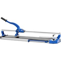
TCM800 - Saw MSW - Free user manual and instructions
Find the device manual for free TCM800 MSW in PDF.


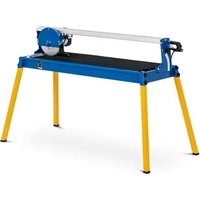
| Product type | Manual tile cutter |
| Brand | MSW |
| Model | TCM800 |
| Weight | 9.22 kg |
| Max cutting length | 800 mm |
| Max cutting thickness | 12 mm |
| Angle cut | No |
| Cutting material | Ceramic tile |
| Frame material | Steel / Aluminum |
| Number of guide rails | 2 |
| Blade type | Tungsten carbide wheel |
| Blade storage | Yes, in the handle |
| Cushion pads | Yes |
| Ergonomic handle | Yes |
| Cleaning | Soft cloth, no harsh chemicals |
| Maintenance | Grease the rails regularly |
| Safety | Safety goggles and gloves mandatory |
| Storage | In a dry place, out of reach of children |
| Usage | Flat and stable surface |
Frequently Asked Questions - TCM800 MSW
User questions about TCM800 MSW
0 question about this device. Answer the ones you know or ask your own.
Ask a new question about this device
Download the instructions for your Saw in PDF format for free! Find your manual TCM800 - MSW and take your electronic device back in hand. On this page are published all the documents necessary for the use of your device. TCM800 by MSW.
USER MANUAL TCM800 MSW
natural_image
Person installing or adjusting a mechanical component with a black handle (no visible text or symbols)Foto 1 Foto 2
natural_image
Close-up of a hand adjusting a mechanical device with a ruler and adjustment knob (no visible text or symbols)natural_image
Close-up of a mechanical assembly with a thin wire inserted into a component (no visible text or symbols)natural_image
Close-up of mechanical components on a tiled floor (no visible text or symbols)natural_image
Technical line drawing of a mechanical assembly with two arrows indicating direction (no text or symbols present)natural_image
Close-up of a mechanical device with a metallic ruler inserted, showing no visible text or symbols.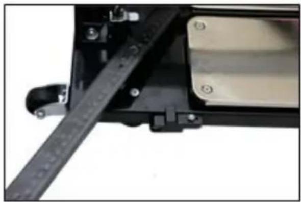
natural_image
Close-up of a mechanical assembly with a black metal rod and attached components (no visible text or symbols)natural_image
Technical line drawing of a mechanical assembly with no visible text or symbols| Description value | Parameter value | ||
| Product name | Manual tile cutter | ||
| Model | MSW-TCM1350-S | MSW-TCM1000-SM | MSW-TCM800-D |
| Weight [kg] | 28.5 | 22.5 | 15 |
| Maximum length of cut piece [mm] | 1350 1000 800 | ||
| Maximum thickness of cut piece [mm] | 18 16 14 | ||
| Possibility of cutting at an angle | YES YES YES | ||
| Maximum cutting angle [°] | 45 | 45 | 45 |
| Description value | Parameter value | ||
| Product name | Manual tile cutter | ||
| Model | MSW-TCM1000-D | MSW-TCM600 | MSW-TCM800 |
| Weight [kg] | 17.4 | 8.34 | 9.22 |
| Maximum length of cut piece [mm] | 1000 600 800 | ||
| Maximum thickness of cut piece [mm] | 14 12 12 | ||
| Possibility of cutting at an angle | YES NO NO | ||
| Maximum cutting angle [°] | 45 | - | - |
1. General overview
This manual is intended to assist you in safe and reliable use. The product is designed and manufactured strictly according to technical specifications using the latest technology and components, and maintaining the highest quality standards.
READ THE MANUAL CAREFULLY AND UNDERSTAND IT BEFORE USE.
To ensure long and reliable operation of the product, operate and maintain it correctly and strictly in compliance with this manual. The technical data and specifications in this manual are up-to-date. The manufacturer reserves the right to modifications for the purpose of quality improvement.
Explanation of symbols
 | Read the manual before use. |
 | CAUTION! or WARNING! or REMEMBER! indicates a specific instruction (general warning sign). |
 | Wear protective goggles. |
 | Wear protective gloves. |

CAUTION! The figures in this manual are illustrative only and may vary in some details from the actual appearance of the product.
The original version of the manual is in German language. Other language versions are translations from German.
2. Operating safety

CAUTION! Read all safety warnings and all instructions. Failure to follow the warnings and instructions may result in electric shock, fire and/or serious injury or death.
The term “equipment” or “product” in the warnings and instructions refers to the MANUAL TILE CUTTER.
a) Keep the workplace tidy and well lit. Disorder or poor lighting can lead to accidents. Be careful, watch what you are doing and use common sense when working with the appliance.
b) In the event of damage or malfunction of the appliance, turn it off immediately and report the incident to authorised personnel.
c) If in doubt as to whether the appliance is working, contact the manufacturer's technical service.
d) Repairs to the appliance may only be carried out by the manufacturer's service. Do not attempt to repair the product on your own!
e) No children or unauthorised individuals shall be allowed at the workplace. (Lack of attention may result in loss of control over the machine).
f) Use the appliance in a well-ventilated room.
g) Dust and debris are generated when the appliance is working. Protect bystanders from their harmful effects.
h) Keep this manual for future reference. If the product is to be handed over to a third party, hand it over with this user manual.
i) Keep packaging components and small installation parts out of the reach of children.
j) Keep the appliance away from children and animals.
k) Do not operate the product if you are tired, ill or under the influence of alcohol, drugs or medication which might significantly impair your ability to operate the product.
I) The product is not intended to be used by individuals (including children) with reduced mental, sensory or intellectual capacity or lack of experience and/or knowledge, unless they are supervised by an individual responsible for their safety or have been given instructions by the responsible individual on how to operate the product.
m) Be careful and use common sense when operating the product. Even a brief moment of distraction during operation may lead to serious injury.
n) Do not wear loose clothing or jewellery. Keep hair, clothing and gloves away from moving parts. Loose clothing, jewellery or long hair can be caught by moving parts.
o) The machine is not a toy. Children must be supervised to ensure that they do not play with it.
p) Do not overload the product. Use tools that are suitable for the application. A correctly selected product ensures better and safer performance of the work it is intended for.
q) Keep unused appliances out of the reach of children and anyone unfamiliar with the appliance or this manual. Appliances are dangerous in the hands of inexperienced users.
r) Keep the product in good working order. Before each use, check for generally evident damage and damage to any of the moving parts (inspect for cracks in parts and components or any other condition that may affect the safe operation of the product). If damaged, have the product repaired before use.
s) Keep the product out of the reach of children.
t) The product shall be repaired and maintained by qualified personnel using original spare parts only. This will ensure safe operation of the product.
u) To ensure the designed operational integrity of the product, do not remove the factory-installed covers or loosen any bolts.
v) When transporting and handling the appliance from storage to the place of use, follow the health and safety regulations for manual handling that apply in the country of operation of the appliance.
w) Clean the appliance regularly to prevent permanent deposits of dirt.
x) The machine is not a toy. Cleaning and maintenance shall not be performed by children without adult supervision.
y) Never attempt to tamper with the appliance to change its parameters or structure.
z) Keep the appliance away from sources of fire and heat.
aa) Beware of cutting elements! Potential for injury!

CAUTION!
Although the appliance has been designed to be safe and has been provided with adequate safeguards, and despite the use of additional safety measures, there is still a low, residual risk of accident or injury during its operation. Caution and common sense are advised when using the product.
3. Rules of use
The product is used for cutting ceramic tiles.
The user is responsible for any damage caused by non-intended use.
3.1. Appliance overview

- Cushioning pads
- Side supports
- Guide(s)
- Main handle
- Breaker unit
- Angle gauge
- Stopper
- Gauge screws
- Gauge lock
- Wheels
- Handle
- Storage for cutting blades
3.2. Preparations for operation
INSTALLING THE MACHINE
Products may require partial assembly. Components requiring assembly depend on the product model selected.
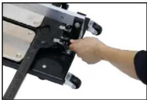
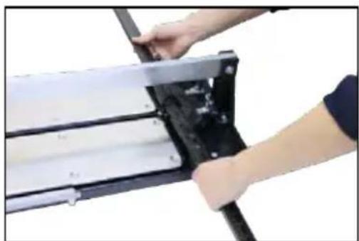
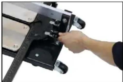
Angle gauge:
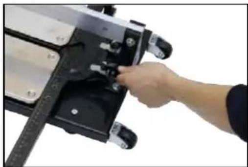
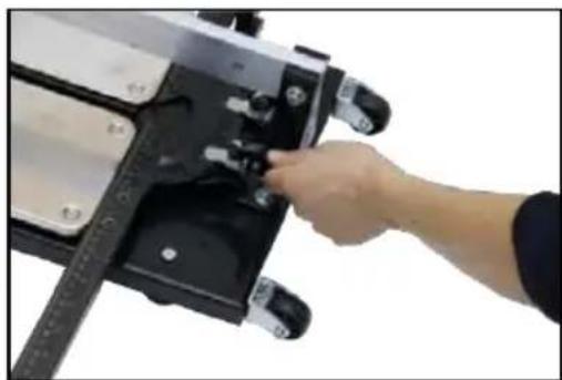
- place the angular gauge in the correct position (photo 1)
- tighten the screws (photo 2)
natural_image
Person assembling a mechanical component with visible internal structure (no text or symbols)Photo 1 Photo 2
natural_image
Close-up of a hand adjusting a mechanical device with a black handle and adjustment knob (no visible text or symbols)3.3. Operating the machine
- Nipper selection (for MSW- TCM1350-S)
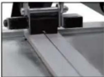
Work should begin by setting up the correct nipper. The MSW- TCM1350-S has two options depending on the thickness of the material to be cut:
- for tiles less than 10 mm thick it is recommended to use a small nipper,
natural_image
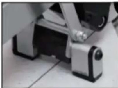
Close-up of a mechanical assembly with a metal bracket and angled component (no visible text or symbols)- For tiles thicker than 10mm it is recommended to use a larger nipper, for this purpose the feet of the larger nipper should be turned to the position shown in the picture below.
natural_image
Close-up of mechanical components on a tiled floor, no visible text or symbols2. Cutting a tile at right angle
- place the product on a straight and stable surface,
- make sure that the protractor on the gauge is set to "0". (for models MSW-TCM1350-S, MSW-TCM1000-SM, MSW-TCM800-D, MSW-TCM1000-D),
- place the tile on the cushioning pads and press against the gauge,
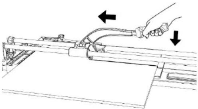
- use the handle to position the blade on the back edge of the tile,
- using moderate pressure, cut the tile in one continuous movement along its entire length,
natural_image
Line drawing of a mechanical assembly with two arrows indicating direction (no text or symbols)- lower the nipper,
- using the main handle, gently push the nipper away from the front edge of the tile,
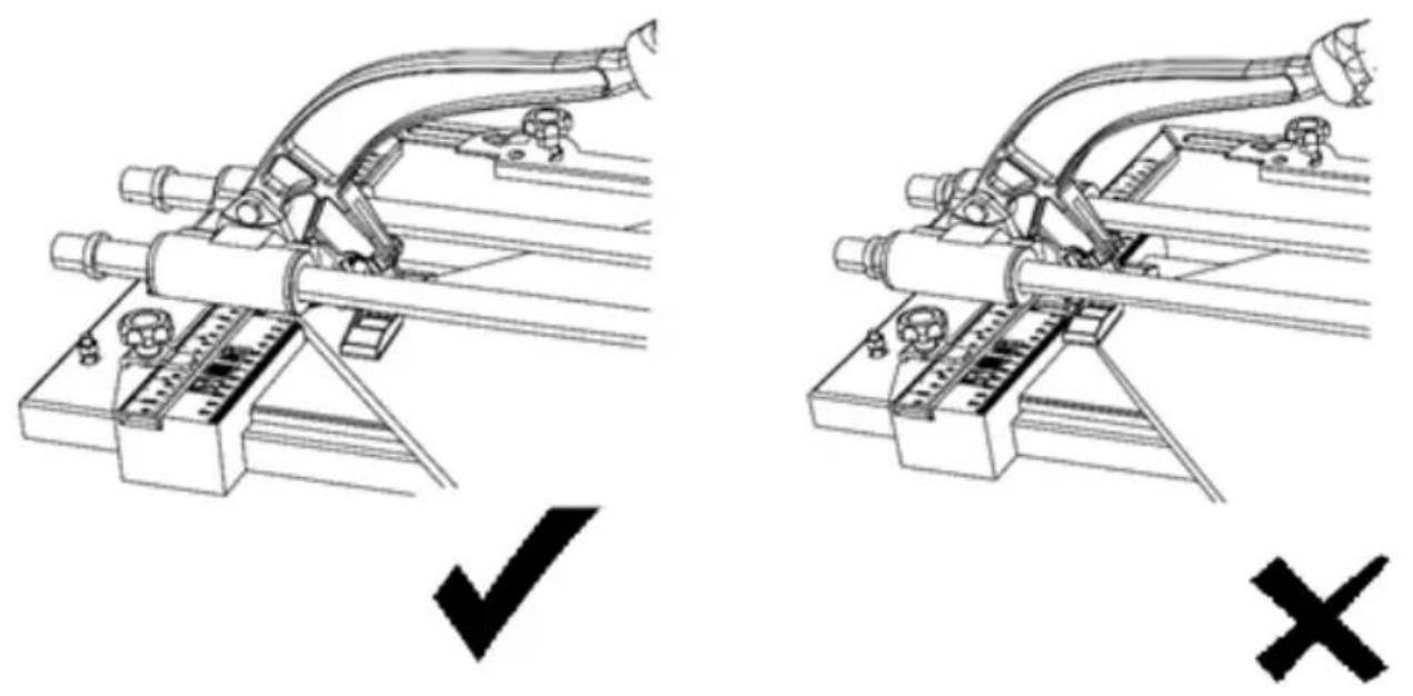
- press the handle until the tile breaks along the cut.
-
Cutting insert at different angles (for models MSW-TCM1350-S, MSW-TCM1000-SM, MSW-TCM800-D, MSW-TCM1000-D)
-
place the product on a straight and stable surface,
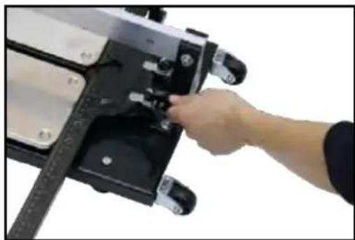
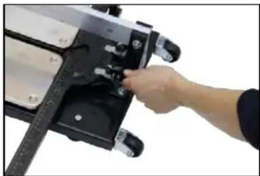
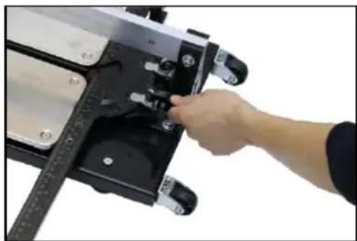
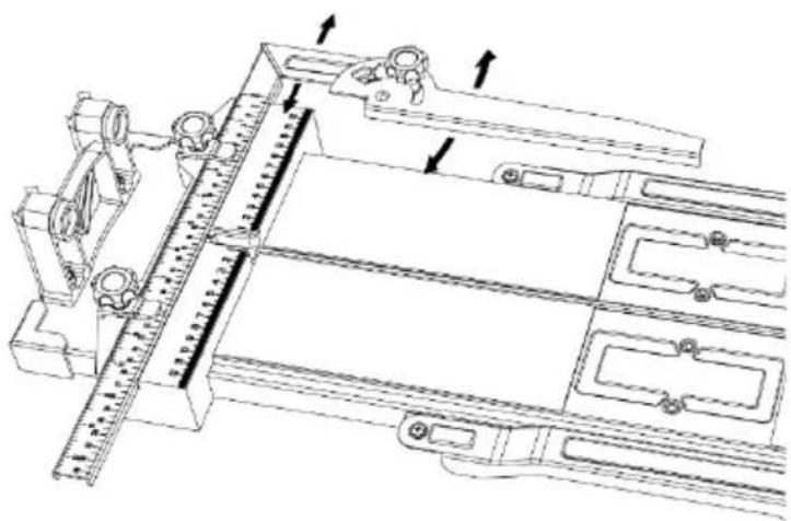
- loosen the bolts of the gauge and set it to the desired angle (the gauge can be freely rotated counterclockwise, to rotate it in the opposite direction, first press the lock shown in the photo below), place the stop on the gauge (for MSW-TCM1350-S, MSW-TCM1000-SM models),
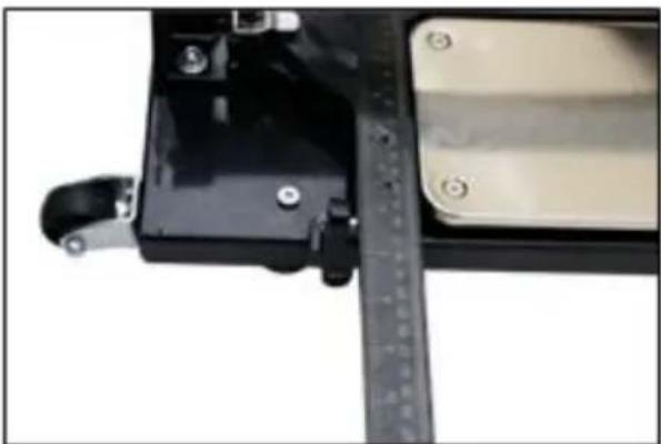
natural_image
Close-up of a mechanical device with a ruler inserted, showing no visible text or symbols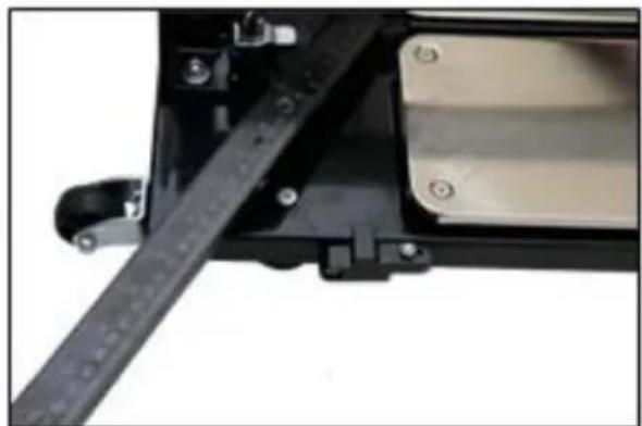
natural_image
Close-up of a mechanical device with a black metal strip and mounting bracket (no visible text or symbols)- loosen the gauge screws and set it in the right position according to the size of the tile, then loosen the gauge screw and set it at the right angle (for models MSW-TCM800-D, MSW-TCM1000-D),
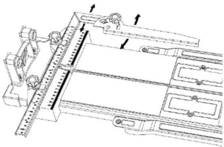
natural_image
Technical line drawing of a mechanical assembly with no visible text or symbols- tighten the screw and make sure again that the arrow points to the correct gauge setting,
- place the tile on the pads,
- set the stop and tighten the screw (for models MSW-TCM1350-S, MSW-TCM1000-SM),
- make the cut in the same way as the right-angle cut (described above).
Caution! Please note that the new cuts on the tiles have very sharp edges.
3.4. Cleaning and maintenance
a) Do not clean with any sharp and/or metal implements (e.g. a wire brush or a metal scraper) as these may damage the surface of the appliance.
b) Do not clean the appliance with acidic substances, medical products, thinners, fuel, oil or other chemicals as they may damage it.
c) When you have finished working, clean the machine by removing tile residue and dust.
d) Lubricate the guides regularly.
e) Store the device in a dry place. It is recommended to cover the device during storage.
f) Before each use, check that the device has all components and that they are working correctly.
Dane techniczne
natural_image
Person installing or adjusting a mechanical component with a tool (no visible text or symbols)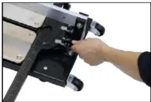
natural_image
Close-up of a hand adjusting a mechanical device with a ruler and adjustment knob (no visible text or symbols)Fot. 1 Fot.2
natural_image
Close-up of a mechanical assembly with a metal bracket and angled component (no visible text or symbols)natural_image
Close-up of mechanical components on a tiled floor, no visible text or symbolsnatural_image
Technical line drawing of a mechanical assembly with two hands operating a tool (no text or symbols present)natural_image
Technical line drawing of a mechanical assembly with pipes and a checkmark (no text or symbols)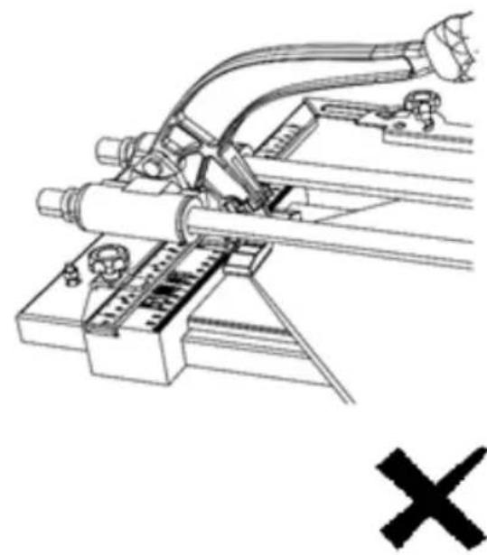
natural_image
Technical line drawing of a mechanical assembly with pipes and components (no text or symbols)natural_image
Close-up of a mechanical device with black components and a ruler inserted (no visible text or symbols)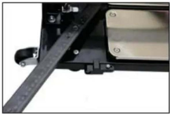
natural_image
Close-up of a mechanical assembly with a black metal frame and mounting bracket (no visible text or symbols)natural_image
Technical line drawing of a mechanical assembly with no visible text or symbolsnatural_image
Person assembling a mechanical component with a tool (no visible text or symbols)Fot. 1 Fot.2
natural_image
Hand operating a mechanical device with a black handle and control buttons (no visible text or symbols)natural_image
Close-up of a mechanical assembly with metal components and a thin rod (no visible text or symbols)natural_image
Close-up of mechanical components on a tiled floor (no visible text or symbols)natural_image
Technical line drawing of a mechanical assembly with two arrows indicating direction (no text or symbols present)natural_image
Close-up of a mechanical device with a ruler inserted, showing no visible text or symbols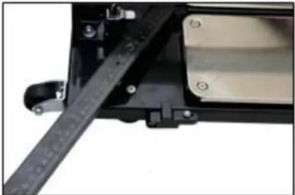
natural_image
Close-up of a mechanical device with a black metal strip and mounting bracket (no visible text or symbols)natural_image
Technical line drawing of a mechanical assembly with no visible text or symbolsnatural_image
Person installing or adjusting a mechanical component with a tool (no visible text or symbols)Photo 1 Photo 2
natural_image
Close-up of a hand adjusting a mechanical device with a ruler and adjustment knob (no visible text or symbols)natural_image
Close-up of a mechanical assembly with a metal bracket and a thin rod inserted into a white sheet (no visible text or symbols)natural_image
Close-up of mechanical components on a tiled floor, no visible text or symbolsnatural_image
Technical line drawing of a mechanical assembly with two arrows indicating direction (no text or symbols present)natural_image
Technical line drawing of mechanical assembly with two views (✓ and ✕) showing no text or symbolsnatural_image
Close-up of a mechanical device with a ruler and adjustment lever (no visible text or symbols)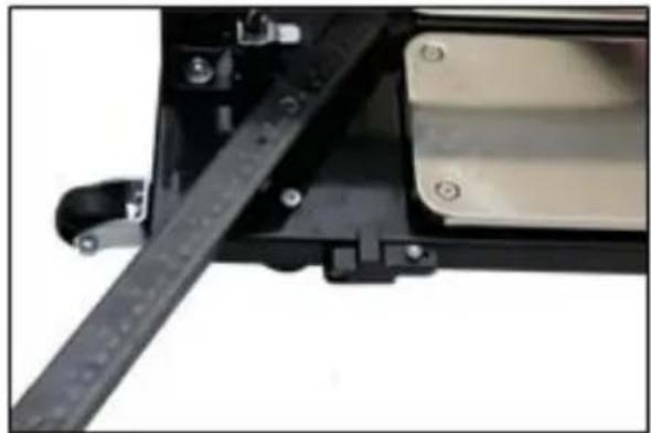
natural_image
Close-up of a mechanical device with a black rail and metallic components (no visible text or symbols)natural_image
Technical line drawing of a mechanical assembly with no visible text or symbolsnatural_image
Person installing or adjusting a mechanical component with a black rod (no visible text or symbols)Foto 1 Foto 2
natural_image
Close-up of a hand adjusting a mechanical device with a ruler and adjustment knob (no visible text or symbols)natural_image
Close-up of mechanical components with no visible text or symbolsnatural_image
Technical line drawing of a mechanical assembly with two arrows indicating direction (no text or symbols present)natural_image
Technical line drawing of a mechanical assembly with two views (✓ and ✕), no text or symbols present.natural_image
Close-up of a mechanical device with a ruler and adjustment lever (no visible text or symbols)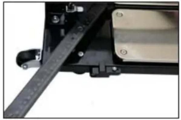
natural_image
Close-up of a mechanical assembly with a black metal frame and mounting bracket (no visible text or symbols)natural_image
Technical line drawing of a mechanical assembly with no visible text or symbolsnatural_image
Person installing or adjusting a mechanical component with a tool (no visible text or symbols)Foto 1 Foto 2
natural_image
Close-up of a hand adjusting a mechanical device with a ruler and adjustment knob (no visible text or symbols)natural_image
Close-up of a mechanical assembly with a metal bracket and a thin rod inserted into a white sheet (no visible text or symbols)natural_image
Close-up of mechanical components with no visible text or symbolsnatural_image
Technical line drawing of a mechanical assembly with two arrows indicating direction (no text or symbols present)natural_image
Technical line drawing of a mechanical assembly with two views (✓ and ✕), no text or symbols present.natural_image
Close-up of a mechanical device with a ruler and adjustment lever (no visible text or symbols)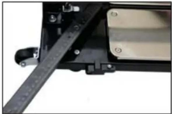
natural_image
Close-up of a mechanical device with a black rail and metallic components (no visible text or symbols)natural_image
Technical line drawing of a mechanical assembly with no visible text or symbolsnatural_image
Person installing or adjusting a mechanical component with a black frame (no visible text or symbols)-
fotó
-
fotó
natural_image
Hand operating a mechanical device with a black component and adjustment knobs (no visible text or symbols)natural_image
Close-up of mechanical components with no visible text or symbolsnatural_image
Technical line drawing of a mechanical assembly with two arrows indicating direction (no text or symbols present)natural_image
Technical line drawing of a mechanical assembly with pipes and a checkmark (no text or symbols)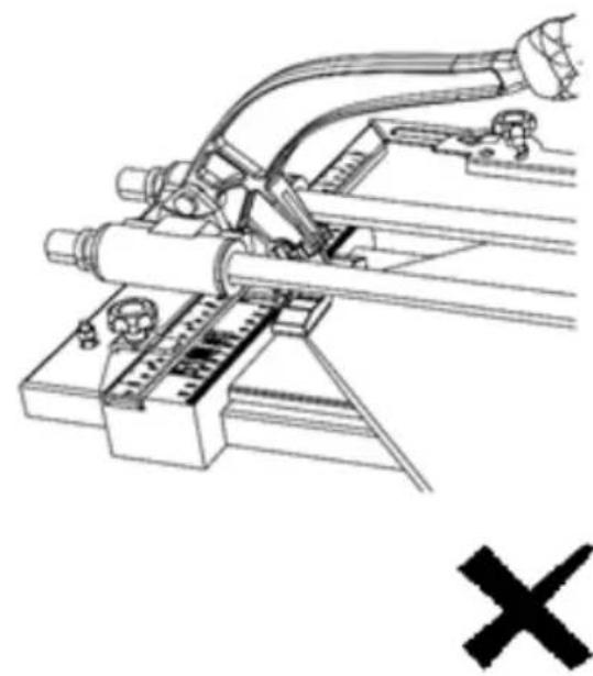
natural_image
Technical line drawing of a mechanical assembly with pipes and components (no text or symbols)natural_image
Close-up of a mechanical device with black components and a ruler inserted (no visible text or symbols)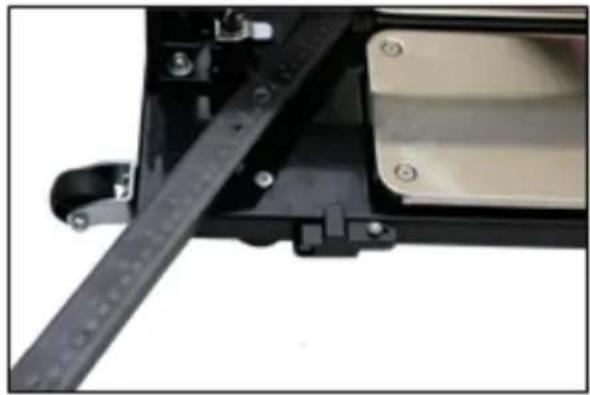
natural_image
Close-up of a mechanical device with a black metal bracket and mounting holes (no visible text or symbols)natural_image
Technical line drawing of a mechanical assembly with no visible text or symbols- Stødabsorberende puder
- Sidestøtte
- Skinne/r
- Hovedhåndtag
- Knuserenhed
- Vinkelmåler
- Stopper
- Skruer til måler
- Målerlås
- Hjul
- Håndtag
- Opbevaring af knive
natural_image
Close-up of a mechanical assembly with a rod inserted into a white sheet (no visible text or symbols)natural_image
Close-up of a mechanical device with black and silver components on a tiled floor (no visible text or symbols)natural_image
Technical line drawing of a mechanical assembly with two arrows indicating direction (no text or symbols present)natural_image
Technical line drawing of a mechanical assembly with pipes and a checkmark (no text or symbols)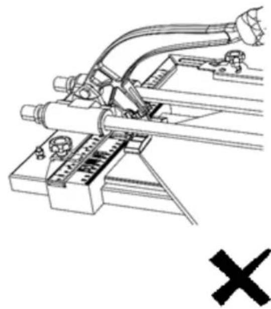
natural_image
Technical line drawing of a mechanical assembly with pipes and components (no text or symbols)natural_image
Close-up of a mechanical device with a ruler and adjustment knob (no visible text or symbols)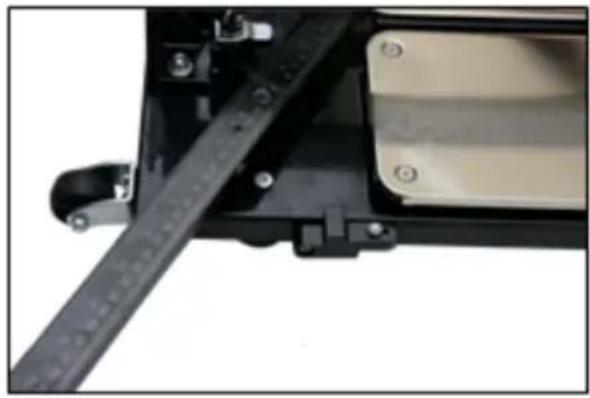
natural_image
Close-up of a mechanical device with a black lever and attached components (no visible text or symbols)-Løsn skruerne på måleren, og placer dem i henhold til flisens størrelse, løsn derefter vinkelmålerens skrue, og juster den til den korrekte vinkel (for MSW -TCM800-D, MSW-TCM1000-D),
natural_image
Technical line drawing of a mechanical assembly with no visible text or symbolsOUR CUSTOMERS' SATISFACTION IS OUR MAIN GOAL! PLEASE CONTACT US WITH QUESTIONS AT:
NASZYM GŁÓWNYM CELEM JEST SATYSFAKCJA KLIENTÓW W PRZYPADKU PYTAŃ PROSIMY O KONTAKT Z PRZEDSTAWICIELEM W DANYM KRAJU:
NOTRE BUT PREMIER EST VOTRE SATISFACTION! POUR TOUTE QUESTION, CONTACTEZ NOUS SUR:
NAŠÍM HLAVNÍM CÍLEM JE SPOKOJENOST NAŠICH ZÁKAZNÍKŮ! V PŘÍPADĚ OTÁZEK NÁS PROSÍM KONTAKTUJTE NA:
Brand : MSW
Model : TCM800
Category : Saw