S-LS-28 - Measuring equipment Stamos - Free user manual and instructions
Find the device manual for free S-LS-28 Stamos in PDF.

User questions about S-LS-28 Stamos
0 question about this device. Answer the ones you know or ask your own.
Ask a new question about this device
Download the instructions for your Measuring equipment in PDF format for free! Find your manual S-LS-28 - Stamos and take your electronic device back in hand. On this page are published all the documents necessary for the use of your device. S-LS-28 by Stamos.
USER MANUAL S-LS-28 Stamos
text_image
S-LS-30, S-LS-31, S-LS-32S-LS-30, S-LS-31, S-LS-32
This User Manual has been translated using machine translation. We have made every effort to ensure the translation is accurate, but please note that automated translations are not perfect and are not meant to replace human translators. The official version of the User Manual is in English. Any differences between the translated version and the original English are not legally binding. If you have any questions about the accuracy of the translation, please refer to the English version, which is the official reference. More language versions are available upon request via info@expondo.com.
Technical data
| Parameter description Parameter value | ||||
| Product name Laboratory power supply | ||||
| Model | S-LS-117 | S-LS-28 | S-LS-29 | S-LS-30 |
| Rated voltage [V~] / Frequency [Hz] | 230/50 | |||
| Rated power [W] 550 250 | ||||
| DC voltage adjustment range [V] | Channel I/II 0-30Channel III 5/3.3/2.5 | 0-30 | ||
| Current adjustment range [A] | Channel I/II 0÷5Channel III 3 | 0÷5 | ||
| Stabilization coefficient for operation under load | Channel I/II GV0.01% +5mV CC≤0.1% +10mAChannel III±50mV | CV ≤ 0.01% +2mV CC ≤ 0.1% +10mA | ||
| Operation stabilization coefficient | CV ≤ 0.01% +3mV CC ≤ 0.1% +3mA | |||
| Resolution | 10mV / 1mA | |||
| Parameter setting accuracy (25°C ±5°C) | Channel I/II≤0.5% +20mV≤0.5% +10mAChannel III:±50mV | ≤0.5% +20mV≤0.5% +10mA | ||
| Ripples | CV ≤ 2mVrms CC ≤ 3mArms | |||
| Temperature coef-ficient [ppm] | ≤150 | |||
| Response time for rise / fall of voltage / current intensity (at 10% load) [ms] | ≤100 | |||
| Load adjustment for parallel / series connection | ≤0.1% +0.1V /≤0.1% +0.1V | - | - | |
| Protections | OTP | OCP, OTP | OCP, OVP, OTP | |
| Fuse | T5A/250V | T3A/250V | ||
| Connection to a computer | USB,RS232 | - | USB,RS232 | - |
| Ambient temperature [°C] / Relative humidity [%] during use | 0÷40 / <80 | |||
| Ambient tempera-ture [°C] / Relative humidity [%] during storage | 10÷70 / <70 | |||
| Dimensions [mm] | 250x375x145 | 110x265x163 | 110x265x163 | |
| Weight [kg] | 10.5 | 4.5 | 4.32 | |
| Parameter description | Parameter value | |
| Product name Laboratory power supply | ||
| Model | S-LS-31 | S-LS-32 |
| Rated voltage [V~] / Frequency [Hz] | 230/50 | |
| Rated power [W] 250 500 | ||
| DC voltage adjustment range [V] | 0-30 | |
| Current adjustment range [A] | 0÷5 | 0÷10 |
| Stabilization coefficient for operation under load | CV ≤ 0.01%+2mVCC ≤ 0.1%+10mA | CV ≤ 0.01%+3mVCC ≤ 0.1%+20mA |
| Operation stabilization coefficient | CV ≤ 0.01% +3mV CC ≤ 0.1% +3mA | |
| Resolution 10mV / 1mA | ||
| Parameter setting accuracy (25°C ±5°C) | CV ≤ 0.5%+20mVCC ≤ 0.5%+10mA | CV ≤ 0.5%+20mVCC ≤ 0.5%+20mA |
| Ripples | CV ≤ 2mVrms CC ≤ 3mArms | CV ≤ 2mVrms CC ≤ 5mArms |
| Temperature coefficient [ppm] | ≤150 | |
| Response time for rise / fall of voltage / current intensity (at 10% load) [ms] | ≤100 | |
| Protections | OCP, OVP, OTP | OCP, OVP, OTP |
| Fuse | T3A/250V | T5A/250V |
| Connection to a computer | USB, RS232 | - |
| Ambient temperature [°C] / Relative humidity [%] during use | 0÷40 / <80 | |
| Ambient temperature [°C] / Relative humidity [%] during storage | 10÷70 / <70 | |
| Dimensions [mm] | 110x265x163 | 110x305x163 |
| Weight [kg] | 4.5 | 8.3 |
Note: Measurements of values shown in the Table were carried out at the ambient temperature of 25^ C ±5^ C, after device warm-up, i.e. 20 min of operation.
1. General description
The user manual is designed to assist in the safe and trouble-free use of the device. The product is designed and manufactured in accordance with strict technical guidelines, using state-of-the-art technologies and components. Additionally, it is produced in compliance with the most stringent quality standards.
DO NOT USE THE DEVICE UNLESS YOU HAVE THOROUGHLY READ AND UNDERSTOOD THIS USER MANUAL.
To increase the product life of the device and to ensure a trouble-free operation, use it in accordance with this user manual and regularly perform the maintenance tasks. The technical data and specifications in this user manual are up to date. The manufacturer reserves the right to make changes associated with quality improvement.

The product satisfies the relevant safety standards.

Read instructions before use.

The product must be recycled.

ATTENTION! Electric shock warning!

Only use indoors.

PLEASE NOTE! Drawings in this manual are for illustration purposes only and in some details may differ from the actual product.
2. Usage safety

ATTENTION!
Read all safety warnings and all instructions. Failure to follow the warnings and instructions may result in electric shock, fire and/or serious injury or even death.
Do not use in very humid environments or in the direct vicinity of water tanks. Prevent the device from getting wet. Risk of electric shock! Do not cover air inlets/outlets.
The terms "device" or "product" are used in the warnings and instructions to refer to:
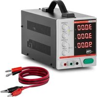
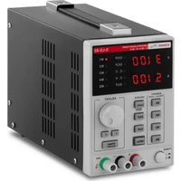
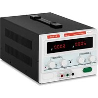
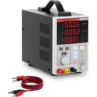
Laboratory power supply
2.1. Electrical safety
The plug has to fit the socket. Do not modify the plug in any way. Using original plugs and matching sockets reduces the risk of electric shock. Avoid touching earthed elements such as pipes, heaters, boilers and fridges. There is an increased risk of electric shock if the earthed device is exposed to rain, in direct contact with a wet surface, or operating in a humid environment. Water ingression into the device increases the risk of damage to the device and of electric shock. Do not touch the device with wet or damp hands. Use the cable only in accordance with its designated use. Never use it to carry the device or to pull the plug out of a socket. Keep the cable away from heat sources, oil, sharp edges or moving parts. Damaged or tangled cables increase the risk of electric shock.
2.2. Safety in the workplace
Make sure the workplace is orderly and well-lit. A messy or poorly lit workplace may lead to accidents. Try to anticipate what may happen, observe what is going on, and use common sense when working with the device. Do not use the device in an explosion hazard zone, for example in the presence of flammable liquids, gasses or dust. The device generates sparks which may ignite dust or fumes. Upon discovering damage or irregular operation, immediately switch the device off and report it to a supervisor without delay. Only the manufacturer's service point may repair the device. Do not attempt any repairs independently! If a fire starts, use solely powder or carbon dioxide (CO2) fire extinguishers suitable for use on live devices to put it out.

Remember! When using the device, protect children and other bystanders.
2.3. Personal safety
Do not use the device when tired, ill, or under the influence of alcohol, narcotics, or medication which can significantly impair the ability to operate the device. The device is not designed to be handled by persons (including children) with limited mental and sensory functions or persons lacking relevant experience and/or knowledge unless they are supervised by a person responsible for their safety or they have received instructions on how to operate the device. To prevent the device from accidentally switching on, make sure the switch is in the OFF position before connecting to a power source.
2.4. Safe device use
Do not use the device if the ON/OFF switch does not function properly (does not switch the device on and off). Devices that cannot be switched on and off using the ON/OFF switch are hazardous, should not be operated, and have to be repaired. When not in use, store it in a safe place, away from children and people not familiar with the device, who have not read the user manual. Use the device at an altitude not exceeding 2,000 m above sea level. Do not use the power supply under a maximum load for extended periods. Do not short live leads. Use larger cross-section leads for serial and parallel connections, to accommodate the achieved current and voltage. Disconnect external load leads before changing the power supply operating mode.

ATTENTION! Despite the safe design of the device and its protective features, and despite the use of additional elements protecting the operator, there is still a slight risk of accident or injury when using the device. Stay alert and use common sense when using the device.
3. Use guidelines
The product is used to supply direct current at a certain voltage to external devices.
The user is liable for any damage resulting from unintended use of the device.
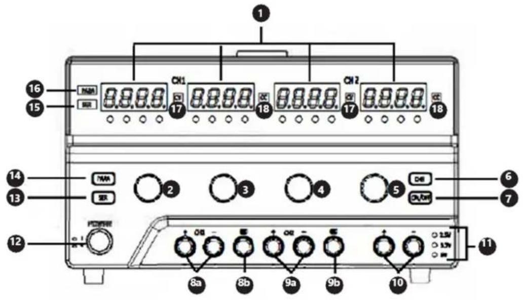
3.1. Device description
text_image
1 16 15 CN1 CN2 CN3 CN4 CN5 CN6 CN7 CN8 CN9 CN10 CN11 CN12 CN13 CN14 CN15 CN16 CN17 CN18 CN19 CN20 CN21 CN22 CN23 CN24 CN25 CN26 CN27 CN28 CN29 CN30 CN31 CN32 CN33 CN34 CN35 CN36 CN37 CN38 CN39 CN40 CN41 CN42 CN43 CN44 CN45 CN46 CN47 CN48 CN49 CN50 CN51 CN52 CN53 CN54 CN55 CN56 CN57 CN58 CN59 CN60 CN61 CN62 CN63 CN64 CN65 CN66 CN67 CN68 CN69 CN70 CN71 CN72 CN73 CN74 CN75 CN76 CN77 CN78 CN79 CN80S-LS-117, S-LS-28
text_image
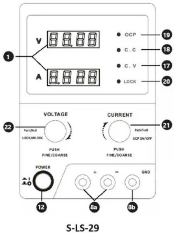
1 V A 8.8.8.8 OCP C.C C.V LOCK 19 18 17 20 22 VOLTAGE Push/hold LOCK/UNLOCK PUSH FINE/COARSE CURRENT Push/hold OCP ON/OFF 21 PUSH FINE/COARSE POWER 12 + - GND 8a 8b S-LS-29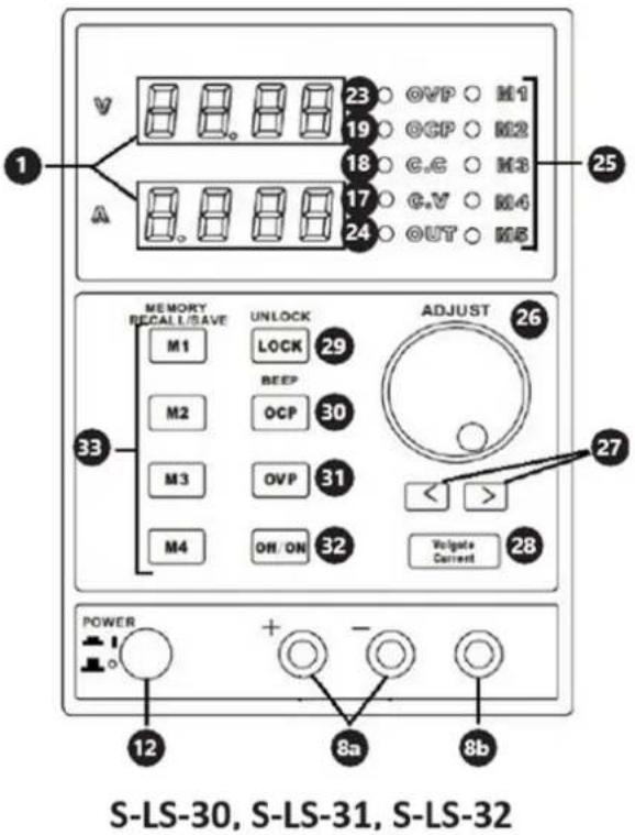
text_image
S-LS-30, S-LS-31, S-LS-321. Display
-
Knob to adjust voltage value for channel
-
Knob to adjust current intensity value for channel
-
Knob to adjust voltage value for channel II
-
Knob to adjust current intensity value for channel II
-
Button to choose voltage value for channel III
-
On/Off switch of outputs of channels I and II
-
a. (+) and (-) poles of channel
b. Earthing of channel I
- a. (+) and (-) poles of channel II
b. Earthing of channel II
-
a. (+) and (-) poles of channel III
-
LEDs - voltage value for channel III
-
Power supply On/Off switch
-
On/Off switch for series connection of channels
-
On/Off switch for parallel connection of channels
-
LED – series connection mode ON
-
LED - parallel connection mode ON
-
LED - constant value of output voltage
-
LED - constant value of output current intensity
-
LED – active overload protection
-
LED - active panel lock
-
Fine/coarse current intensity control knob / On/Off switch for overload protection
-
Fine/coarse voltage control knob / On/Off switch for setting lock
-
LED - active overvoltage protection
-
LED - active outputs
-
LED – memory indicator
-
Knob to control voltage and current intensity
-
Buttons to set positions on display
-
Voltage / Current intensity switch
-
On/Off switch for setting lock
-
On/Off switch for overvoltage protection / On/Off switch for sound signal
-
On/Off switch for overload protection
-
On/Off switch for outputs
-
Buttons for data storing / calling from memory
3.2. Preparing for use
Appliance location
The work surface where the device will be located must be suitable for the size of the appliance, please refer to the measurements. The work surface must be levelled, dry, heat-resistant, and at a fitting height from the ground to enable the proper use of the device. The power cord connected to the appliance must be properly grounded and correspond to the technical details!
3.3. Device use
S-LS-117. S-LS-28
Setting the output parameters
Channel 1/1push the knob (2-5) to adjust the chosen value and hold it down until the digit on the display starts flashing. Turn the knob to set the parameter. To set values for the next digits, repeat the activity described above.
Channel III: Push and hold down the button (6); the output voltage value will change in line with the following cycle: 2.5/3.3/5 [V] and the actual value will be indicated by one of the LEDs (11).
Parallel/series operation mode
To switch on any mode, push the button, (13) or (14), for the chosen mode and hold it down for 1 s; once the mode is activated, the suitable LED, (15) or (16), will light. The channel II is the master one in both connections. The connections in individual modes are as follows:
In series:
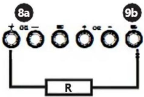
text_image
8a 0a + - R + - 0z - 9bIn parallel:
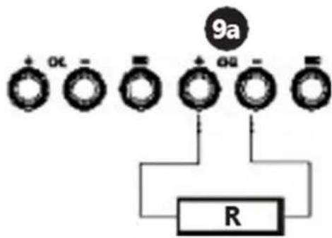
flowchart
graph TD
    A["9a"] --> B["+ OL ="]
    B --> C["+ Ω ="]
    C --> D["+ Ω ="]
    D --> E["R"]
Use the button (7) to switch the output voltage on and off.
S-LS-29
Setting the output parameters
There are 3 modes: modes 1 and 2 are used to load data manually, whereas mode 3 is used for computer-programmable settings.
Modes 1 and 2: to choose the mode, push the knob (21) or (22) respectively and hold it down for 2s.
- Mode 1: to change the voltage or current intensity value, push and hold down the knob until the indication on the suitable display starts flashing. Turn the knob (21) or (22) to set the output parameter value. The next pushing of the knob will change the resolution of the knob for adjustment of the voltage or current intensity value.
- Mode 2: to change the parameter values, turn the knobs (21) and (22) only; pushing the knobs will change the position to be edited on the display.
- Mode 3: push the knob (22) and hold it down for 3 s to lock the manual parameter setting modes; the power supply outputs are switched off and the knob (21) operates as the On/Off switch for the outputs (changes by pushing the knob) Connect the power supply to the computer and set the chosen parameters by means of the dedicated software. To exit from the mode 3, push the knob (22) and hold it down for 3s.
Overcurrent protection
To switch on the protection, push the knob (21) and hold it down for 3 s. If the outputs are switched off due to protection actuation, turn the knob (21) to reactivate the outputs. The OCP function needs to be switched on again.
Panel lock
Push the knob (22) and hold it down for about 2s. Repeat the above operation to unlock the panel.
S-LS-30, S-LS-31, S-LS-32
Setting the output parameters
Use the button (28) to choose the parameter to be entered. Set the parameter by turning the knob (26). By default, the coarse parameter control is set; to activate the fine control, push the knob (26).
Memory settings
The following settings are stored:
- Coarse/fine parameter adjustment mode
-
Switching on/off the sound signal
• Output voltage/current intensity -
Switching on/off the outputs
- Panel lock
The buttons (33) are used to save and recall the output parameter settings; during recalling the settings, the outputs are switched off automatically.
- Saving: push one of the buttons M1-M4 and hold it down until the respective LED (25) lights; the settings are saved. To save the 5th value, simultaneously press the "M4" button and adjust the "Adjust" k n o b .
- Recalling: Push the respective button M1-M4 to recall the saved settings. To restore the "M5" value, simultaneously press the "M button and the " " Robust
Overvoltage protection / Overload protection
To switch on and off the protections, use the respective buttons, (30) or (31). When the protection is active, the LED lights inform of this; whereas, after protection actuation, i.e. when the threshold values are exceeded, and the power supply of the outputs is cut off - the LED flashes. The next pushing of the protection On/Off button will reset the protection and restore the power supply for the outputs.
General
Software (this applies to models: S-LS-117, S-LS-29, S-LS-31)
• Install the software provided on the CD.
- Set the COM port in the computer: "Baud Rate: 9600 / Parity bit: None / Data bit: 8 / Stop bit: 1 / Data flow control: None".
- Connect the power supply to the computer by means of USB or RS232. The device should communicate with the computer automatically and the control panel of the device will be locked. The parameter edition will be possible only through the settings on the computer.
All models are equipped with thermal protection against overheating. In case of thermal protection actuation, any reason for the device overheating needs to be eliminated. Before restart, wait until the device cools down.
Fuse replacement: before replacement, disconnect the device from the power supply; eliminate the reason for the fuse blow and replace it with a new fuse of the same specification as indicated in the technical data table.
3.4. Cleaning and maintenance
Before each cleaning, adjustment, replacement of accessories, and if the device is not used, it is necessary to pull out the mains plug. Use cleaners without corrosive substances to clean each surface. Store the unit in a dry, cool place, free from moisture and direct exposure to sunlight. Never spray the device with water jets. Clean the vents with a paintbrush and compressed air. To ensure fire protection, replace the fuse only with the specified type and rating. To avoid electric shock, the power cord protective grounding conductor must be connected to the ground. Do not remove covers. Service maintenance should be provided by qualified personnel only.
DISPOSING OF USED DEVICES
Do not dispose of this device in municipal waste systems. Hand it over to an electric and electrical device recycling and collection point. Check the symbol on the product, instruction manual, and packaging. The plastics used to construct the device can be recycled in accordance with their markings. By choosing to recycle you are making a significant contribution to the protection of our environment.
Contact local authorities for information on your local recycling facility.

text_image
1 V A ● OCP ● C. C ● C. V ● LOCK 20 21 22 VOLTAGE Pash/hold LOCK/UNLOCK PUSH FINE/COARSE CURRENT Pash/hold OCP ON/OFF PUSH FINE/COARSE POWER 12 8a GND 8b S-LS-29
text_image
S-LS-30, S-LS-31, S-LS-32S-LS-30, S-LS-31, S-LS-32
text_image
S-LS-30, S-LS-31, S-LS-321. Displej
S-LS-30, S-LS-31, S-LS-32
Software (to platí pro modely: S-LS-117, S-LS-29, S-LS-31)
text_image
S-LS-30, S-LS-31, S-LS-32S-LS-30, S-LS-31, S-LS-32
text_image
1 V A ● OCP ● C. C ● C. V ● LOCK 20 21 22 VOLTAGE Pash/hold LOCK/UNLOCK PUSH FINE/COARSE CURRENT Pash/hold OCP ON/OFF PUSH FINE/COARSE POWER 12 8a GND 8b S-LS-29
text_image
S-LS-30, S-LS-31, S-LS-32S-LS-30, S-LS-31, S-LS-32
text_image
1 V A ● OCP ● C. C ● C. V ● LOCK 20 21 22 VOLTAGE Pash/hold LOCK/UNLOCK PUSH FINE/COARSE CURRENT Pash/hold OCP ON/OFF PUSH FINE/COARSE POWER 12 8a GND 8b S-LS-29
text_image
S-LS-30, S-LS-31, S-LS-32S-LS-30, S-LS-31, S-LS-32
text_image
S-LS-30, S-LS-31, S-LS-32chemical
Electrochemical reaction diagram showing two circular components labeled 8a and 9b connected to a resistor R with + and - chargesPárhuzamosan:
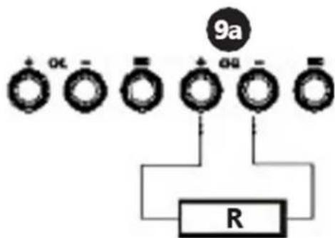
flowchart
graph TD
    A["9a"] --> B["+OL-"]
    A --> C["+Og-"]
    A --> D["+SO-"]
    B --> E["R"]
    C --> E
    D --> E
S-LS-30, S-LS-31, S-LS-32
text_image
1 V A ● OCP ● C. C ● C. V ● LOCK 20 21 22 VOLTAGE Pash/hold LOCK/UNLOCK PUSH FINE/COARSE CURRENT Pash/hold OCP ON/OFF PUSH FINE/COARSE POWER 12 8a GND 8b S-LS-29
text_image
S-LS-30, S-LS-31, S-LS-32S-LS-30, S-LS-31, S-LS-32
Indstilling af outputparametre
text_image
S-LS-30, S-LS-31, S-LS-321. Näyttö
S-LS-30, S-LS-31, S-LS-32
text_image
1 V A ● OCP ● C. C ● C. V ● LOCK 20 21 22 VOLTAGE Pash/hold LOCK/UNLOCK PUSH FINE/COARSE CURRENT Pash/hold OCP ON/OFF PUSH FINE/COARSE POWER 12 8a GND 8b S-LS-29
text_image
S-LS-30, S-LS-31, S-LS-32Overstroombeveiliging
S-LS-30, S-LS-31, S-LS-32
text_image
S-LS-30, S-LS-31, S-LS-321. Skjerm
S-LS-30, S-LS-31, S-LS-32
text_image
S-LS-30, S-LS-31, S-LS-321. Visning
S-LS-30, S-LS-31, S-LS-32
text_image
S-LS-30, S-LS-31, S-LS-32S-LS-30, S-LS-31, S-LS-32
text_image
S-LS-30, S-LS-31, S-LS-321. Displej
S-LS-30, S-LS-31, S-LS-32
text_image
S-LS-30, S-LS-31, S-LS-32S-LS-30, S-LS-31, S-LS-32
text_image
1 V A ● OCP ● C. C ● C. V ● LOCK 20 21 22 VOLTAGE Pash/hold LOCK/UNLOCK PUSH FINE/COARSE CURRENT Pash/hold OCP ON/OFF PUSH FINE/COARSE POWER 12 8a GND 8b S-LS-29
text_image
S-LS-30, S-LS-31, S-LS-32S-LS-30, S-LS-31, S-LS-32
text_image
S-LS-30, S-LS-31, S-LS-321. Prikaz
-
Gumb za podešavanje vrijednosti napona za kanal
-
Gumb za podešavanje trenutne vrijednosti intenziteta za kanal I
-
Gumb za podešavanje vrijednosti napona za kanal II
-
Gumb za podešavanje trenutne vrijednosti intenziteta za kanal II
-
Gumb za odabir vrijednosti napona za kanal III
-
Prekidač za uključivanje/isključivanje izlaza kanala I i II
-
a. (+) i (-) polovi kanala b. Uzemljenje kanala
-
a. (+) i (-) polovi kanala II b. Uzemljenje kanala II
-
a. (+) i (-) polovi kanala III
-
LED - vrijednost napona za kanal III
-
Prekidač za uključivanje/isključivanje napajanja
-
On/Off prekidač za serijsko spajanje kanala
-
On/Off prekidač za paralelno povezivanje kanala
-
LED – način serijskog spajanja ON
-
LED – uključen način rada paralelne veze
-
LED – konstantna vrijednost izlaznog napona
-
LED – konstantna vrijednost jakosti izlazne struje
-
LED – aktivna zaštita od preopterećenja
-
LED – aktivno zaključavanje ploče
-
Fini/grubi gumb za kontrolu intenziteta struje / On/Off prekidač za zaštitu od preopterećenja
-
Gumb za kontrolu finog/grubog napona / prekidač za uključivanje/isključivanje za zaključavanje postavki
-
LED – aktivna zaštita od prenapona
-
LED - aktivni izlazi
-
LED – indikator memorije
-
Gumb za kontrolu napona i jakosti struje
-
Gumbi za postavljanje položaja na zaslonu
-
Prekidač intenziteta napona / struje
-
Prekidač za uključivanje/isključivanje za zaključavanje postavki
-
On/Off prekidač za zaštitu od prenapona / On/Off prekidač za zvučni signal
-
Prekidač za uključivanje/isključivanje za zaštitu od preopterećenja
-
Prekidač za uključivanje/isključivanje izlaza
-
Tipke za pohranjivanje podataka / pozivanje iz memorije
3.2. Priprema za upotrebu
Mjesto uređaja
S-LS-30, S-LS-31, S-LS-32
Postavljanje izlaznih parametara
Tipkom (28) odaberite parametar koji želite unijeti. Postavite parametar okretanjem gumba (26). Prema zadanim postavkama postavljena je gruba kontrola parametara; za aktiviranje finog upravljanja pritisnite gumb (26).
Postavke memorije
text_image
S-LS-30, S-LS-31, S-LS-321. Ekranas
S-LS-30, S-LS-31, S-LS-32
Išvesties parametru nustatymas
text_image
1 V A ● OCP ● C. C ● C. V ● LOCK 20 21 22 VOLTAGE Pash/hold LOCK/UNLOCK PUSH FINE/COARSE CURRENT Pash/hold OCP ON/OFF PUSH FINE/COARSE POWER 12 8a GND 8b S-LS-29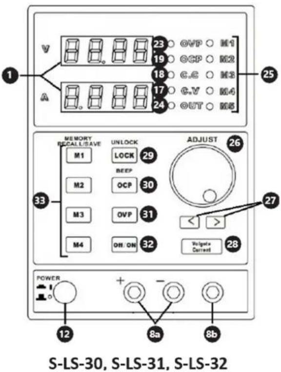
text_image
S-LS-30, S-LS-31, S-LS-32S-LS-30, S-LS-31, S-LS-32
Setarea parametrilor de ieşire
text_image
S-LS-30, S-LS-31, S-LS-321. Zaslon
S-LS-30, S-LS-31, S-LS-32
For the disposal of the device please consider and act according to the national and local rules and regulations.
CONTACT
expondo Polska sp. z o.o. sp. k.