S-LS-103 - Measuring equipment Stamos - Free user manual and instructions
Find the device manual for free S-LS-103 Stamos in PDF.

User questions about S-LS-103 Stamos
0 question about this device. Answer the ones you know or ask your own.
Ask a new question about this device
Download the instructions for your Measuring equipment in PDF format for free! Find your manual S-LS-103 - Stamos and take your electronic device back in hand. On this page are published all the documents necessary for the use of your device. S-LS-103 by Stamos.
USER MANUAL S-LS-103 Stamos
natural_image
Close-up of a black electronic device with a white number '3' on its side, placed on a surface (no visible text or symbols beyond the number)
text_image
STAMOS | oddning Laboratory Power Supply 30V 5A S-LS-96 2 c.v 30.00 v 4 1 c.c 5.000 A 5 150.0 w 6
text_image
RE C A L /SA V E M1 7 M2 8 M3 9 M4 10 ON OFF 19 Lock 11 OCP 12 OVP 13 OFF/ON 14 15 16 << >>> V/A 17 AD J U S T 20 21 22 GND +
text_image
23 485 24 230V 25 26 AC IN 27
natural_image
Two types of electrical probes with black and red wires, labeled 28 and 29 (no text or symbols on the cables themselves)- Baud rate: 9600
- Start bit: 1
- Data Bits: 8
- Check digit: None
- Stop bits: 1
- Data overflow control: None
Component 'MSComm32.ocx' or one of its dependencies not correctly registered: a file is missing or invalid
OK
text_image
Longwei numerical control power supply monitor interface Actual 00.00 V 00.00 V Setting output A 00.00 A 00.00 A output E OFF CC Output monitor start G H Set current J I Set voltage K L Instrument address: 1 N M Communication port Look for serial port Open serial port O P Output start Quit Q Copyright (C)2020, Longwei, ALL Rights ReservedLook for serial port
Output monitor start
text_image
Longwei numerical control power supply instrument address generator a Old instrument address: 0 2 Set new address of power supply b Communication port: Look for serial port Open serial port c Slave new address: 2 Quit d e f g h Copyright ©2020, Longwei, All Rights ReservedWo:
| Datenwortformat (serielle Daten) | 10-bit binary |
| Start bit | 1-bit |
| Data bit | 8-bit |
| Parity bit | None |
| Stop bit | 1-bit |
b) Kommunikationsdatenformat (Frames).
Slave address Function code Start address High 8 bits Low 8 bits Number of registers High 8 bits Low 8 bits CRC low 8 bits CRC high 8 bits
Address Function code Start address high bit Start address low 8 bits Data high 8 bits Data low 8 bits CRC 8 bits CRC high 8 bits 01 06 10 00 07 CF CF 6E
Address Function code Start address high bit Start address low 8 bits Data high 8 bits Data low 8 bits CRC low 8 bits CRC high 8 bits
01 06 10 00 07 CF CF 6E
| Description of the parameter | Value of the parameter | ||
| Product name | Laboratory power supply | ||
| Model | S-LS-96 | S-LS-100 | S-LS-101 |
| Supply voltage [V~] / Frequency [Hz] | 230/50 | ||
| Rated power [W]. | 150 | 300 | 300 |
| Voltage adjustment range DC [V] | 0-30 0-100 | 0-60 | |
| Electric current adjustment range [A] | 0-5 0-3 0-5 | ||
| Stabilization factor coefficient | CV≤0.2%+10mVCC≤0.2%+10mA | CV≤0.2%+10mVCC≤0.2%+10mA | CV≤0.2%+10mVCC≤0.2%+10mA |
| Stabilization factor coefficient under load (FS - full range) | CV≤0.25%FSCC≤0.25%FS | CV≤0.25%FSCC≤0.25%FS | CV≤0.25%FSCC≤0.25%FS |
| Pulse | CV≤50mVr.m.s.CC≤30mAr.m.s. | CV≤100mVr.m.s.CC≤30mAr.m.s. | CV≤70mVr.m.s.CC≤30mAr.m.s. |
| Resolution | 0.01 V/ 0.001 A | ||
| Safeguards | OCP, OVP, OTP, OPP | ||
| Connection to the computer | RS485 | ||
| Ambient temperature [°C]. / Relative humidity [%] during use | -10÷40 / < 80 | ||
| Ambient temperature [°C]. / Relative humidity [%] during storage | -40÷85 / < 80 | ||
| IP code | IP20 | ||
| Dimensions [Width x Depth x Height; mm] | 230x110x160 | 240x110x170 | 240x110x160 |
| Weight [kg] | 2 | 2 | 2 |
| Description of the parameter | Value of the parameter | |
| Product name | Laboratory power supply | |
| Model | S-LS-102 | S-LS-103 |
| Supply voltage [V~] / Frequency [Hz] | 230/50 | |
| Rated power [W]. | 180 | 300 |
| Voltage adjustment range DC [V] | 0-60 0-30 | |
| Electric current adjustment range [A] | 0-3 0-10 | |
| Stabilization factor coefficient | CV≤0.2%+10mVCC≤0.2%+10mA | CV≤0.2%+10mVCC≤0.2%+10mA |
| Stabilization factor coefficient under load (FS - full range) | CV≤0.25%FSCC≤0.25%FS | CV≤0.25%FSCC≤0.25%FS |
| Pulse | CV≤50mV r.m.s.CC≤30mA r.m.s. | CV≤50mV r.m.s.CC≤30mA r.m.s. |
| Resolution | 0.01 V/ 0.001 A | 0.01 V/ 0.01 A |
| Safeguards OCP, OVP, OTP, OPP | ||
| Connection to the computer | RS485 | |
| Ambient temperature [°C]. / Relative humidity [%] during use | -10÷40 / < 80 | |
| Ambient temperature [°C]. / Relative humidity [%] during storage | -40÷85 / < 80 | |
| IP code | IP20 | |
| Dimensions [Width x Depth x Height; mm] | 240x110x160 240x | 110x160 |
| Weight [kg] | 2 | 2 |
1. General Description
The instruction manual is intended to assist in safe and reliable use. The product is designed and manufactured strictly according to technical specifications using the latest technology and components and maintaining the highest quality standards.
PLEASE CAREFULLY READ AND UNDERSTAND THIS INSTRUCTION MANUAL BEFORE OPERATION,
To ensure long and reliable operation of the unit, make sure to operate and maintain it properly in accordance with the guidelines in this instruction manual. The technical data and specifications contained in this instruction manual are up to date. The manufacturer reserves the right to make changes in order to improve the quality. Taking the technical progress and the possibility of reducing noise into account, the unit is designed and built in such a way so that risks resulting from noise emissions are reduced to the lowest possible level.
Explanation of symbols
 | The product complies with applicable safety standards. |
 | Please read the instructions before use. |
 | Recyclable product. |
 | CAUTION! or WARNING! or REMINDER! describing a situation. (general warning sign). |
 | CAUTION! Warning of electric shock! |
 | For indoor use only. |

CAUTION! The illustrations in this instruction manual are for reference only and may differ from the actual product in some details.
The original instruction manual is in the German language version. Other language versions are translations from German.
2. Safety of use

CAUTION! Read all safety warnings and all instructions. Failure to follow the warnings and instructions may result in electric shock, fire and/or severe personal injury or death.
The term "unit" or "device" in the warnings and in the description of the instructions refers to the laboratory power supply.
2.1. Electrical safety
a) The plug of this unit must fit into the outlet. Do not modify the plug in any way. Original plugs and matching outlets reduce the risk of electric shock.
b) Avoid touching grounded parts, such as pipes, heaters, ovens, and refrigerators. There is an increased risk of electric shock if your body is grounded and touches the device exposed to direct rain, wet pavement, and operation in a humid environment. If water enters the device, there is an increased risk of damage to the device and electric shock.
c) Do not touch the unit with wet or damp hands.
d) Do not use the cord in an unintended manner. Never use it to carry the unit or to pull the plug out of the socket. Keep the cord away from heat sources, oil, sharp edges or moving parts. Damaged or tangled cords increase the risk of electric shock.
e) If you cannot avoid using the unit in a wet environment, use a residual current unit (RCD). Using an RCD reduces the risk of electric shock.
f) Do not use the unit if the power cord is damaged or shows signs of wear. A damaged power cord should be replaced by a qualified electrician or the manufacturer's service department.
g) To avoid electric shock, do not immerse the cable, plug, or unit itself in water or other liquid. Do not use the unit on wet surfaces.
h) CAUTION - THREAT TO LIFE! When cleaning or using the unit, never immerse it in water or other liquids.
i) Do not use the device in rooms with very high humidity / in the immediate vicinity of water tanks!
2.2. Safety in the workplace
a) Keep the work area tidy and well lit. Disorder or poor lighting can lead to accidents. Be foresighted, watch what you are doing and use common sense when using the unit.
b) Do not use the device in an explosive area, for example in the presence of flammable liquids, gases or dust.
c) If you find any damage or irregularities in the operation of the unit, immediately turn it off and report it to an authorized person.
d) If you have any doubts as to whether the unit is working properly or if it is damaged, contact the manufacturer's service department.
e) Only the manufacturer's service department can repair the unit. Do not carry out repairs yourself!
f) In case of open flames or fire, use only dry powder or snow (CO2) fire extinguishers to extinguish the live equipment.
g) No children or unauthorized persons are allowed in the work area. (Inattention may result in loss of control of the unit.)
h) Check the condition of the safety stickers regularly. Replace them if they are illegible.
i) Keep these instructions for use for future reference. If the unit is to be passed on to a third party, the operating instructions must also be handed over together with the unit.
j) Keep the packaging and small assembly parts out of the reach of children.
k) Keep the unit away from children and animals.
I) When using this unit together with other units, also follow the other instructions for use.
Please note! Keep children and other bystanders safe while operating the device.
2.3. Personal safety
a) Do not operate this unit if you are tired, ill or under the influence of alcohol, drugs or medication that could impair your ability to operate the unit.
b) The unit is not intended to be used by persons (including children) with reduced mental, sensory or intellectual functions or persons who lack experience and/or knowledge unless they are supervised or have been instructed by a person responsible for their safety on how to operate the unit.
c) The unit may be operated by persons who are physically fit, capable of operating it and appropriately trained, and who have read this instruction manual and have been trained in occupational safety and health.
d) Use caution and common sense when operating this device. A moment's inattention during operation may result in serious personal injury.
e) The unit is not a toy. Children should be watched to ensure that they do not play with the unit.
2.4. Safe use of the unit
a) Do not overload the unit. Use tools that are suitable for the application. A correctly selected unit will do a better and safer job for which it was designed.
b) Do not use the device if the ON/OFF switch does not function properly (does not turn on and off). Units that cannot be controlled by the switch are unsafe, cannot operate, and must be repaired.
c) Disconnect the unit from the power supply before adjusting, cleaning, or servicing. This precaution reduces the risk of accidental start-up.
d) Keep unused equipment out of the reach of children and out of the reach of anyone unfamiliar with the unit or this instruction manual. These units is dangerous in the hands of inexperienced users.
e) Keep the unit in good working condition. Check before each use for general damage or damage to moving parts (cracks in parts and components or any other condition that may affect the safe operation of the unit). If damaged, have the unit repaired before use.
f) Repairs and maintenance should be carried out by qualified personnel using only original spare parts. This will ensure the safety of use.
g) To ensure the designed operational integrity of the unit, do not remove factory-installed covers or loosen screws.
h) Do not move, shift, or rotate the machine while in operation.
i) Do not leave the unit switched on unattended.
j) Clean the unit regularly to prevent permanent dirt build-up.
k) The unit is not a toy. Cleaning and maintenance must not be performed by children without adult supervision.
I) Do not tamper with the unit to alter its performance or design.
m) Keep the unit away from sources of fire and heat.
n) Do not block the ventilation openings of the device!
o) Do not use the power supply under full load for a long time, it may cause damage to the device.
p) The output voltage of the Power Supply should not exceed the input voltage of the device being powered. Too high a voltage can damage the device.
q) Before changing the operation mode of the Power Supply, first disconnect the external load cables connected to it.
r) If the unit is operating with an inductive load such as magnetic coils, DC motors, stepper motors, etc., be sure to change the voltage/current slowly. NEVER turn the power on or off with an inductive load connected.
s) NEVER turn the power supply on or off with a load connected.
t) Do not short-circuit wires connected to the voltage.
u) Make sure that the input voltage matches the setting of the input voltage switch, otherwise it will cause the power supply to malfunction or even be damaged.

CAUTION! Although the product has been designed to be safe, with adequate safeguards, and despite the additional safety features provided to the user, there is still a slight risk of accident or injury when handling the unit. You are advised to use caution and common sense when using this product.
3. Rules of use
The unit is intended to supply external consumers with DC current of a specified voltage and amperage.
The user is responsible for any damage resulting from misuse.
3.1. Description
natural_image
Close-up of a black electronic device with a white number '3' on its side, placed on a surface (no visible text or symbols beyond the number)
text_image
STAMOS | oddning Laboratory Power Supply 30V 5A S-LS-96 2 c.v 30.00 v 4 1 c.c 5.000 A 5 150.0 w 6
text_image
RE C A L /SA V E M1 7 M2 8 M3 9 M4 10 ON OFF 19 Lock 11 OCP 12 OVP 13 OFF/ON 14 15 16 << >>> V/A 17 AD J U S T 20 21 22 GND +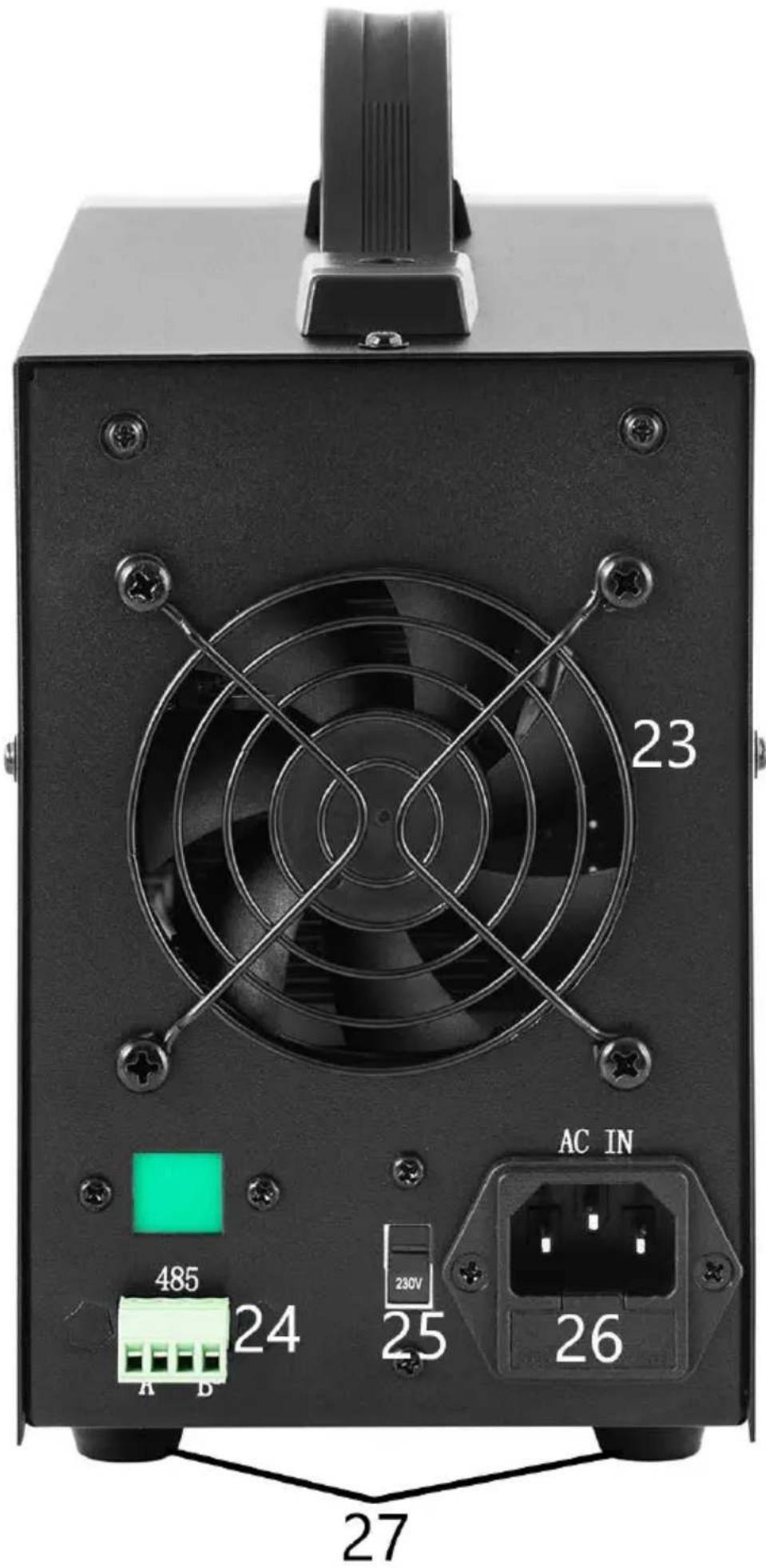
text_image
23 485 24 25 26 AC IN 27
natural_image
Two types of electrical probes with black and red wires, labeled 28 and 29 (no text or symbols on the cables themselves)- LED - indicator of operation in the output current stabilization mode
- LED - indicator of operation in the output voltage stabilization mode
- Handle
- Display of voltage values
- Current intensity display
- Output power display
7-10. Buttons for saving/recalling data from memory
- Lock button for locking the settings
- Overload protection ON/OFF button
- Over-voltage protection ON/OFF button
- Outputs OFF/ON button
- "to the left" button
- "to the right" button
- Voltage/current intensity switch
- Value adjustment knob
- Power ON/OFF button
- Output terminal - negative polarity
- Output terminal - ground
- Output terminal with positive polarity
- Fan
- RS 485 port
-
110/230V input voltage value switch
-
Power socket with fuse
- Feet
- Power cord
- Connection wires
3.2. Preparation for operation
POSITIONING OF THE UNIT
The ambient temperature must not exceed 40^ C and ambient humidity should not exceed 85%. Place the unit in a way that ensures good air circulation. Maintain a minimum clearance of 10 cm from any wall of the unit. Keep the unit away from any hot surfaces. Always operate the unit on a level, stable, clean, fireproof and dry surface and out of the reach of children and persons of impaired mental, sensory and intellectual functions. Place the unit in such a way that the mains plug can be reached at any time. Ensure that the power supply to the unit corresponds to that specified on the identification plate!
3.3. Working with the unit
To obtain the most stable settings within the tolerance of the PSU device, turn it on 30 minutes before starting work.
3.3.1. Operation
- Connect the power cord connector (28) to the socket (26) on the back of the unit and the plug to a power source.
- Switch on the device by pressing the ON/OFF button (19).
- Familiarize yourself with the parameters of the receiving device. Connect the external load to the terminals (20-22).
- Set the output parameters according to the instructions in sec. 3.3.2.
- Press the OFF/ON button (14) to activate the outputs. The button is illuminated when the outputs are active. Depending on the connected load, LED (1) or (2) will light up. Device b
- Press the OFF/ON button (14) again to turn off the power to the outputs.
The button's backlight will turn off. When the outputs are off, "OFF" is shown on the power value display (6).
- If the protection is triggered, the outputs will automatically be turned off.
- When you have finished using the unit, turn it off with the ON/OFF button (19), remove the external load, and unplug the unit from the power source.
3.3.2. Parameter settings
- Setting the voltage or current value
Press the "V/A" button (17) to select the output parameter to be edited.
Use the (15) and (16) buttons to set the cursor position to the position in the voltage/current value record to be changed (this sets the parameter adjustment accuracy between coarse and fine).
- Locking the settings
Press the "Lock" button (11) to lock the parameter editing.
The button will light up, the other buttons and the dial will be locked.
To unlock the editing, press the "Lock" button (11) again, the backlight will turn off and the functions of the other buttons will be restored.
- Audible signal
An audible alarm is given when overload or overvoltage protection is activated.
The audible alarm is factory set to on. To turn the alarm off/on again, press the knob (18).
- Saving / recalling settings
To save new settings press one of the M1-M4 buttons (7-10), the button will light up and the display will show the current voltage and current values.
At this point, enter the preferred voltage and current parameters following step 1 of the current subsection.
When the parameters on the display stop flashing, they are saved under the previously selected button.
Press one of the M1-M4 buttons (7-10) to recall the saved settings.
The selected button will light up and the screen will show the saved settings. At this point, you can activate the outputs using button (14).
3.3.3. Safeguards
- OCP (over current protection) - the safeguard is activated and deactivated with the "OCP" button (12).
When the protection is activated, the set current value is converted to the overcurrent protection value.
When the threshold value is exceeded the protection cuts off power to the outputs and the device emits a sound signal.
To reset the protection the user has to switch it off using the
button (12) and then on again.
- OVP (over voltage protection) - the protection is activated and deactivated with the "OVP" button (13).
When the protection is activated, the device automatically sets the threshold value (set voltage value + 0.5V) after exceeding which the protection is activated.
After exceeding the threshold value the power supply to the outputs is cut off and the device emits a sound signal.
To reset the protection the device must be switched off and then on again using the button (13).
- OTP (Over temperature protection) - safeguard against overheating.
3.3.4. Connecting the PSU to a computer
The device can be connected to a computer via a cable with an RS 485 connector. If the computer does not have such an input, a USB converter can be used.
To make a computer connect with the PSU, set the COM port by entering the following parameters:
- Baud rate: 9600
- Start bit: 1
- Data Bits: 8
- Check digit: None
- Stop bits: 1
- Data overflow control: None
When using USB to RS485 converter it is required to install the driver "CH340SER".
To start installation double-click the icon of CH340SER.exe application, confirm the installation and follow the instructions on the screen.
The driver installation file can be found on the manufacturer's store page.
For more information on RS485 and Modbus communication protocols, please refer to the following section.
3.3.5. Software
Caution: Installation files are available for download on the manufacturer's store page. On the website, locate the purchased product, then download the files to your computer and install them according to the instructions included in the further section.
- Installation of the PSU operating software
To be able to edit and read the parameters of the PSU after its connection to a computer, one needs to install a dedicated "Monitoring assistant" program for each model.
To install the program, double-click the icon assigned to it and follow the instructions displayed on the screen.
If instead of starting the installation process the screen displays the message as below:
POWER SUPPLY


Component 'MSComm32.ocx' or one of its dependencies not correctly registered: a file is missing or invalid
OK
This indicates that the MSComm32.ocx file necessary for the application to function properly is missing or corrupted.
Perform the following steps:
- determine how many bits of Windows are installed on the computer 32 or 64.
- copy the MSComm32.ocx file and paste it into the C:Windows32 folder for a 32-bit system and into the C:\Windows\sysWOW64 folder for a 64-bit system
- open the command line "cmd"
- at the command prompt, type depending on your system type: regsvr32 C:\Windows\system32\MSComm32.ocx
or: regsvr32 C:\Windows\sysWOW64\MSComm32.ocx
- Software interface description
text_image
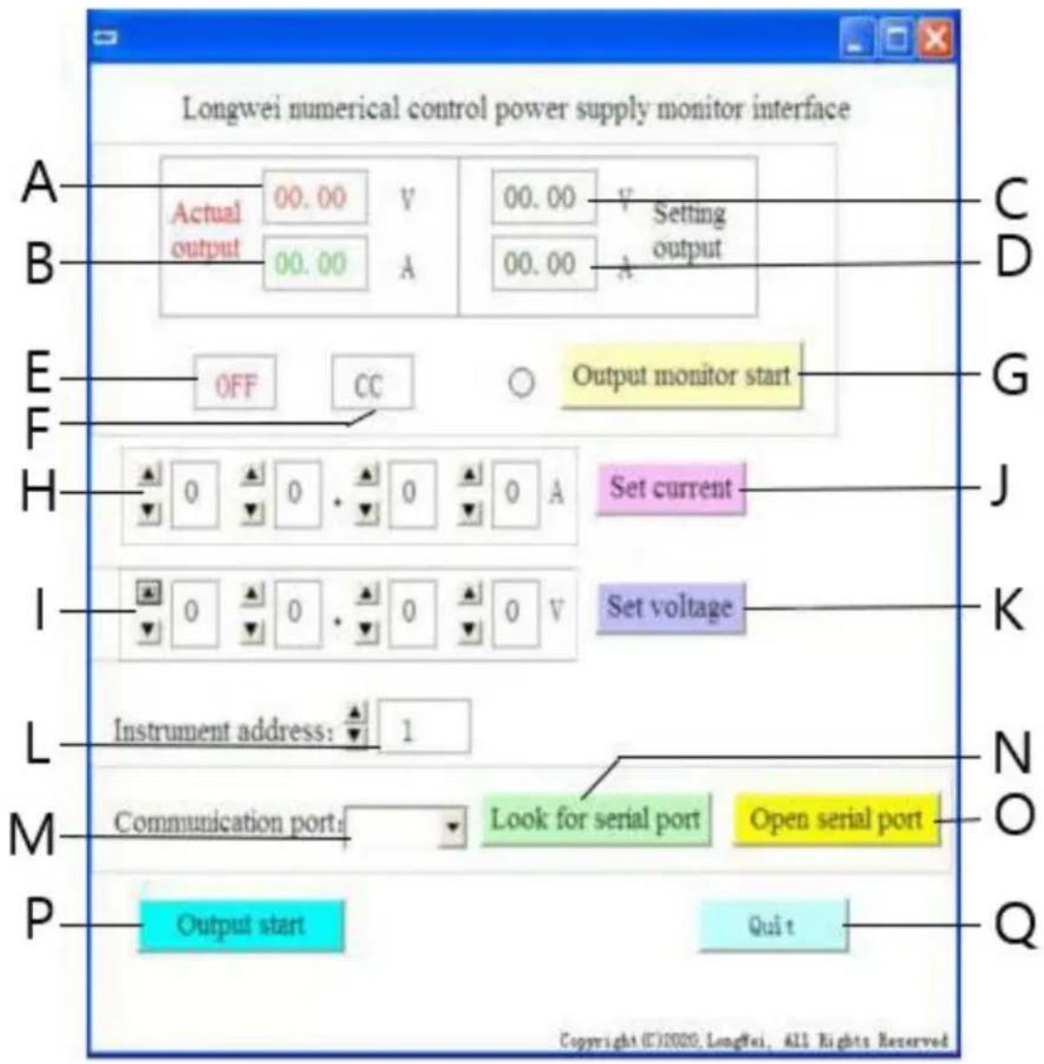
Longwei numerical control power supply monitor interface Actual 00.00 V 00.00 V Setting output output 00.00 A 00.00 A OFF CC Output monitor start Set current Set voltage Instrument address: 1 Communication port: Look for serial port Open serial port Output start Quit Copyright ©2020, Longwei, All Rights ReservedA. Current voltage value at the PSU output
B. Current value of the current at the PSU output
C. Set value of the voltage at the PSU output
D. Set value of the current at the output of the PSU
E. Current status of the PSU outputs: OFF - inactive outputs, ON - active outputs
F. Current status of the power supply: "CV" - voltage stabilization at the output, "CC" - current stabilization at the output.
G. Switch on/off button for output status monitoring
H. Fields for setting the values of the output current
I. Fields for setting the output voltage values
J. Button - Sending the entered current values to the PSU
K. Button - sending the entered voltage values to the PSU
L. Choice of the device number for RS 485 communication
M. Selection of the COM port number
N. Button for searching the port. Pressing the button will begin searching for available port numbers.
O. Button of opening the serial port and opening the communication port
P. Button for switching on/off the power supply outputs
Q. Button to turn off the software
- A detailed description of the buttons of the software interface
a)
Look for serial port
When clicked, the button will display a list of ports. If you do not know the number of the port to which the PSU has been connected, launch the system device manager.
Next, read the number assigned to the port where the PSU is connected and choose it from the drop-down list (M) to the left of the button.

USB-SERIAL CH341A (COM2)

b)
Open serial port
After pressing the button (if the correct port has been set in the previous step) the port connecting the computer with the device will be opened.
In the lower left corner of the software interface, "Port COMA is already open" will be displayed indicating success.
c)
Output start
If the port between the computer and the PSU is open, when the button is pressed, the power supply to the PSU's outputs will start. The button will change its name to "Output Stop". To stop the power supply to the outputs press the button again, then the power supply to the outputs will be cut off and the button will change its name back to "Output Start".
d)
Set voltage
In the Voltage (I) setting fields, set your preferred value by selecting numbers from the drop-down list.
To save the settings and send it to the PSU press the "Set voltage" button.
e)
Set current -
In the fields for setting the current value (H), set the preferred value by selecting from the drop-down list.
To save the settings and send it to the PSU press the "Set current" button.
f)
Output monitor start
After pressing the button, the fields concerning the current status of the PSU outputs will be updated, i.e. the value of voltage, current, operation mode, etc.
g)

Button for setting the device's address. By default, the device address is set to 1. However, if it is necessary to control a number of devices, an individual address should be set for each of them.
To do so, follow the steps below:
- start the "Instrument address generator" application (available for download on the expondo store page).
- After starting the application, the following window will appear.

text_image
Longwei numerical control power supply instrument address generator a Old instrument address: 0 2 Set new address of power supply b Communication port: Look for serial port Open serial port c Slave new address: 2 Quit d e f g h Copyright ©2020, Longwei, All Rights ReservedWhere,
a - current PSU address, set value 0
b - number of the COM port to which the PSU is connected to the computer.
Choose the number from the drop-down list.
c - the button of searching the port number (described in 3.3.5 sec. 2)
d - information about the newly set address of the PSU
e - new PSU address
f - the button of setting a new programmable PSU address
g - the button of opening the COM port
h - button of exiting the program.
3.3.6. Instructions for programming the Modbus and RS485 communication protocols
Caution: The device supports Modbus functions with the following codes: 03H, 06H, 10H and 01H (default setting).
1. Modbus RTU - frame structure
Message transmission must start with an interval of at least 3.5 characters.
The data frame must be a continuous stream of data transmission, if before the end of the frame there is a break longer than 3.5 characters, the receiving device refreshes the incomplete message and reads that the next byte is the beginning of a new message.
Similarly, if the gap between two separate messages is less than 3.5 characters, the receiving device will read the two messages as one.
The standard structure of an information frame is as follows:
| Beginning of the frame | Address | Function | Data | CRC control | Frame end |
| T1-T2-T3-T4 | 8 bites | 8 bites | N*8Bit | 16Bit | T1-T2-T3-T4 |
Description of the frame fields:
- Address - The master selects the slave by placing the address of the slave to connect to in the address field.
The address range for a single slave is 1...128 (decimal), the address is sent in hexadecimal format.
Address 0 is a Broadcast address, which is received and recognized by all slaves, but it is not possible to send a reply when a message is received.
- Function - The field encoding range is 1...255 (decimal). The function code informs the slave device what command to execute, e.g. read/write data of a registry group, etc.
- Data - this field contains additional information sent to the slave regarding the command sent in the function field, e.g. register addresses.
- CRC check - when CRC is generated, the younger byte is first and the older byte is second.
Caution: The interval between the communication frame response and the frame generated by the device when the communication rate is 9600 bps should be greater than 5ms.
| No. | Name | Description of the | Range | Number of decimal places | Read (w) and write (r) capabilities | Register address |
| 1 | Set-U | Voltage setting | 0-32.00 | 2 | w | 1000H |
| 2 | Set-I | Current settings | 0-10.50 | 2 | w | 1001H |
| 3 | U | Displays voltage value | 0-32.00 | 2 | r | 1002H |
| 4 | • I: | Displays the current value | 0-10.50 | 3 | r | 1003H |
| 5 | Run-Stop | Power output / stop status | 0.1 | 0 | r | 1004H |
| 6 | CC-CV-OC | Readout of voltage regulation and current flow status | 0,1,2 | 0 | r | 1005H |
| 7 | Set-Run-Stop | Power output/stop settings | 0.1 | 0 | w | 1006H |
| 8 | Set-Address | Setting the communication address value | 0-127 | 0 | w | 1008H |
| No. | Name | Description of the | Value of the | Description | Register address |
| 1 | Run-Stop | Power output / stop status | 0 | Stopped outputs | 1004H |
| 1 | Active outputs | ||||
| 2 | CC-CV-OC | Readout of voltage regulation and current flow status | 0 | Power supply in stabilization mode | 1005H |
| 1 | Power supply in regulation mode | ||||
| 2 | Power supply in overcurrent mode | ||||
| 3 | Set-Run-Stop | Power output/stop settings | 0 | Power off | 1006H |
| 1 | Power on |
Caution: When the communication address is 0x00H, it is a broadcast mode, i.e. all slaves can receive data, i.e. you can control data of many power supplies at one time.
2. Modbus RTU - communication protocol
a) Types and formats of communication data
The transmission of information is asynchronous and takes bytes as units.
The communication information transmitted between master and slave is in 10-bit word format:
| Word format (serial data) | 10-bit binary |
| Start bit | 1-bit |
| Data bit | 8-bit |
| Parity bit | None |
| Stop bit | 1-bit |
b) Communication data (frame) format.
| Data format | Address code | Function code | Data area | CRC control |
| Data length | 1-bit | 1-bit | N-bit | 16-bit CRC code (redundant cyclic code) |
c) Communication data transfer process
A command is sent by the master to the slave along with the address code. Only the slave with the address specified by the master can receive the command and read the information it contains.
If the CRC check passes correctly, the slave will execute the command and then send return data to the host. The information returned includes the address code, function code, data from the completed job, and CRC check
code. If the CRC check is incorrect, no information will be sent to the host.
d) Address code
The address code is the first byte (8 bits) of the information frame of each communication from 0 to 32. This byte indicates that the slave device set before the user will receive information from the master.
Each slave device must have a unique address code.
If the address code of the slave device matches the address code sent by the master device, the master device can read the command and send back a return message.
The address code sent by the slave to the master indicates the master's address, so that it can identify where the feedback is coming from.
e) Function code
The function code is sent in the second byte of the frame. The function codes that can be defined in the Modbus communication protocol are 1 to 127.
With the function code, the master device sends what task it wants the slave device to perform.
The response from the slave device returns the same function code, indicating that it has responded to the master device and performed the function-related operations.
The following table provides examples of Modbus protocol function codes.
| Function code | Definition | Operation (binary) |
| 03H | Reading data from a register | Read data from one or more registers |
| 06H | Write a single register | Write a set of data into a single register |
| 10H | Write multiple registers | Write multiple binary data sets to multiple registers |
f) Data area
The data area contains information about what should be returned from the slave or what actions should be performed.
The information can be data (digital inputs/outputs, analog inputs/outputs, registers, etc.), reference address, etc. E.g. the master sends the slave a command to return a register value (including the starting address and the length of the register to be read) via function code:
03, then the returned data includes both the length and data content of the register. For different slave devices, the address and data information are different.
The returned data includes: slave device address, function code, data area, and CRC code. The data in the data area is two bytes, with the first having higher priority.
g) Break time requirements
A data bus interrupt is required before data is sent, which must be greater than the baud rate (for 9600bps, the interrupt is min. 5ms).
- Introduction to Modbus protocol function codes
Caution: The power supply supports only the Modbus protocol function codes described below.
a) Function code "03": reading of multi-channel register inputs
E.g.: the master device needs to read data from 6 registers of the slave device whose address is 01 and start address is 1000.
The address and data of the slave's data register are:
| Register address | Data register (hexadecimal) | Corresponding parameters |
| 1000H | 0BB8 (3000) Set-U voltage multiplied by 100 | Set-U (30.00V) |
| 1001H | 03E8(1000) current Set-I multiplied by 100 | Set-I (10.00A) |
| 1002H | 0BB8(3000) voltage U times 100 | U(30.00V) |
| 1003H | 03E8(1000) current I multiplied by 100 | I(10.00A) |
| 1004H | 0001 (ON) – power supply on | Run-Stop (1) |
| 1005H | 0000 (CV) control status | CC0CV-OC (1) |
Note: the set voltage and current must be multiplied by 100 and then converted to hexadecimal notation before writing to the register.
E.g.. To set the voltage to 30.00V, multiply 30 by 100 to get 3000, then convert to hex to get 0BB8.
According to the above table, the value should be written to register 1000H.
The voltage and current value after reading from the register is again converted to decimal form and divided by 100.
E.g.. The value of reading register 1002H is 0BB7. After conversion, the actual voltage value is 29.99V.
Host - sending device
The format of the message sent by the host:
| Host message | Byte | Sent message | Remarks |
| Slave address | 1 | 01H | Send command to the slave with address 01H |
| Function code | 1 | 03H | Read registers |
| Start address | 2 | 1000H | Start address is 10000H |
| Register number | 2 | 0006H | Read 6 registers (12 bytes) |
| CRC code | 2 | C108 | CRC code caculated by the host |
Slave address Function code Start address High 8 bits Low 8 bits Number of registers High 8 bits Low 8 bits CRC low 8 bits CRC high 8 bits 01 03 10 00 00 06 C1 08
The format of the message sent back by the slave:
| Slave device response | Bit | Returned information | Remarks |
| Slave address | 1 | 01 | Information from the device with address 01 |
| Function code | 1 | 03 | Registers reading |
| Data length (bytes) | 1 | 0C | Total of 12 bytes |
| Data from 1 register | 2 | 0BB8(30.00V) | Contents of register 1000H |
| Data from register 2 | 2 | 03E8(10.00V) | Contents of register 1001H |
| Data from register 3 | 2 | 0BB8(30.00V) | Contents of register 1002H |
| Data from register 4 | 2 | 03E8(10.00A) | Contents of register 1003H |
| Data from register 5 | 2 | 0001 (ON) | Contents of register 1004H |
| Data from register 6 | 2 | 0001 (CV) | Contents of register 1005H |
| CRC code | 2 | DD9E | CRC code calculated by the slave |
Address Function code Data length Register 1 Register 2 Register 3
Register 4 Register 5 Register 6 CRC low 8 bits CRC high 8 bits
01 03 0C 0BB8 03E8 0BB8 03E8 0001 0001 DD 9E
Caution: In order to read the current and the voltage at the output from the power supply you need to read the data from two registers:
1002H and 1003H.
b) Function code "10H": write to multiple registers:
The host uses this function code to write multiple data in memory. A register in Modbus communication protocol refers to 16 bits (2 bytes), where the first bit is older.
For example, to set the voltage to 12.5V and the current to 5.5A, both values must be multiplied by 100, then converted to hexadecimal format and stored in registers 1000H and 1001H of the slave (the slave address code is 01).
Format of the message sent by the host:
| Message from host | Byte | Sent message | Remarks |
| Slave address | 1 | 01 | Send command to the slave with address 01H |
| Function code | 1 | 10 | Write multiple registers |
| Start address | 2 | 1000 | Starting address of the register to be recorded |
| Number of registers to be written | 2 | 0002 | Number of registers to be recorded |
| Number of data bytes to be written | 1 | 04 | Total number of data bytes stored (4 bytes) |
| Recorded data 1 | 2 | 04E2 (12.50V) | Data to be written to register 1000 |
| Recorded data 2 | 2 | 0226 (5.5.A) | Data to be written to register 1001 |
| CRC code | 2 | 1FD3 | CRC code calculated by the host |
Address Function code Start address Number of registers Total number of data bytes Save data 1 Save data 2 CRC low 8 bits CRC high 8 bits 01 10 1000 0002 04 04E2 0226 1F D3
The format of the message sent back by the slave:
| Slave device response | Bit | Sent message | Remarks |
| Slave address | 1 | 01 | Information from the device with address 01 |
| Function code | 1 | 10 | Records of multiple records |
| Start address | 2 | 1000 | Starting address of the register to be recorded |
| Number of registers to be written | 2 | 0002 | Number of written registers |
| CRC code | 2 | 4508 | CRC code calculated by the slave |
Slave address Function code Start address Number of registers CRC low 8 bits CRC high 8 bits
01 10 1000 0002 45 08
c) Function code '06H': write to single register
This function is used to save a fragment of data in the PSU memory. For instance, changing the voltage to 19.99V. After multiplying the value by 100 and converting it to hexadecimal format, it should be written to the slave register with address 1000H (the slave address code is 01).
Format of the message sent by the host:
Message from host Byte Sent message Remarks
| Slave address | 1 | 01 | Send command to the slave with address 01H |
| Function code | 1 | 06 | Register record |
| Start address | 2 | 1000 | Starting address of the register to be recorded |
| Recorded data | 2 | 07CF | Data to be written to register with address 1000 |
| CRC code | 2 | CF6E | CRC code calculated by the host |
Address Function code Start address high bit Start address low 8 bits Data high 8 bits Data low 8 bits CRC 8 bits CRC high 8 bits 01 06 10 00 07 CF CF 6E
The format of the message sent back by the slave:
| Slave device response | Bit | Sent message | Remarks |
| Slave address | 1 | 01 | Information from the device with address 01 |
| Function code | 1 | 06 | Records of multiple records |
| Start address | 2 | 1000 | Starting address of the register to be recorded |
| Recorded data | 2 | 07CF | Number of written registers |
| CRC code | 2 | CF6E | CRC code calculated by the slave |
Address Function code Start address high bit Start address low 8 bits Data high 8 bits Data low 8 bits CRC low 8 bits CRC high 8 bits
01 06 10 00 07 CF CF 6E
4. Error checking code (CRC check)
A master or slave can use the check code to verify the correctness of the received data.
Due to noise or other interference, errors can occur in the data transmission.
The error checking code (CRC) can be used to verify that the data transmission has proceeded correctly and allows erroneous data to be discarded, thus increasing security and system performance.
The CRC code in Modbus communications contains 2 bytes.
The younger 8 bits are in the front and the older 8 bits are in the back, resulting in a 16 bit binary number.
The CRC code is calculated by the sending device (host), it is in the last position in the information frame. The receiving device (slave) calculates the CRC code again and compares whether the designated and received codes are the same.
If the codes differ, an error has occurred during data transmission.
5. CRC code calculation method
The CRC calculation method is as follows:
a) A 16-bit register is set hexadecimal as FFFF. This register is called the CRC register.
b) Performing an XOR operation on the first byte of data (from the frame) and the younger byte of the CRC register.
The result of the operation is placed in the CRC register.
c) Shift the content of the CRC register one bit to the right (towards the younger bit), set the value of the oldest bit to 0, and then check the shifted bit.
d) If the output bit is 0, step (c) is repeated; if the bit is 1: the XOR operation of the CRC register with the polynomial A001 (1010 0000 0000 0001) is performed.
e) Repeat steps c) and d) up to eight times, which corresponds to processing 8 bits (1 byte) of data.
f) Perform steps b) through e) for the next byte of the communication frame.
g) After all bytes of the communication frame have been converted according to the above steps, the younger and older bytes of the resulting 16-bit CRC register are exchanged.
h) The final content of the CRC register is the value of the CRC code.
3.4. Cleaning and maintenance
a) Pull out the mains plug before each cleaning and when the device is not in use.
b) Use only non-corrosive cleaning agents for cleaning the surfaces.
c) After each cleaning, all the parts should be dried well before the unit is used again.
d) Store the unit in a dry and cool place protected from moisture and direct sunlight.
e) Do not spray the unit with a stream of water or immerse it in water.
f) Make sure that no water enters through the ventilation openings in the casing.
g) Clean the ventilation openings with a brush and compressed air.
h) Perform regular inspections of the unit checking technical fitness and any damages.
i) To ensure fire protection, replace the fuse only with the specified type and class.
Replacing the fuse
CAUTION! The fuse must be replaced by a specialist!
- Disconnect the device from the power supply.
- Disconnect the power cord and remove the fuse holder.
- Replace the fuse with a new one of the same rating.
- Reinstall the fuse holder.
CAUTION! To avoid damaging the fuse holder, do not use excessive force when removing and installing the fuse holder.
DISPOSAL OF USED UNITS.
At the end of its useful life, this product should not be disposed of with normal household waste but should be taken to a collection point for the recycling of electrical and electronic equipment. This is indicated by the symbol on the product, operating instructions or packaging. The materials used in this unit are recyclable according to their marking. You will be making an important contribution to protecting our environment by reusing, recycling or otherwise disposing of used units.
Your local administration will provide you with information about the appropriate disposal point for used units.
Dane techniczne
natural_image
Close-up of a black electronic device with a white number '3' on its side, placed on a surface (no visible text or symbols beyond the number)
text_image
STAMOS | oddning Laboratory Power Supply 30V 5A S-LS-96 2 c.v 30.00 v 4 1 c.c 5.000 A 5 150.0 w 6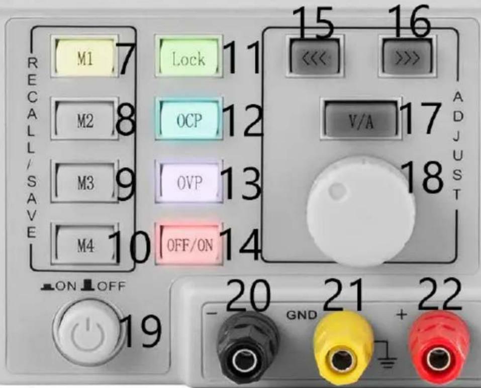
text_image
RECALL/SAVE M1 7 M2 8 M3 9 M4 10 ON OFF 19 Lock 11 OCP 12 OVP 13 OFF/ON 14 15 16 << >>> V/A 17 ADJUST 18 20 21 22 GND +
text_image
23 485 24 25 26 AC IN 27
natural_image
Two types of electrical probes with black and red wires, labeled 28 and 29 (no text or symbols on the cables themselves)- Baud rate: 9600
- Start bit: 1
- Data Bits: 8
- Check digit: None
- Stop bits: 1
- Data overflow control: None
Component 'MSComm32.ocx' or one of its dependencies not correctly registered: a file is missing or invalid
OK
text_image
Longwei numerical control power supply monitor interface Actual 00.00 V 00.00 V Setting output output 00.00 A 00.00 A OFF CC Output monitor start Set current Set voltage Instrument address: 1 Communication port: Look for serial port Open serial port Output start Quit Copyright ©2020, Longwei, All Rights ReservedLook for serial port
a)
Output monitor start
f)
text_image
Longwei numerical control power supply instrument address generator a Old instrument address: 0 2 Set new address of power supply b Communication port: Look for serial port Open serial port c Slave new address: 2 Quit d e f g h Copyright ©2020, Longwei, All Rights ReservedGdzie,
Slave address Function code Start address High 8 bits Low 8 bits Number of registers High 8 bits Low 8 bits CRC low 8 bits CRC high 8 bits 01 03 10 00 00 06 C1 08
Slave address Function code Start address Number of registers CRC low 8 bits CRC high 8 bits
01 10 1000 0002 45 08
Address Function code Start address high bit Start address low 8 bits Data high 8 bits Data low 8 bits CRC 8 bits CRC high 8 bits 01 06 10 00 07 CF CF 6E
Address Function code Start address high bit Start address low 8 bits Data high 8 bits Data low 8 bits CRC low 8 bits CRC high 8 bits
01 06 10 00 07 CF CF 6E
natural_image
Close-up of a black electronic device with a white number '3' on its side, placed on a surface (no visible text or symbols beyond the number)
text_image
STAMOS | oddning Laboratory Power Supply 30V 5A S-LS-96 2 c.v 30.00 v 4 1 c.c 5.000 A 5 150.0 w 6
text_image
RECALL/SAVE M1 7 M2 8 M3 9 M4 10 ON OFF 19 Lock 11 OCP 12 OVP 13 OFF/ON 14 15 16 << >>> V/A 17 ADJUST 18 20 21 22 GND +
text_image
23 485 24 25 26 AC IN 27
natural_image
Two types of electrical probes: a black cord with two terminal plugs and a red coiled wire, labeled 28 and 29 (no text or symbols on the cables themselves)- Baud rate: 9600
- Start bit: 1
- Data Bits: 8
- Check digit: None
- Stop bits: 1
- Data overflow control: None
Component 'MSComm32.ocx' or one of its dependencies not correctly registered: a file is missing or invalid
OK
text_image
Longwei numerical control power supply monitor interface Actual 00.00 V 00.00 V Setting output output 00.00 A 00.00 A OFF CC Output monitor start Set current Set voltage Instrument address: 1 Communication port Look for serial port Open serial port Output start Quit Copyright (C)2020, Longwei, All Rights ReservedLook for serial port
Output monitor start
Instrument address: ▲
text_image
Longwei numerical control power supply instrument address generator a Old instrument address: 0 2 Set new address of power supply b Communication port: Look for serial port Open serial port c Slave new address: 2 Quit d e f g h Copyright ©2020, Longwei, All Rights ReservedKde,
Slave address Function code Start address High 8 bits Low 8 bits Number of registers High 8 bits Low 8 bits CRC low 8 bits CRC high 8 bits 01 03 10 00 00 06 C1 08
Address Function code Start address high bit Start address low 8 bits Data high 8 bits Data low 8 bits CRC 8 bits CRC high 8 bits 01 06 10 00 07 CF CF 6E
Address Function code Start address high bit Start address low 8 bits Data high 8 bits Data low 8 bits CRC low 8 bits CRC high 8 bits
01 06 10 00 07 CF CF 6E
natural_image
Close-up of a black electronic device with a white number '3' on its side, placed on a surface (no visible text or symbols beyond the number)
text_image
STAMOS | oddning Laboratory Power Supply 30V 5A S-LS-96 2 c.v 30.00 v 4 1 c.c 5.000 A 5 150.0 w 6
text_image
RECALL/SAVE M1 7 M2 8 M3 9 M4 10 ON OFF 19 Lock 11 OCP 12 OVP 13 OFF/ON 14 15 16 << >>> V/A 17 ADJUST 18 20 21 22 GND +
text_image
23 485 24 25 26 AC IN 27
natural_image
Two types of electrical probes with black and red wires, labeled 28 and 29 (no text or symbols on the cables themselves)- Data overflow control: None
Component 'MSComm32.ocx' or one of its dependencies not correctly registered: a file is missing or invalid
OK
text_image
Longwei numerical control power supply monitor interface Actual 00.00 V 00.00 V Setting output output 00.00 A 00.00 A OFF CC Output monitor start Set current Set voltage Instrument address: 1 Communication port: Look for serial port Open serial port Output start Quit Copyright ©2020, Longwei, All Rights ReservedLook for serial port
a)
Output monitor start
text_image
Longwei numerical control power supply instrument address generator a Old instrument address: 0 2 Set new address of power supply b Communication port: Look for serial port Open serial port c Slave new address: 2 Quit d e f g h Copyright (E)2020. Longwei, All Rights ReservedOù :
Slave address Function code Start address High 8 bits Low 8 bits Number
of registers High 8 bits Low 8 bits CRC low 8 bits CRC high 8 bits 01 03 10 00 00 06 C1 08
Slave address Function code Start address Number of registers CRC low 8 bits CRC high 8 bits
01 10 1000 0002 45 08
Address Function code Start address high bit Start address low 8 bits Data high 8 bits Data low 8 bits CRC 8 bits CRC high 8 bits 01 06 10 00 07 CF CF 6E
Address Function code Start address high bit Start address low 8 bits Data high 8 bits Data low 8 bits CRC low 8 bits CRC high 8 bits
01 06 10 00 07 CF CF 6E
natural_image
Close-up of a black electronic device with ventilation grilles and a number '3' on the side (no readable text or symbols beyond the number)
text_image
STAMOS | oddning Laboratory Power Supply 30V 5A S-LS-96 2 c.v 30.00 v 4 1 c.c 5.000 A 5 150.0 w 6
text_image
RECALL/SAVE M1 7 M2 8 M3 9 M4 10 ON OFF 19 Lock 11 OCP 12 OVP 13 OFF/ON 14 15 16 << >>> V/A 17 ADJUST 18 20 21 22 GND +
text_image
23 485 24 25 26 AC IN 27
natural_image
Two types of electrical probes with black and red wires, labeled 28 and 29 (no text or symbols on the cables themselves)- Baud rate: 9600
- Start bit: 1
- Data Bits: 8
- Check digit: None
- Stop bits: 1
- Data overflow control: None
Component 'MSComm32.ocx' or one of its dependencies not correctly registered: a file is missing or invalid
OK
text_image
Longwei numerical control power supply monitor interface Actual 00.00 V 00.00 V Setting output output 00.00 A 00.00 A OFF CC Output monitor start Set current Set voltage Instrument address: 1 Communication port: Look for serial port Open serial port Output start Quit Copyright ©2020, Longwei, All Rights ReservedLook for serial port
a)
Output monitor start
f)
text_image
Longwei numerical control power supply instrument address generator a Old instrument address: 0 2 Set new address of power supply b Communication port: Look for serial port Open serial port c Slave new address: 2 Quit d e f g h Copyright ©2020, Longwei, All Rights ReservedDove,
| Formato parola (dati seriali) | 10-bit binario |
| Start bit | 1-bit |
| Data bit | 8-bit |
| Parity bit | None |
| Stop bit | 1-bit |
Slave address Function code Start address High 8 bits Low 8 bits Number of registers High 8 bits Low 8 bits CRC low 8 bits CRC high 8 bits 01 03 10 00 00 06 C1 08
Slave address Function code Start address Number of registers CRC low 8 bits CRC high 8 bits
01 10 1000 0002 45 08
Address Function code Start address high bit Start address low 8 bits Data high 8 bits Data low 8 bits CRC 8 bits CRC high 8 bits 01 06 10 00 07 CF CF 6E
Address Function code Start address high bit Start address low 8 bits Data high 8 bits Data low 8 bits CRC low 8 bits CRC high 8 bits
01 06 10 00 07 CF CF 6E
natural_image
Close-up of a black electronic device with a white number '3' on its side, placed on a surface (no visible text or symbols beyond the number)
text_image
STAMOS | oddning Laboratory Power Supply 30V 5A S-LS-96 2 c.v 30.00 v 4 1 c.c 5.000 A 5 150.0 w 6
text_image
RECALL/SAVE M1 7 M2 8 M3 9 M4 10 ON OFF 19 Lock 11 OCP 12 OVP 13 OFF/ON 14 15 16 << >>> V/A 17 ADJUST 18 20 21 22 GND +
text_image
23 485 24 25 26 AC IN 27
natural_image
Two types of electrical probes with black and red wires, labeled 28 and 29 (no text or symbols on the cables themselves)- Data overflow control: None
Component 'MSComm32.ocx' or one of its dependencies not correctly registered: a file is missing or invalid
OK
text_image
Longwei numerical control power supply monitor interface Actual 00.00 V 00.00 V Setting output output 00.00 A 00.00 A OFF CC Output monitor start Set current Set voltage Instrument address: 1 Communication port: Look for serial port Open serial port Output start Quit Copyright ©2020, Longwei, All Rights ReservedLook for serial port
Output monitor start
text_image
Longwei numerical control power supply instrument address generator a Old instrument address: 0 2 Set new address of power supply b Communication port: Look for serial port Open serial port c Slave new address: 2 Quit d e f g h Copyright ©2020, Longwei, All Rights ReservedDonde,
Slave address Function code Start address High 8 bits Low 8 bits Number of registers High 8 bits Low 8 bits CRC low 8 bits CRC high 8 bits 01 03 10 00 00 06 C1 08
Address Function code Start address high bit Start address low 8 bits Data high 8 bits Data low 8 bits CRC 8 bits CRC high 8 bits 01 06 10 00 07 CF CF 6E
Address Function code Start address high bit Start address low 8 bits Data high 8 bits Data low 8 bits CRC low 8 bits CRC high 8 bits
01 06 10 00 07 CF CF 6E
natural_image
Close-up of a black electronic device with a white number '3' on its side, placed on a flat surface (no text or symbols beyond the number)
text_image
STAMOS | oddning Laboratory Power Supply 30V 5A S-LS-96 2 c.v 30.00 v 4 1 c.c 5.000 A 5 150.0 w 6
text_image
RECALL/SAVE M1 7 M2 8 M3 9 M4 10 ON OFF 19 Lock 11 OCP 12 OVP 13 OFF/ON 14 15 16 << >>> V/A 17 ADJUST 18 20 21 22 GND +
text_image
23 485 24 25 26 AC IN 27- Baud rate: 9600
- Start bit: 1
- Data Bits: 8
- Check digit: None
- Stop bits: 1
- Data overflow control: None
Component 'MSComm32.ocx' or one of its dependencies not correctly registered: a file is missing or invalid
OK
text_image
Longwei numerical control power supply monitor interface Actual 00.00 V 00.00 V Setting output output 00.00 A 00.00 A OFF CC Output monitor start Set current Set voltage Instrument address: 1 Communication port: Look for serial port Open serial port Output start Quit Copyright ©2020, Longwei, All Rights ReservedLook for serial port
a)
Output monitor start
text_image
Longwei numerical control power supply instrument address generator a Old instrument address: 0 2 Set new address of power supply b Communication port: Look for serial port Open serial port c Slave new address: 2 Quit d e f g h Copyright ©2020, Longwei, All Rights ReservedAhol:
Slave address Function code Start address High 8 bits Low 8 bits Number of registers High 8 bits Low 8 bits CRC low 8 bits CRC high 8 bits 01 03 10 00 00 06 C1 08
Slave address Function code Start address Number of registers CRC low 8 bits CRC high 8 bits
01 10 1000 0002 45 08
Address Function code Start address high bit Start address low 8 bits Data high 8 bits Data low 8 bits CRC 8 bits CRC high 8 bits 01 06 10 00 07 CF CF 6E
Address Function code Start address high bit Start address low 8 bits Data high 8 bits Data low 8 bits CRC 8 bits CRC high 8 bits Bit
01 06 10 00 07 CF CF 6E
natural_image
Close-up of a black electronic device with a white number '3' on its side, placed on a surface (no visible text or symbols beyond the number)
text_image
STAMOS | oddning Laboratory Power Supply 30V 5A S-LS-96 2 c.v 30.00 v 4 1 c.c 5.000 A 5 150.0 w 6
text_image
RECALL/SAVE M1 7 M2 8 M3 9 M4 10 ON OFF 19 Lock 11 OCP 12 OVP 13 OFF/ON 14 15 16 << >>> V/A 17 ADJUST 20 21 22 GND +
text_image
23 485 24 25 26 AC IN 27
natural_image
Two types of electrical probes with black and red wires, labeled 28 and 29 (no text or symbols on the cables themselves)APPARATETS PLACERING
- Baud rate: 9600
- Start bit: 1
- Data Bits: 8
- Check digit: None
- Stop bits: 1
- Data overflow control: None
Component 'MSComm32.ocx' or one of its dependencies not correctly registered: a file is missing or invalid
OK
text_image
Longwei numerical control power supply monitor interface Actual 00.00 V 00.00 V Setting output output 00.00 A 00.00 A OFF CC Output monitor start Set current Set voltage Instrument address: 1 Communication port: Look for serial port Open serial port Output start Quit Copyright ©2020, Longwei, All Rights ReservedLook for serial port
Output monitor start
text_image
Longwei numerical control power supply instrument address generator a Old instrument address: 0 2 Set new address of power supply b Communication port: Look for serial port Open serial port c Slave new address: 2 Quit d e f g h Copyright ©2020, Longwei, All Rights Reservedhvor:
| Ordformat (serielle data) | 10 bit binær |
| Start bit | 1-bit |
| Data bit | 8-bit |
| Parity bit | None |
| Stop bit | 1-bit |
b) Kommunikationsdataformat (rammer).
Slave address Function code Start address High 8 bits Low 8 bits Number of registers High 8 bits Low 8 bits CRC low 8 bits CRC high 8 bits 01 03 10 00 00 06 C1 08
Slave address Function code Start address Number of registers CRC low 8 bits CRC high 8 bits 01,10,1000,5,0002,45,08
Address Function code Start address high bit Start address low 8 bits Data high 8 bits Data low 8 bits CRC 8 bits CRC high 8 bits 01 06 10 00 07 CF CF 6E
Address Function code Start address high bit Start address low 8 bits Data high 8 bits Data low 8 bits CRC low 8 bits CRC high 8 bits
01 06 10 00 07 CF CF 6E
4. Fejlkontrolkode (CRC-kontrol)
For the disposal of the device please consider and act according to the national and local rules and regulations.
CONTACT
expondo Polska sp. z o.o. sp. k.