BC-L70 - Battery charger SONY - Free user manual and instructions
Find the device manual for free BC-L70 SONY in PDF.

| Product Type | Battery Charger |
| Brand | Sony |
| Model | BC-L70 |
| Dimensions (L x H x D) | 134 × 237 × 60 mm |
| Weight | 1.2 kg |
| Power Supply | 100–240 V AC, 50/60 Hz |
| Maximum Power Consumption | 168 VA |
| DC Output | 16.8 V, 6 A max (100 W) |
| DC Output Connector | XLR 4-pin |
| Number of Batteries Charged | 2 (simultaneously) |
| Compatible Battery Types | Li-ion BP-GL95A/GL65A, BP-L80S/L60S |
| Charge Mode | Selecteur H (maximum charge) / L (reduced charge, extends battery life) |
| Charge Indicators | Flashing orange (< 80%), flashing green (≥ 80%), solid green (complete), alternating orange/green (error) |
| Diagnostic Functions | Battery error detection (voltage, time-out) |
| Backup Power Supply | Via installed battery in case of power failure |
| Operating Temperature | 0 to 45 °C |
| Included Accessories | Instruction manual, AC power cord (US only), plug lock |
| Maintenance | Clean with a dry cloth; do not block ventilation openings |
| Safety | Grounding required; do not expose to rain or moisture |
Frequently Asked Questions - BC-L70 SONY
- Flashing orange: charging (less than 80%).
- Flashing green: charging (80% to less than 100%).
- Solid green: charging complete.
- Alternating orange and green: error detected (e.g., voltage too low or too high, charge time exceeded).
- BP-GL95A: about 145 minutes
- BP-GL65A: about 155 minutes
- BP-L80S: about 210 minutes
- BP-L60S: about 150 minutes.
These times may vary depending on temperature and battery condition.
User questions about BC-L70 SONY
0 question about this device. Answer the ones you know or ask your own.
Ask a new question about this device
Download the instructions for your Battery charger in PDF format for free! Find your manual BC-L70 - SONY and take your electronic device back in hand. On this page are published all the documents necessary for the use of your device. BC-L70 by SONY.
USER MANUAL BC-L70 SONY
Japanese/English/French/German/Italian/Spanish/Chinese
1st Edition (Revised 6)
安全のために
natural_image
Technical diagram of a mechanical component with directional arrows indicating motion or flow (no text or symbols present)中央部を矢印方向に押しながら回す。
natural_image
Mechanical assembly diagram showing a motor with rotating components and housing (no text or labels)外すときは
充電する
natural_image
Diagram of a portable electronic device with ports and control panel (no text or symbols visible)Before operating the unit, please read this manual thoroughly and retain it for future reference.
Important Safety Instructions
- Read these instructions.
- Keep these instructions.
- Heed all warnings.
- Follow all instructions.
- Do not use this apparatus near water.
- Clean only with dry cloth.
- Do not block any ventilation openings. Install in accordance with the manufacturer's instructions.
- Do not install near any heat sources such as radiators, heat registers, stoves, or other apparatus (including amplifiers) that produce heat.
- Do not defeat the safety purpose of the polarized or grounding-type plug. A polarized plug has two blades with one wider than the other. A grounding type plug has two blades and a third grounding prong. The wide blade or the third prong are provided for your safety. If the provided plug does not fit into your outlet, consult an electrician for replacement of the obsolete outlet.
- Protect the power cord from being walked on or pinched particularly at plugs, convenience receptacles, and the point where they exit from the apparatus.
- Only use attachments/accessories specified by the manufacturer.
- Use only with the cart, stand, tripod, bracket, or table specified by the manufacturer, or sold with the

apparatus. When a cart is used, use caution when moving the cart/ apparatus combination to avoid injury from tip-over.
- Unplug this apparatus during lightning storms or when unused for long periods of time.
- Refer all servicing to qualified service personnel. Servicing is required when the apparatus has been damaged in any way, such as power-supply cord or plug is damaged, liquid has been spilled or objects have fallen into the apparatus, the apparatus has been exposed to rain or moisture, does not operate normally, or has been dropped.
WARNING
To prevent fire or shock hazard, do not expose the unit to rain or moisture.
To avoid electrical shock, do not open the cabinet. Refer servicing to qualified personnel only.
THIS APPARATUS MUST BE EARTHED.
CAUTION
Install the unit near an AC outlet so it can easily be unplugged in an emergency.
The apparatus shall not be exposed to dripping or splashing and no objects filled with liquid, such as vases, shall be placed on the apparatus.
WARNING
Batteries shall not be exposed to excessive heat such as sunshine, fire or the like.
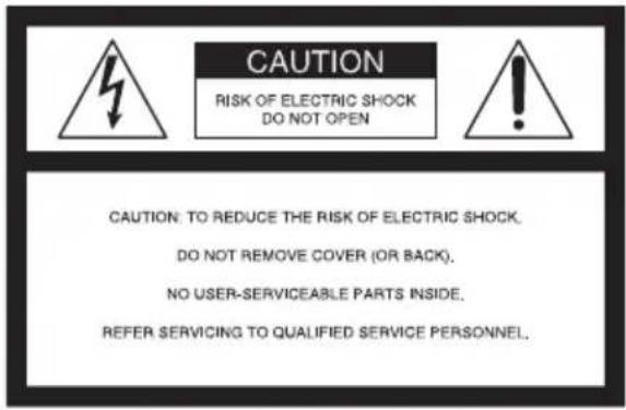
This symbol is intended to alert the user to the presence of uninsulated “dangerous voltage” within the product’s enclosure that may be of sufficient magnitude to constitute a risk of electric shock to persons.

This symbol is intended to alert the user to the presence of important operating and maintenance (servicing) instructions in the literature accompanying the appliance.
WARNING: THIS WARNING IS APPLICABLE FOR USA ONLY.
If used in USA, use the UL LISTED power cord specified below. DO NOT USE ANY OTHER POWER CORD.
Plug Cap Parallel blade with ground pin (NEMA 5-15P Configuration)
Cord Type SJT, three 16 or 18 AWG wires
Length Minimum 1.5 m, Less than 2.5 m (8 ft. 3 in.)
Rating Minimum 10 A, 125 V
Using this unit at a voltage other than 120 V may require the use of a different line cord or attachment plug, or both. To reduce the risk of fire or electric shock, refer servicing to qualified service personnel.
WARNING: THIS WARNING IS APPLICABLE FOR OTHER COUNTRIES.
- Use the approved Power Cord (3-core mains lead) / Appliance Connector / Plug with earthing-contacts that conforms to the safety regulations of each country if applicable.
- Use the Power Cord (3-core mains lead) / Appliance Connector / Plug conforming to the proper ratings (Voltage, Ampere).
If you have questions on the use of the above Power Cord / Appliance Connector / Plug, please consult a qualified service personnel.
For the customers in the U.S.A.
This equipment has been tested and found to comply with the limits for a Class B digital device, pursuant to Part 15 of the FCC Rules. These limits are designed to provide reasonable protection against harmful interference in a residential installation. This equipment generates, uses, and can radiate radio frequency energy and, if not installed and used in accordance with the instruction manual, may cause harmful interference to radio communications. However, there is no guarantee that interference will not occur in a particular installation. If this equipment does cause harmful interference to radio or television reception, which can be determined by
turning the equipment off and on, the user is encouraged to try to correct the interference by one or more of the following measures:
—Reorient or relocate the receiving antenna.
—Increase the separation between the equipment and receiver.
—Connect the equipment into an outlet on a circuit different from that to which the receiver is connected.
—Consult the dealer or an experienced radio/TV technician for help.
You are cautioned that any changes or modifications not expressly approved in this manual could void your authority to operate this equipment.
All interface cables used to connect peripherals must be shielded in order to comply with the limits for a digital device pursuant to Subpart B of Part 15 of FCC Rules.
For the customers in Europe
This product with the CE marking complies with the EMC Directive issued by the Commission of the European Community.
Compliance with this directive implies conformity to the following European standards:
• EN55103-1 : Electromagnetic Interference(Emission)
• EN55103-2 : Electromagnetic Susceptibility(Immunity)
This product is intended for use in the following Electromagnetic
Environments: E1 (residential), E2 (commercial and light industrial), E3 (urban outdoors), E4 (controlled EMC environment, ex. TV studio).
For the customers in Europe
The manufacturer of this product is Sony Corporation, 1-7-1 Konan, Minato-ku, Tokyo, 108-0075 Japan. The Authorized Representative for EMC and product safety is Sony Deutschland GmbH, Hedelfinger Strasse 61, 70327 Stuttgart, Germany. For any service or guarantee matters please refer to the addresses given in separate service or guarantee documents.
For the customers in the U.S.A. SONY LIMITED WARRANTY -
Please visit http://www.sony.com/psa/warranty for important information and complete terms and conditions of Sony's limited warranty applicable to this product.
For the customers in Canada SONY LIMITED WARRANTY -
Please visit http://www.sonybiz.ca/solutions/Support.do for important information and complete terms and conditions of Sony's limited warranty applicable to this product.
For the customers in Europe
Sony Professional Solutions Europe - Standard Warranty and Exceptions on Standard Warranty.
Please visit http://www.pro.sony.eu/warranty for important information and complete terms and conditions.
For the customers in Korea SONY LIMITED WARRANTY -
Please visit http://bpeng.sony.co.kr/ handler/BPAS-Start for important information and complete terms and conditions of Sony's limited warranty applicable to this product.
Table of Contents
Overview 21
Features 21
Precautions 22
Location and Function of Parts.... 23
Charging 25
Attaching Battery Packs 25
Charging a Battery Pack 26
Specifications 27
Overview
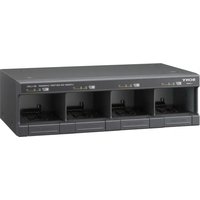
The BC-L70 Battery Charger is capable of simultaneous, continuous charging of any two of the lithium-ion battery packs.
Note
The BC-L70 cannot charge nickel metal hydride battery packs BP-M50 or BP-M100.
Features
Up to two battery packs can be attached
Up to two battery packs can be attached and charged simultaneously.
Efficient charging
The BC-L70 features a new charging system that allows quick, efficient charging of two battery packs.
Compact and lightweight
The BC-L70 is compact, lightweight, and easy to carry.
Diagnostics functions
The BC-L70 checks connected battery packs for abnormalities. Orange and green indicators will flash alternately if a battery pack cannot be charged normally.
Charge progress indicator
The orange indicator lights to show when a battery pack is charged less than 80%, and the green one when 80% or more.
Up to 100 W DC power supply
The BC-L70 supplies DC power of 16.7 V, 6 A at maximum to a device whose maximum input voltage is 17 V.
Battery backup
Should the AC power cord be accidentally unplugged from the AC power source or the O side of the POWER switch be pressed, a charged lithium-ion battery pack attached to the BC-L70 provides an alternate backup power to the connected device.
Note
The DC-L1 (NP-1B adaptor) and DC-L90 (BP-90A adaptor) cannot be used to charge nickel-cadmium battery packs.
Precautions
On the battery charger
- Use the BC-L70 in an operating environment of 0^ to 45^ (32°F to 113°F). Since charging is difficult at low temperatures, we recommend that battery packs be charged between 10^ and 30^ (50°F and 86°F).
- Avoid using or storing the BC-L70 in dusty places or places with corrosive gases.
- Avoid using or storing the BC-L70 in places exposed to direct sunlight.
- Do not cover the ventilation holes.
On battery packs
- Even when fully charged, battery packs gradually lose their charge naturally. Use the battery packs as soon as possible after charging.
- Carry and store battery packs by installing them in your equipment or by repacking them using the original packing material.
- To prolong the life of battery packs, store them in a cool place (about 20^ ( 68^ )), and charge in a place with an ambient temperature between 10^ and 30^ ( 50^ and 86^ ).
- When temperatures are 10^ (50°F) or lower, the performance of a battery pack suffers and the usable time of a battery pack becomes shorter. To get the longest usable time, warm the battery packs to room temperature (about 20^ (68°F)) before use.
- Carrying a spare battery pack is recommended.
Lithium-ion battery packs are free from memory effect. There is no need to discharge them fully before recharging.
If the usable time of a battery pack becomes very short, it is time to replace it with a new one.
Note about the battery terminal
The battery terminal of this unit (the connector for battery packs and AC adaptors) is a consumable part.
Power may not be supplied to the unit properly if the pins of the battery terminal are bent or deformed by shock or vibrations, or if they become corroded due to prolonged outdoor use.
Periodic inspections are recommended to keep the unit working properly and to prolong its usable lifetime.
Contact a Sony service or sales representative for more information about inspections.
Location and Function of Parts
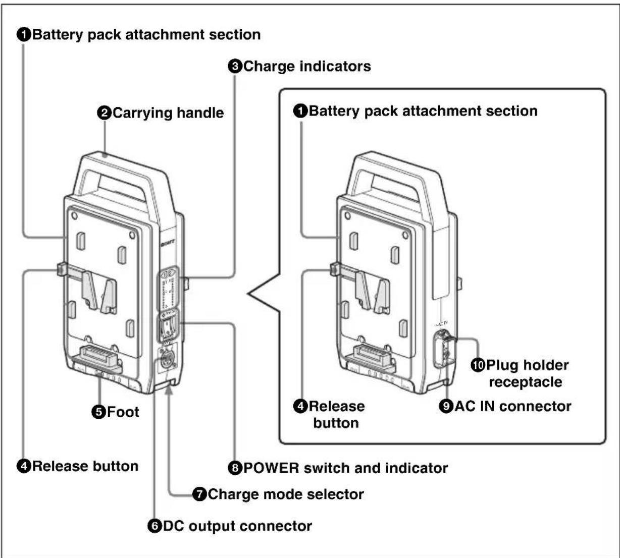
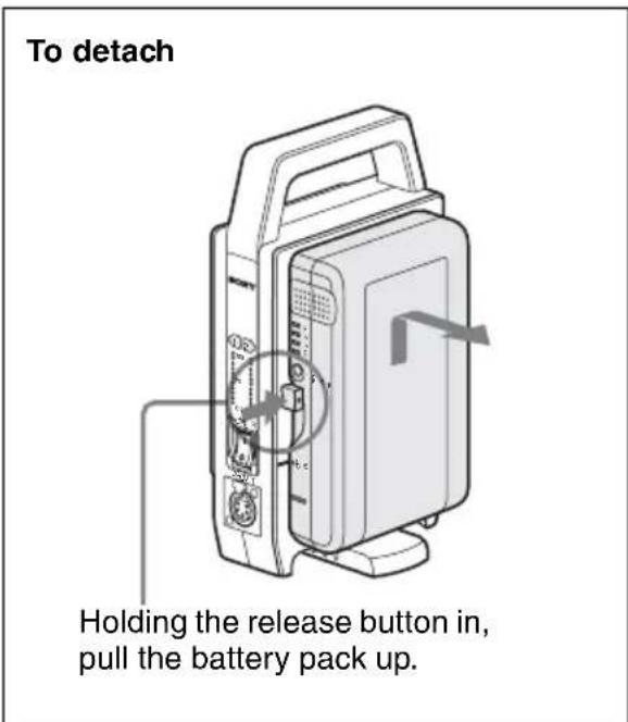
①Battery pack attachment section
When you detach a battery pack, pull it up, holding the release button in.
②Carrying handle
Used to carry this unit.
③ Charge indicators
The orange and green charge indicators indicate the progress or result of charging by flashing or lighting.
Orange indicator flashing: Charge in progress (less than 80%)
Green indicator flashing: Charge in progress (charged 80% or more)
Green indicator lit: End of charging
Orange and green indicators flashing alternately: An abnormality has been detected during charging.
④ Release buttons
Press to release the attached battery pack.
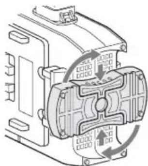
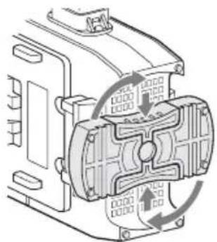
⑤Foot
Before charging a battery pack, rotate the foot as shown in the figure to stabilize the unit during charging.
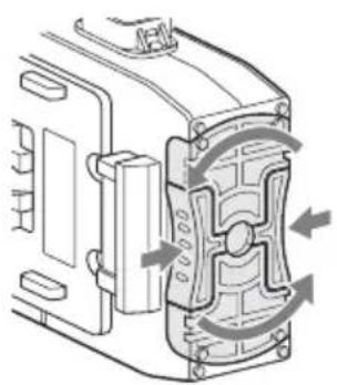
natural_image
Technical line drawing of a mechanical component with directional arrows indicating motion or flow (no text or symbols)Push in on both sides of the foot and rotate it.
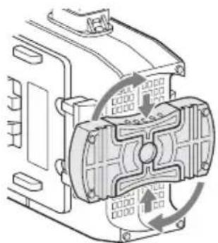
natural_image
Technical line drawing of a mechanical assembly with no visible text or symbolsTo return the foot to its original position, push in at the same positions and rotate it.
⑥DC output connector (XLR 4-pin)
Supplies DC power using a DC power cord (not supplied).
⑦ Charge mode selector
| Selector position | Charge mode |
| H Batteries are charged to their full capacity. | |
| L Charge amount is reduced, but it prolongs battery life. | |
⑧ POWER switch and indicator
Once you press the I side of this switch, power is supplied, and the associated indicator lights up. The battery packs are charged simultaneously.
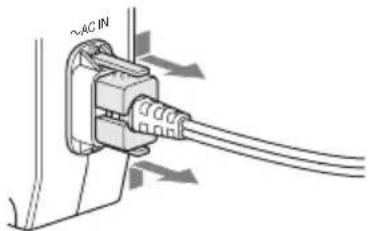
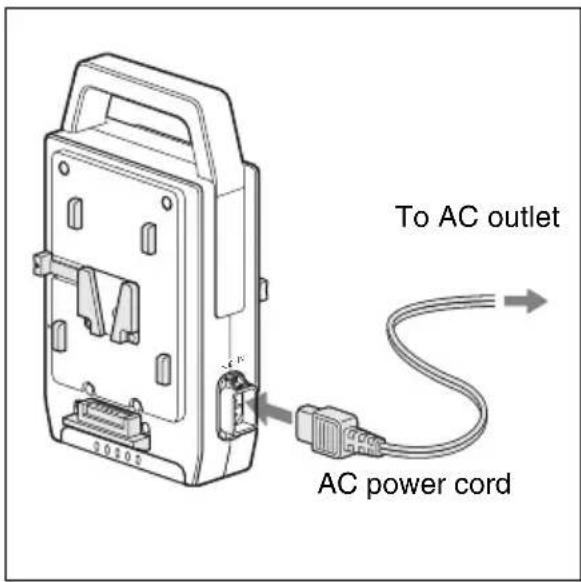
⑨\~AC IN (AC power input) connector
Used to connect the charger to an AC outlet via the AC power cord.
⑩ Plug holder receptacle
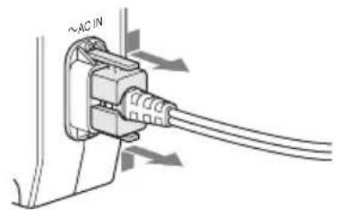
The supplied plug holder secures the cord so that it will not come loose from the charger.
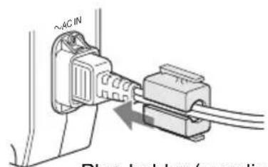
Plug holder (supplied)
To remove
Charging
For safety, use only the Sony battery packs listed below.
• Lithium-ion Battery Pack: BP-GL95A/GL65A BP-L80S/L60S
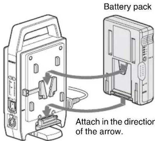
Attaching Battery Packs
Attach and detach a battery pack to be charged as shown below.
When you attach a battery pack on the other side, you can charge two battery packs simultaneously.
To attach
BC-L70
Charging a Battery Pack
1 Plug in the AC power cord to the AC IN connector and connect the other end of the cord to an AC power outlet.
2 Press the I side of the POWER switch.
Charging starts automatically. The charge indicators flash according to the process of charging.
When charging is completed, the green indicator lights.
After charging
When charging is completed, detach the charged battery pack and press the side of the POWER switch to turn the power off.
Charging time
The time to charge a completely exhausted battery pack to its full capacity is shown in the table below (when charging a battery pack at a temperature of 25^ C ( 57^ F) without supplying DC power to the connected device).
| Battery pack | Charging time to full capacity |
| BP-GL95A | About 145 minutes |
| BP-GL65A | About 155 minutes |
| BP-L80S | About 210 minutes |
| BP-L60S | About 150 minutes |
Note
When you use the BC-L70, be sure to stand it vertically, as shown in the figure on the left, to avoid problems such as over heating.
About the charging indicator
The charging indicator shows the charging status of the attached battery pack, as shown in the table below.
| Indicator status | Charging status |
| Orange indicator flashing | In progress (less than 80% of full capacity) |
| Green indicator flashing | In progress (80% or more to less than 100% of full capacity) |
| Green indicator lit | Fully charged |
| Orange and green indicators flashing alternately | An abnormality was detected. (For details see “When an abnormality is detected while charging” below.) |
When an abnormality is detected while charging
When one of the following conditions is detected while charging, the orange and green charge indicators flash alternately, and charging is canceled to protect the battery pack.
• After the start of charging, the voltage of the DC output for battery charging has dropped below the specified level (6 V).
• After the start of charging, the voltage of the DC output for battery charging has exceeded the specified level (17.5 V).
- The battery voltage did not rise to the specified level within a specified period (2 hours).
The charging indicators remain flashing until the ○ side of the POWER switch is pressed, the AC power cord is disconnected, or the battery pack is removed.
Notes
- When a battery pack that is not chargeable with the BC-L70 is connected, charging does not take place.
- The BP-M50/M100 Nickel Metal Hydride Battery Packs cannot be charged with the BC-L70.
Specifications
General
Voltage source 100–240V AC, 50/60 Hz
Current drain 168 VA or less
Peak inrush current (1) Power ON, current probe method: 15 A (100 V)/35 A (240 V) (2) Hot switching inrush current, measured in accordance with European standard EN55103-1: 12 A (230 V)
Operating temperature 0°C to 45°C (32°F to 113°F)
Mass Approx. 1.2 kg (2 lb 10 oz)
Dimensions (w/h/d) 134 × 237 × 60 mm (5^3/8 × 9^3/8 × 2^3/_8 inches) (excluding projecting parts)
Input/output
Current input (AC) 140 VA 1.4 A at maximum
Power output (DC) 100 W at maximum
Voltage output (DC) 16.8 V
Current output (DC) 6 A at maximum
DC output connector XLR-type 4-pin connector 16.7 V
Battery charging connector (DC) Square-shaped 5-pin connector 16.8 V, 5 A/3 A
Supplied accessories
Operation Manual (1)
AC power cord (USA only) (1)
Plug holder (1)
Optional accessory
DC power cord
Design and specifications are subject to change without notice.
Note
Always verify that the unit is operating properly before use. SONY WILL NOT BE LIABLE FOR DAMAGES OF ANY KIND INCLUDING, BUT NOT LIMITED TO, COMPENSATION OR REIMBURSEMENT ON ACCOUNT OF THE LOSS OF PRESENT OR PROSPECTIVE PROFITS DUE TO FAILURE OF THIS UNIT, EITHER DURING THE WARRANTY PERIOD OR AFTER EXPIRATION OF THE WARRANTY, OR FOR ANY OTHER REASON WHATSOEVER.
Français
natural_image
Technical diagram of a mechanical component with directional arrows indicating motion or force (no text or symbols present)natural_image
Technical diagram of a mechanical assembly with internal components and directional arrows indicating motion (no text or labels)natural_image
Technical line drawing of a portable electronic device with ports and control panel (no text or symbols)natural_image
Technical diagram of a mechanical assembly with directional arrows indicating motion or force (no text or symbols present)natural_image
Technical line drawing of a mechanical assembly with no visible text or symbolsnatural_image
Diagram of a computer case with ports and control panel (no text or symbols)natural_image
Mechanical assembly diagram showing a motor or gear mechanism with rotational arrows indicating motion (no text or symbols present)natural_image
Technical diagram of a mechanical assembly with internal components and directional arrows indicating motion (no text or labels)natural_image
Technical line drawing of a mechanical component with circular arrows indicating motion or assembly (no text or symbols)natural_image
Mechanical assembly diagram showing a motor or gear mechanism with rotating components (no text or labels)natural_image
Technical diagram of a mechanical assembly with directional arrows indicating motion or flow (no text or symbols present)推入脚座的两侧,然后旋转脚座。
natural_image
Mechanical assembly diagram showing internal components and rotational flow arrows (no text or labels)natural_image
Diagram of a computer tower with control panel and indicator lights (no text or symbols)握住释放按钮,然后拉起电池。
为电池充电
The material contained in this manual consists of information that is the property of Sony Corporation and is intended solely for use by the purchasers of the equipment described in this manual.
Sony Corporation expressly prohibits the duplication of any portion of this manual or the use thereof for any purpose other than the operation or maintenance of the equipment described in this manual without the express written permission of Sony Corporation.
Printed on recycled paper.
Printed in Japan
2014.09 32
©2005