USER MANUAL ForceClima 7150 Style CECOTEC
FORCECLIMA 7550 STYLE CONNECTED
FORCECLIMA 9150 STYLE
FORCECLIMA 9450 STYLE HEATING
FORCECLIMA 9550 STYLE HEATING CONNECTED
FORCECLIMA 12650 STYLE HEATING
FORCECLIMA 12850 STYLE HEATING CONNECTED
Aire acondiconado portátil/ Portable air conditioner
Safety instructions 9
- Parts and components
2.Before use
-
Product installation
-
Operation
5.Cleaning and maintenance
-
Troubleshooting 79
-
Technical specifications 84
-
Disposal of old electrical and
electronic appliances
-
Technical support and warranty
-
Copyright
-
Declaration of conformity
SOMMAIRE
7 Specifications techniques
Read these instructions thoroughly before using the device. Keep this instruction manual for future reference or new users.
- This device is designed for domestic use only and is not intended for bars, restaurants, farmhouses, hotels, motels, and offices.
- This appliance can be used by children aged 8 years and above and people with reduced physical, sensory, or mental capabilities or lack of experience and knowledge if they have been given supervision or instruction concerning use of the appliance in a safe way and understand the hazards involved. Children must not play with the appliance. Cleaning and user maintenance should not be carried out by unsupervised children.
- The device must be powered at a low safety voltage as stated on the marking.
- If the power cable is damaged, it must be replaced by the official Cecotec Technical Support Service or similar qualified personnel to avoid risks.
- The installation of pipelines should be kept to a minimum.
- Pipelines must be protected from physical damage and must not be installed in an unventilated space.
- Compliance with national gas regulations must be observed.
- Mechanical connections shall be accessible for maintenance purposes.
- The minimum room floor area for the room in which the appliance can be placed is 12m^2
- WARNING: keep the ventilation openings clear from obstructions.
-
NOTE: servicing should be performed only as recommended by the manufacturer.
-
The appliance shall be installed in accordance with national electrical installation regulations
- WARNING: the appliance must be stored in a well-ventilated area where the room size corresponds to the room area as specified for operation.
- WARNING: the appliance must be stored in a room without continuously operating open flames (e.g. an operating gas appliance) or sources of ignition (e.g. an operating electric heater).
- The appliance must be stored in such a way as to prevent mechanical damage.
- Any person involved in work or intervention on a refrigerant circuit should hold a current valid certificate issued by an industry-accredited assessment authority, authorising their competence to handle refrigerants safely in accordance with an industry-recognised assessment specification.
Servicing should only be carried out as recommended by the equipment manufacturer. Maintenance and repairs requiring the assistance of other qualified personnel must be carried out under the supervision of the person competent in the use of flammable refrigerants.
- Service personnel must be instructed to perform the following when servicing an appliance using a flammable refrigerant.
- Make sure that the mains voltage matches the voltage stated on the rating label of the appliance and that the wall outlet is earthed.
-
Do not immerse the cable, plug, or any other non-removable part of the appliance in water or any other liquid. Do not expose the electrical connections to water. Make sure your hands are dry before handling the plug or switching on the device.
-
Do not carry or pull the appliance from the power cable. Do not use the power cable as handle. Do not push the cable against corners or sharp edges. Do not crush the power cable with the full weight of the appliance. Keep the cable away from hot surfaces.
- Do not operate the appliance if its cable, plug, or body show visible damage, do not operate properly, or have been dropped.
- Do not use the appliance in confined spaces with explosive or flammable vapours.
- Keep the portable air conditioner away from heat sources.
- Do not try to repair the appliance by yourself. Contact the official Cecotec Technical Support Service.
- Do not install and use the portable air conditioner in the bathroom or other humid environments.
- The portable air conditioner is designed for indoor use only and is not compatible with other uses.
Instructions on batteries
- Battery ingestion can cause burns, soft-tissue perforation, and death. It can cause severe burns within two hours of the ingestion.
- In case of battery ingestion, please seek medical attention immediately.
- Do not allow children to replace batteries without adult supervision.
- Do not disassemble, open, or damage the batteries.
- Keep the batteries out of the reach of children. Pay particular attention to small batteries. In case of battery ingestion, please seek medical attention immediately.
-
Do not expose batteries to heat or fire. Avoid storage in direct sunlight.
-
Do not short-circuit an element or a battery. Do not store batteries in an untidy manner, in a box, or drawer where they can short-circuit each other or be short-circuited by other metal objects.
- Do not subject batteries to mechanical shock.
- Both batteries and cells can leak under extreme conditions. In the event of a battery leak, keep your skin and eyes away from the liquid. If the liquid gets into contact with skin, wash immediately with soap and water. If the liquid gets into the eyes, wash them immediately with clean water for a minimum of 10 minutes and seek medical attention. Wear gloves to handle the battery and dispose of it immediately in accordance with local regulations.
- Pay attention to the positive (+) and negative (-) marks on the batteries and the remote-control compartment to ensure they are inserted correctly.
- Do not use any batteries that are not designed for use with the appliance.
- Do not use the remote control if powered with batteries that differ in capacity, size, or type.
- Children should be allowed to handle the batteries only under adult supervision.
- Always buy recommended batteries.
- Keep the batteries clean and dry. Wipe the battery terminals with a clean, dry cloth if they become dirty.
- Keep the original instruction manual for future reference.
- Use the batteries only for their intended purpose.
- Whenever possible, remove the batteries when not in use.
INSTRUCTIONS DE SECURITÉ
FORCLUAA750STYLE/FORCLUAA750STYLECONNCTL/DFORCLUAA750STYLE
FORCLUMA 5AS0 STYLE HEATING / FORCLUMA 5550 STYLE HEATING CONNECTED/ FORCLUMA12650 STYLE HEATING
FORCECUA 12B50 STYLE HEATING CONNECTED
FORCLIMA 750 STYLE/ FORCLIMA 750 STYLE CONNECTED/ FORCLIMA 9150 STYLE
FORCLLIMA 9450 STYLE HEATING / FORCLCUMA 9550 STYLE HEATING CONNECTED/ FORCLCIMIA 12650 STYLE HEATING
FORCLICUM 12B5G STYLE HEATING CONNECTED
ESPANOLESPANOL
FORCLIMA 750 STYLL/ FORCLIMA 750 STYLL CONNECTED/ FORCLIMA 950 STYLE FORCLIMA 940STYLELATING/ FORCLIMA 950 STYLE LATING CONNECTED/ FORCLIMA 1200 STYLE LATING CONNECTED FORCLIMA 1200 STYLE LATING CONNECTED
ESPANOLESPANOL
1.7.Areaventilada
- Exhaust hose
- Window connector
- Adapter
- Hose connector
- Window kit panel
- Dowels
- Water pipe (only for models with heat pump)
Control panel (only for models 08162 and 08164)
Fig 3
- Full-tank indicator light
- Cool mode indicator Light
- Dehumidification mode indicator light
- Fan indicator light
- Low speed indicator Light
- High speed indicator light
- Sleep mode indicator light
- On/off button
- Modes button
- Temperature decrease button
- Timer button
- Temperature Increase button
- Fan speed bu
- Sleep mode button
Control panel (only for model 08163)
Fig.4
-
Full-tank indicator light
-
Cool mode indicator light
- Dehumidification mode indicator light
- Fan
- Low speed indicator light
- High speed Indicator Light
- Sleep mode indicator light
8.Wi-Fiindicatorlight
- On/off button
- Modes button
- Temperature decrease button
- Timer
- Temperature Increase button
- Fan speed
- Sleep mode button
Control panel (only for models 08165 and 08167)
Fig.5
4. Fan
- Full-tank indicator light
- Cool mode indicator light
- Dehumidification mode indicator light
- Low speed indicator light
- High speed indicator light
- Sleep mode indicator light
- Heat mode indicator light
- On/off button
- Mades button
- Temperature decrease button
- Timer
- Temperature increase button
- Fan speed
- Sleep mode button
Control panel (only for models 08165 and 0816B)
Fig. 6.
- Full-tank indicator Light
- Cool mode indicator light
- Dehumidification mode indicator light
- Fan
- Low speed indicator light
- High speed indicator light
ENGLISHENGLISH
- Sleep mode indicator light
- Heat mode indicator light
- Wi-Fi indicator Light
- On/off button
- Modes button
- Temperature decrease button
- Timer
- Temperature increase button
- Fan speed
- Sleep mode button
Remote control (only for models 08162, 08163, 08164, 08165 and 08166)
Fig.7
1. On/off button
2. Timer
3. Modes button
4.Temperature decrease button
5. Temperature increase button
6. Fan speed
7. Sleep mode
Remote control (only for models 08167 and 08168)
Fig.8
1. On/off button
2. Timer
3. Modes button
4. ^ C / 口 button
5. Temperature increase button
6. Temperature decrease button
7. LED display
8. Fan speed
9. Sleep mode
Remote control display (only for models 08167 and 08168)
Fig 9
- Signal receiver
- Cool mode
- Dehumidifier mode
- Fan
- Heat mode
- Timing
72
FORCLLUMA 750 STYLE / FORCLLUMA 750 STYLE CONNCTL / FORCLLUMA 750 STYLE
FORCLUMA50STYLEHATING/ FORCLUMA550STYLEHATING CONNECTED/ FORCLUMA12650 STYLE HATING
FORCEUM12USE STYLE FLATING CONNCLTED
- Timer
- Sleep mode
- Fan speed
- Temperature indicator light
NOTE:
The graphics in this manual are schematic representations and may not exactly match the
device
2. BEFORE USE
This appliance is packaged in a way as to protect it during transport. Take the device out of its box and remove all packaging materials. You can keep the original box and other packaging elements in a safe place. This will help you prevent damage to the device when transporting it in the future. In case the original packaging is disposed of, make sure all packaging materials are recycled accordingly.
- Make sure all parts and components are included and in good conditions. If there is any piece missing or in bad conditions, contact the official Cecotec Technical Support Service immediately.
Box content
Portoair conditioner (08162, 08163, 08164, 08165, 08166, 08167 and 08168 models) Window kit
-Remote control
-Instruction manual
3.PRODUCT INSTALLATION
NOTE:
Leave a minimum of 30 cm distance to walls and other objects, as shown in figure 10.
- Do not install and use the air conditioning in the bathroom or other humid environments.
Before using the portable air conditioner, keep it upright for at least two hours. When moving the appliance from one place to another, always keep it in an upright position and leave it on a flat surface.
The air outlet pipe should be 28-150 cm long, this length is based on the specifications of the air conditioner. Do not use extendible pipes or replace the pipe with a different one, as this may cause the product to malfunction. The exhaust nose must be clear of obstructions; otherwise, it may cause overheating.
FORCOLLUMA750 STYLE/ FORCOLLUEA250 STYLE CONNECTED/ FORCOLLUA950 STYLE/ FORCOLLUAA950 STYLE HEATING CONNECTED/ FORCOLLUXA1250 STYLE/ STYLE HEATING
ENGLISHENGLISH
Air outlet pipe assembly
Temporary installation. Fig. 11
1. Screw the adapter, hose connector and window connector to the ends of the exhaust hose.
2. Insert the adapter into the openings at the back of the appliance.
3. Place the other end of the exhaust hose on the windowsill.
Window kit installation. Fig. 12
- The kit can be positioned vertically or horizontally. Check the minimum and maximum size of the window before installing it.
- Place the kit in the window.
- Adjust the length of the kit according to the width or height of the window and fix it with the dowel.
- Insert the window connector of the hole to the window kit.
NOTE:
The flat end of the exhaust hose joints must be snapped into place.
The air outlet pipe must not be twisted or bent more than 45^ . Keep the air outlet pipe free of obstructions.
The following checks must be applied to Installations using flammable refrigerants:
- The load size is in accordance with the size of the room where refrigerant-containing parts are installed.
Ventilation machinery and outlets can be properly operated and are unobstructed.
If an indirect cooling circuit is used, the secondary circuit must be checked for refrigerant presence.
Equipment marking remains visible and legible. Illegible markings and symbols should be corrected.
- The components or refrigerant piping are installed in a position where they are not susceptible to exposure to any substance that may corrode the refrigerant-containing components, unless the components are made of materials that are inherently resistant to corrosion or are properly protected against it.
4.OPERATION
The following functions can be activated from the control panel or from the remote control
On/Off
When the appliance is switched on, it will beep and enter Standby mode. Press the on/off button to switch the appliance on and off.
FORCLLUMA750STYLE/FORCLLUMA750STYLECONNNELED/FORCLLUMA950STYLE
FORCLUMA50STYLEHATING/ FORCLUMA550S STYLE HATING CONNECTED/ FORCLUMA12650 STYLE HATING
FORCEUM12USE STYLE FLATING CONNCLTED
Modes
Press the mode button to switch between cool mode, heat mode (depending on the model), fan mode and dehumidification mode.
Sleep mode
- When the appliance is in operation with the cool mode activated, press the sleep mode button to adjust the temperature. The temperature shall increase by 1^ C after one hour and by a maximum of 2^ C after 2 hours.
When the appliance is in operation with the heat mode activated, press the sleep mode button to adjust the temperature. The temperature shall decrease by 1^ after one hour and by a maximum of 2^ after 2 hours.
Press the button again to deactivate sleep mode.
△Increase and decrease
Use these buttons to increase or decrease temperature and operation time
Temperature cannot be increased or decreased in fan or dehumidification mode.
Fan speed
In cool mode, press this button to select a high or low fan speed setting.
This option is not available under the dehumidification mode.
NOTE:
Under certain conditions (defrost), it may not operate at the selected speed.
Timer
To set the switch-on time
- When the air conditioner is off, press the timer button and select the desired switch-on time using the temperature and time setting buttons.
- 'Preset ON Time' will appear on the control panel.
- You can select that the appliance switches on automatically within a period of 0 to 24 hours.
- Press the timer button again to confirm the settings and activate the function.
To deactivate this function, press the timer button repeatedly until the indicator light turns off.
To set the switch-off time
- When the air conditioner is on, press the timer button and select the desired switch-off time using the temperature and time setting buttons.
- Preset Off Time" will appear on the control panel
You can select that the appliance switches off automatically within a period of 0 to 24 hours.
FORCOLLUMA 750 STYLE / FORCOLLUPA 7500 STYLE CONNECTED/ FORCOLLUPA 950 STYLE FORCOLLUPA 9500 STYLE HEATING / FORCOLLUPA 9500 STYLE HEATING CONNECTED/ FORCOLLUPA 12600 STYLE HEATING
ENGLISHENGLISH
Press the timer button again to confirm the settings and activate the function.
- To deactivate this function, press the timer button repeatedly until the indicator light turns off.
Wi-Fi function
Scan the following QR codes to make the connection
Model B163:
Model 8166:
Model B168:


Drainage instructions
When the air conditioner stops operating because the water tank is full, turn it off and unplug it from the power supply. The full-tank indicator Light (FULL) will start flashing and the appliance will not operate until the water inside the tank is drained.
Manual drainage. Fig. 13
Full tank warning
This portable air conditioner has a sensor in the tank that monitors the water level. When the sensor detects that the tank is full and, thus, must be emptied, the corresponding indicator light will light up. Remove the rubber cap from the bottom to drain all the water.
Protection features
Frost protection function
In cool and dehumidification modes, if the temperature of the evaporator outlet pipe is too low, the appliance will automatically enter protection mode to prevent damage to the evaporator. The appliance will restart when the temperature is restored to normal values.
Condensate water flood protection function
When the water level exceeds the maximum level allowed by the safety buoy, the appliance will switch off and activate the FULL indicator light on the control panel. To restart the device, the water inside the device will need to be drained through the bottom drain plug (shown in detail in the drainage instructions section). Once the water has been drained, the device will restart.
FORCLLUMA 750 STYLE / FORCLLUMA 750 STYLE CONNCTL / FORCLLUMA 750 STYLE
FOR LORCLUPA 5405 STYLE HEATING- / FOR LORCLUPA 8550 STYLE HEATING CONNECTED / FOR LORCLUPA 1250 STYLE HEATING CONNECTED FOR LORCLUPA 1250 STYLE HEATING CONNECTED
5. CLEANING AND MAINTENANCE
Before cleaning the appliance, disconnect it from the mains.
- Do not use petrol or any chemical products for cleaning.
Do not wash the appliance directly with water.
If it is damaged, please contact the official Cecotec Technical Support Service.
Air filter
The air filter can become clogged by dust or dirt build-up. For that reason, we recommend that you clean it once every two weeks.
-Removal
Open the air inlet grille first and remove the filter.
- Cleaning
- Wash the filter with a neutral soap and dry it thoroughly.
- Reinsertion
Put it back into place.
Cleaning the air conditioner surface
Clean the surface of the air conditioner with a neutral soap and a damp cloth. Dry it well with another cloth.
Storage
Store the device in well ventilated areas.
Unscrew the drain cap, unplug the water plug, and discharge the water in the water tank into other water containers or directly tilt the body to discharge the water into other containers.
Turn on the appliance, adjust it to low wind ventilation mode, and maintain this state until the drainage place becomes dry. This way, you will keep the inside of the body in a dry state and prevent it from mildestewing.
Turn off the appliance, unplug the power plug, and wrap the power cord around the wrapping post. Install the water plug and the drain cap.
- Remove the exhaust hose and keep it properly.
- Cover the air conditioning with a plastic bag. Put the air conditioning in a dry place, keep it out of the reach of children, and take out control measures.
Remove batteries of the remote control and keep them properly.
- Ensure that the body is placed in a dry place and keep all machine components properly.
Maintenance
Any person who is involved with working on or breaking into a refrigerant circuit should hold a current valid certificate from an industry-accredited assessment authority, which authorises their competence to handle refrigerants safely in accordance with an industry recognised assessment specification.
FORCLIMA 750 STYLE / FORCLIMA 750 STYLE CONNECTED/ FORCLIMA 9150 STYLE
FORCLIMA 9450 STYLE LATING / FORCLIMA 9550 STYLE LATING CONNECTLD/ FORCLIMA 1260 STYLE HEATING
FORCELUM 12B50 STYLE HEATING CONNECTED
ENGLISH ENGLISH
6.TROUBLESHOOTING
| Problem Possible causes Possible solutions | |
| 1. The appliance does not switch on when pressing the on/off button | The water tank is full, and the indicator light is flashing. | Empty the water tank. |
| The room temperature is higher than the selected temperature (in heat mode). | Adjust the temperature. |
| The room temperature is lower than the selected temperature (in cool mode). | Adjust the temperature. |
| 2. It does not cool enough | There is a window or a door open. | Make sure that all windows and doors are properly closed. |
| There is a heat source inside the room. | If possible, remove the heat source from the room. |
| The exhaust hose is not properly positioned or is blocked. | Fit it properly or clean it. |
| The temperature is too high. | Adjust the temperature. |
| The air outlet is blocked. Clean it. |
| 3. The appliance makes noise | The floor is not level or not flat enough. | If possible, place the device on a flat and level floor. |
| The sound comes from the airflow inside the appliance. | This is normal. |
| 4. E0 Code Room temperature sensor fault. | Change the sensor (the appliance can be used without this sensor). |
| 5. E1 Code Condenser temperature sensor fault. | Change the sensor. |
| 6. E2 Code The water tank is full when the cool mode is in operation. | Remove the rubber cap and drain the water. |
| 7. E3 Code Evaporator temperature sensor fault. | Change the sensor. |
| 8. E4 Code The water tank is full when the heat mode is in operation. | Empty the water. |
1.1 Area verification
Before starting work on systems containing flammable refrigerants, safety checks are necessary to ensure that the risk of ignition is minimised. Before repairing the cooling system, the following precautions must be observed:
1.2. Work procedure
The work must be carried out in accordance with a controlled procedure to minimise the risk of a flammable vapour or gas being present while the work is being carried out.
1.3.General workspace
All maintenance personnel and others working in the area should be briefed on the nature of the work to be carried out. Work in confined spaces must be avoided. The area around the workspace should be divided into sections. Ensure that conditions within the workspace are safe by keeping flammable material under control.
1.4. Refrigerant verification
The area should be checked with an appropriate refrigerant detector before and during work to ensure that the technician is warned of potentially flammable atmospheres. Ensure that the leak-detection equipment used is suitable for use with flammable refrigerants. i.e. non-sparking, adequately sealed, or intrinsically safe.
ENGLISHENGLISH
1.5. Presence of fire extinguishers
If any high-temperature work is to be carried out on the refrigeration equipment or any associated parts, suitable extinguishing equipment must be available. Always have a cry-powder or CO2 fire extinguisher nearby the load area.
1.6. Absence of ignition sources
No person carrying out work related to a refrigeration system involving the exposure of piping containing or having contained flammable refrigerant should use any source of ignition in such a manner as to create a risk of fire or explosion. All possible sources of ignition, including cigarette smoking, should be kept far enough away from the installation, repair, pick-up, and disposal site, where flammable refrigerant can be released into the surrounding space. Before work starts, the area around the equipment must be thoroughly examined to ensure that no danger or risk of ignition is present. "No Smoking" signs must be displayed.
1.7.Ventilation
Ensure that the area is outdoors or adequately ventilated before Intervening in the system or carrying out any work at high temperature. Proper ventilation must be kept at all times during work. Ventilation should safely disperse any refrigerant released and preferably expel it externally to the atmosphere.
1.8. Verification of refrigeration equipment
When electrical components are replaced, they must be fit for purpose and to the correct specification. The manufacturer's maintenance and service guidelines must be followed at all times. In case of doubt, refer to the manufacturer's technical department for assistance.
The following checks must be applied to installations using flammable refrigerants:
- The load size is in accordance with the size of the room where refrigerant-containing parts are installed.
- Ventilation machinery and outlets can be properly operated and are unobstructed.
If an indirect cooling circuit is used, the secondary circuit must be checked for refrigerant presence.
- Equipment marking remains visible and legible. Illegible markings and symbols should be corrected.
- The components or refrigerant piping are installed in a position where they are not susceptible to exposure to any substance that may corrode the refrigerant-containing components, unless the components are made of materials that are inherently resistant to corrosion or are properly protected against it.
1.9. Verification of electrical devices
Repair and maintenance of electrical components should include initial safety checks and component-inspection procedures. If there is a fault that may compromise safety, then no power supply should be connected to the circuit until the fault is satisfactorily dealt with. If
the fault cannot be corrected immediately, but continued operation is necessary, a suitable temporary solution must be used. This should be reported to the owner of the equipment so as to inform all parties.
During initial safety checks, make sure
that capacitors are unloaded this must be done in a safe manner to avoid sparks.
that no live wiring or electrical components are exposed while loading, recovering, or purging the system;
that there is continuity in the earth connection.
2. Repair of sealed components
During the repair of scaled components, all power supplies should be disconnected from the equipment being worked on prior to any removal of scaled covers, etc. If it is absolutely necessary to have a power supply to the equipment during service, then a permanently operating form of leak detection should be placed at the most critical point to warn of a potentially hazardous situation.
Particular attention must be paid to the following to ensure that, when working on electrical components, the housing is not altered in such a way as to affect safety. This must include damage to cords, an excessive number of connections, terminals not conforming to the initial specification, damage to seals, incorrect fitting of the stuffing box, etc.
- Ensure that the Instrumentation is securely mounted.
- Ensure that seals or sealing materials have not degraded until no longer being useful to preventing the penetration of flammable atmospheres. Spare parts must be in accordance with the manufacturer's specifications.
NOTE: the use of silicone sealant may inhibit the effectiveness of some types of leak-detection equipment. Intrinsically safe components do not have to be isolated before work.
3. Repair of intrinsically safe components
- Do not apply any permanent inductive or capacitive load to the circuit without ensuring that it will not exceed the permissible voltage and current rating for the equipment in use.
- Intrinsically safe components are the only type of components that can be worked on in a flammable atmosphere. The test instrumentation must have the correct assigned features.
- Replace components only with parts specified by the manufacturer. Other parts can ignite the refrigerant in the atmosphere from a leak.
4. Wiring
Verify that the wiring is not subject to wear, corrosion, excessive pressure, vibration, sharp edges, or any other environmental effects. The verification should also take into account the effects of ageing or continuous vibration from sources such as compressors or fans.
ENGLISHENGLISH
5.Detection of flammable refrigerants
Under no circumstances should potential ignition sources be used in the search for or detection of refrigerant leaks. Do not use a halide lamp or any other detector using a naked flame.
6. Leak-detection methods
- The following leak-detection methods are considered acceptable for systems containing flammable refrigerants.
Electronic leak detectors should be used to detect flammable refrigerants, but the sensitivity may not be adequate, or may need recalibration (the detection equipment should be calibrated in a refrigerant-free area). Ensure that the detector is not a potential ignition source and that it is suitable for the refrigerant used. The leak-detection equipment must be set to a percentage of the lower flammability limit of the refrigerant and calibrated for the refrigerant used with the appropriate percentage of gas (maximum 25%) confirmed.
Leak-detection fluids are suitable for use with most refrigerants, but the use of detergents containing chlorine must be avoided. as chlorine can react with the refrigerant and corrode copper pipes.
- If a leak is suspected, all naked flames must be eliminated/extinguished.
If a refrigerant leak is found and requires brazing, all refrigerants must be recovered from the system, or isolated (by means of shut-off valves) in a part of the system far away from the leak. Oxygen-free nitrogen must then be purged through the system both before and during the brazing process.
7. Removal and evacuation
When intervening in the cooling circuit for repairs or any other purpose, conventional procedures must be followed. However, it is important that best practices are followed, as flammability is a matter to be taken seriously. The following procedure is to be followed:
- Remove the refrigerant.
- Purge the circuit with inert gas.
- Evacuate.
- Purge again with inert gas.
- Open the circuit by cutting or brazing.
- The refrigerant charge must be recovered from the correct recovery cylinders. The system must be flushed with oxygen-free nitrogen to render the unit safe. This process may need to be repeated several times. Oxygen or compressed air must not be used for the task.
- Cleanliness must be achieved by breaking the vacuum in the system with oxygen-free nitrogen and continuing to fill until working pressure is reached, then venting to atmosphere, and finally pushing to a vacuum. This process must be repeated until there is no refrigerant left in the system. When using the oxygen-free nitrogen end-charge the system must be vented to atmospheric pressure to allow for work. This operation is absolutely vital if brazing operations are to take place on pipes.
- Ensure that the vacuum pump outlet is not near any source of ignition and that ventilation is available.
FORCLLUMA 750 STYLE / FORCLLUMA 750 STYLE CONNECTD/ FORCLLUMA 950 STYLE
FORCLUCA 9405 SYTLLY HEATING / FORCLUCA 9520 5 STYLE HEATING CONNECTED / FORCLUCA 1250 STYLE HEATING FORCLUCA 1280 5 STYLE HEATING CONNECTED
8. Loading procedure
In addition to conventional loading procedures, the following requirements must be followed.
- Ensure that no contamination of different refrigerants occurs when using the loading equipment. Hoses or lines should be kept as short as possible to minimise the amount of refrigerant contained in them.
- Cylinders must be kept in an upright position.
- Ensure that the refrigeration system is grounded before loading the system with refrigerant.
- Tag the system when charging is complete (if not already).
Extreme care must be taken to avoid overfilling the cooling system.
Before reloading, the system must be pressure- tested with oxygen-free nitrogen. The system shall be leak-tested upon completion of loading, but prior to commissioning. A subsequent leakage test must be carried out before leaving the site.
9. Commissioning
Before performing this procedure, it is essential that the technician is thoroughly familiar with the equipment and all its details. It is recommended good practice that all refrigerants are safely recovered. Before the task is carried out, a sample of oil and refrigerant should be taken in case an analysis is required before the recovered coolant is reused. It is essential for there to be power before starting with the task.
A. It is important to get familiar with the equipment and its operation.
B. Electrically isolate the system
C. Before attempting the procedure, ensure that
- the mechanical-handling equipment is available, if required, for the handling of refrigerant cylinders;
- all personal protective equipment is available and correctly used;
the recovery process is supervised at all times by a competent person;
- cylinders and recovery equipment conform to appropriate standards.
D. Pump the cooling system, if possible.
E. If vacuum is not possible, make a manifold so that refrigerant can be removed from various parts of the system.
F. Ensure that the cylinder is positioned on the scale before recovery takes place.
6. Switch on the recovery machine and operate it according to the manufacturer's instructions.
H. Do not overfill cylinders (no more than 80% of the liquid charge by volume).
1. Do not exceed the maximum working pressure of the cylinder, even temporarily.
1. When the cylinders have been correctly filled and the process is complete, ensure that the cylinders and equipment are promptly removed from the site and that all equipment isolation valves are closed.
K. Recovered refrigerant must not be charged to another refrigeration system, unless cleaned and checked.
FORCLIMA 750 STYL/ FORCLIMA 750 STYL CONNECTED/ FORCLIMA 950 STYL
FORCLIMA 9450 STYLE HEATING / FORCLIMA 9550 STYLE HEATING CONNECTLD/ FORCLIMA 12000 STYLE HEATING
FORCLUMAT2B50 STYLEHEATING CONNECTED
ENGLISHENGLISH
10. Labelling
The equipment must be labelled stating that it has been taken out of service and drained of refrigerant. The labelling must be dated and signed. Ensure that there are labels on the equipment stating that the equipment contains flammable refrigerant.
11. Recovery
- When refrigerant is removed from a system, either for service or decommissioning, it is recommended good practice that all refrigerants are removed safely.
- When transferring refrigerant to cylinders, ensure that only suitable refrigerant-recovery cylinders are used. Ensure that the correct number of cylinders is available to support the total load of the system. All cylinders to be used are designated for the refrigerant recovered and labelled for that refrigerant (i.e. special refrigerant recovery cylinders). Cylinders must be completed with pressure-relief valves and associated shut-off valves in good working order. Empty recovery cylinders are evacuated and, if possible, cooled before recovery takes place.
Recovery equipment must be in good working order with a set of instructions concerning the equipment at hand and must be suitable for the recovery of flammable refrigerants. In addition, a set of calibrated weighing scales must be available and in good working order. Hoses must be complete with disconnect couplings free of leakage and in good running order. Before using the recovery machine, check that it is in good running order, properly maintained, and that all associated electrical components are sealed to prevent ignition in the event of refrigerant release. Consult the manufacturer in case of doubt.
The flammable refrigerant must be returned to the refrigerant supplier in the correct recovery cylinder, and the applicable waste transfer note must be provided. Do not mix refrigerants in recovery units and especially not in cylinders.
If compressors and compressor oils are to be removed, ensure that they have been drained to an acceptable level so that no flammable refrigerant remains within the lubricant. The evacuation process must be carried out before returning the compressor to the suppliers. Only electrical heating of the compressor body should be used to accelerate this process. When oil is drained from a system, it must be done in a safe manner.
7. TECHNICAL SPECIFICATIONS
Product reference: 08162 / 08163 / 08164 / 08165 / 08166 / 08167 / 08168 Product:
ForceCima 7150 Style portable air conditioner
ForceCima 7550 Style Connected portable air conditioner
ForceClima 9150 Style portable air conditioner
ForceClima 9450 Style Heating portable air conditioner
ForceCima 9550 Style Heating Connected portable air conditioner
ForceCima 12650 Style Heating portable air conditioner
ForceClima 12850 Style Heating Connected portable air conditioner
FORCLLUMA 750 STYLE / FORCLLUMA 750 STYLE CONNECTD/ FORCLLUMA 950 STYLE
FORCLUMA 9450 STYLE HEATING / FORCLUMA 8550 STYLE HEATING CONNECTED/ FORCLUMA12650 STYLE HEATING
FORCECUA 12B50 STYLE HEATING CONNECTED
FORCLIMA750 STYLE/FORCLIMA750 STYLE CONNECTED/FORCLIMA9150 STYLE
FORCLIMA 9450 STYLE HEATING / FORCLIMA 9550 STYLE HEATING CONNECTLD/ FORCLIMA 12000 STYLE HEATING
FORCLUMAT2B50 STYLEHEATING CONNECTED
ENGLISH ENGLISH
| Model Power Supply | Rated cooling | power/ P rated | Rated heating power/ P rated | Rated power used for cooling/P EHR | Rated power used for cooling/ Por | Rated energy efficiency factor/ EHR | Rated coefficient of performance/ Cap. | Energy consumption in thermostat-off mode/ Pu | Power consumption in standby mode/ Ps |
| 08162_ForceClima 7150 Style | 220-240V, 50 HZ | 7000 BTU/h 2.0 kW | / | 785 W | / | 2.54. | N/A | N/A | 0.5W |
| 08163_ForceClima 7550 Style Connected | 7000 BTU/h 2.0 kW | / | 785 W | / | 2.54. | N/A | N/A | 2 W |
| 08164_ForceClima 9150 Style | 9000 BTU/h 2.6 kW | / | 1000 W | / | 2.6. | N/A | N/A | 0.5W |
| 08165_ForceClima 9450 Style Heating | 9000 BTU/h 2.6 kW | 6140 BTU/h 1.8 kW | 1000 W 1050 W 2.6. N/AN/A 0.5W | | | | | |
| 08166_ForceClima 9550 Style Heating Connected | 9000 BTU/h 2.6 kW | 6140 BTU/h 1.8 kW | 1000 W 1050 W 2.6. N/AN/A 2 W | | | | | |
| 08167_ForceClima 12650 Style Heating | 12000 BTU/h 3.5 kW | 9000 BTU/h 2.6 kW | 1346 W 1391 W 2.6. N/AN/A 0.5W | | | | | |
| 08168_ForceClima 12850 Style Heating Connected | 12000 BTU/h 3.5 kW | 9000 BTU/h 2.6 kW | 1346 W 1391 W 2.6. N/AN/A 2 W | | | | | |
ENGLISHENGLISH
| Model Electricity | consumption of single-duct/ double-duct appliances. Qas/Qa Cold | Electricity consumption of single-duct/ double-duct appliances Qas/Qa Calor | Sound Power Level in dB(A) | Rated Current (Cold) | Rated Current (Heat) | Refrigerant/ Charging/ GWP | CO2 Equivalent | Maximum suction pressure | Minimum unload pressure | Maximum allowable pressure | Air volume |
| 08162_ForceClima 7150 Style | N/A/0,769 kWh/a | / 65 3.5 A / R290/100 g/3 0.3 1.0MPa 2.6MPa 3.2MPa 300m | | | | | | | | | 3/h |
| 08163_ForceClima 7550 Style Connected | N/A/0,769 kWh/a | / 65 3.5 A / R290/100 g/3 0.3 1.0MPa 2.6MPa 3.2MPa 300m | | | | | | | | | 3/h |
| 08164_ForceClima 9150 Style | N/A/1 kWh/a / 65 4.5 A / R290/140g/3 0.42 1.0MPa 2.6MPa 3.2MPa 300m | | | | | | | | | | 3/h |
| 08165_ForceClima 9450 Style Heating | N/A/1 kWh/a | N/A/0,782kWh/a | 65 | 4.5 A | 4.7 A | R290/140g/3 | 0.42 | 1.0MPa | 2.6MPa | 3.2MPa | 300m3/h |
| 08166_ForceClima 9550 Style Heating Connected | N/A/1 kWh/a | N/A/0,782kWh/a | 65 | 4.5 A | 4.7 A | R290/140g/3 | 0.42 | 1.0MPa | 2.6MPa | 3.2MPa | 300m3/h |
| 08167_ForceClima 12650 Style Heating | N/A/1 kWh/a | N/A/1,13 kWh/a | 65 | 5.9 A | 6.3A | R290/150g/3 | 0.45 | 1.0MPa | 2.6MPa | 3.2MPa | 320m3/h |
| 08168_ForceClima 12850 Style Heating Connected | N/A/1 kWh/a | N/A/1,13 kWh/a | 65 | 5.9 A | 6.3A | R290/150g/3 | 0.45 | 1.0MPa | 2.6MPa | 3.2MPa | 320m3/h |
Technical specifications may change without prior notification to improve product quality. Made in China | Designed in Spain
8. DISPOSAL OF OLD ELECTRICAL AND ELECTRONIC APPLIANCES

This symbol indicates that, according to the applicable regulations, the product and/or batteries must be disposed of separately from household waste. When this product reaches the end of its shelf life, you should dispose of the cells/batteries/accumulators and take them to a collection point designated by the local authorities.
Consumers must contact their local authorities or retailer for information
concerning the correct disposal of old appliances and/or their batteries. Compliance with the above guidelines will help protecting the environme
9. TECHNICAL SUPPORT AND WARRANTY
Ceroted shall be liable to the end user or consumer for any lack of conformity that exists at the time of delivery of the product under the terms, conditions, and deadlines established by the applicable regulations.
It is recommended that repairs be carried out by qualified personnel.
If at any moment you detect any problem with your product or have any doubt, do not hesitate to contact the official Cecotec Technical Support Service at +34 96 321 07 28.
10. Copyright
The intellectual property rights over the texts in this manual belong to CECOTEC INNOVACIONES, S.L. All rights reserved. The contents of this publication may not, in whole or in part, be reproduced, stored in a retrieval system, transmitted, or distributed by any means (electronic, mechanical, photocopying, recording or similar) without the prior authorization of CECOTEC INNOVACIONES, S.L.
Cecotec Innovaciones hereby declares that these portable air conditioners, models 08163, ForceClima 7550 Style Connected / 08166, ForceClima 9550 Style Heating Connected / 08168, ForceClima 12850 Style Heating Connected, comply with the Directive 2014/53/EU on radio equipment.
The full text of the EU Declaration of Conformity can be found on the following website: https://ecotec.es/es/information/declaration-of-conformity
1. PIECES ET COMPOSANTS
Img.1
FORCLUMA705OSTYLE/ORCLLMA750OSTLLCONNNELED/ORCLLMA950STYL
FORCLUMA 540 STYLE HEATING / FORCLUMA 550 STYLE HEATING CONNECTED / FORCLUMA 12850 STYLE HEATING
FORCECUMA12850 STYLE HEATING CONNECTLD
7.Mode Nult
8. Mode Chauffage
9.Wi-Fi
10. Marche/Arrat
11. Modes
12. Diminuér La températe
13. Minuterie
14. Augmenter la temporeature
15. Vitesse du ventilateur
16. Mode Nut
Télécommande (modeles 08162, 08163, 08164, 08165, 08166)
Img.7
FORCLUPX12B56 STYLE HXTING CONNECTED
FRANÇAISFRANÇAIS
3. INSTALLATION DU PRODUIT
AVERTISSEMENTS
FORCLUMAT2B50 STYLE HEATING CONNECTED
FRANÇAISFRANÇAIS
4. FONCTIONNEMENT
FORCLUMA50STYLEHATING/ FORCLUMA550SYLELATING CONNECTED/ FORCLUMA12650 STYLELATING
FORCEUM12B50 STYLE HEATING CONNECTED
TORCLLUMA705 STYLE/TORCLLUMA7205 STYLE CONNECTED/TORCLLUMA9105 STYLE TORMCLLUMA9405 STYLE LATING/TORCLLUMA9505 STYLE HEATING CONNECTED/TORCLLUMA12005 STYLE HEATING TORMCLLUMA12005 STYLE HEATING CONNECTED
FRANÇAISFRANÇAIS
1.7. Zone aerée
FORCLUMA750STYLE/ORCLIMA750STYLECONNLELD/ORCLIMA950STYLE
FORCLUMA 540 STYLE HEATING / FORCLUMA 550 STYLE HEATING CONNECTED/ FORCLUMA 12650 STYLE HEATING
FORCELUMA 12850 STYLE HEATING CONNECTED
FORCLIMA 750 STYLE/ FORCLCUMA 750 STYLE CONNECTED/ FORCLCUMA 9150 STYLE
FORCLIMA 9450 STYLE HEATING / FORCLIMA 9550 STYLE HEATING CONNECTLD/ FORCLIMA 12000 STYLE HEATING
FORCLUPX12056 STYLE HIXING CONNECTED
FRANÇAISFRANÇAIS
| Modèle Consommation d'électricité des appareils à simple conduit/ double conduit. Q4/Qa Froid | Consommation d'électricité des appareils à simple conduit/ double conduit. Q4/Qa Chaleur | Niveau de puissance acoustique en dB(A) | Rated Current (Froid) | Rated Current (Chaleur) | Gaz réfrigérant/Charge/GWP | CO2 équivalent | Pression d'aspiration maximaile | Pression de décharge minimale | Pression maximale permise | Volume d'air | |
| 08162_ForceClima 7150 Style | N/A/0,769 kWh/a | / 65 3.5 A / R290/100 g/3 0.3 1.0MPa 2 | 5MPa 3.2MPa 300m | | | | | | | 3/h | |
| 08163_ForceClima 7550 Style Connected | N/A/0,769 kWh/a | / 65 3.5 A / R290/100 g/3 0.3 1.0MPa 2 | 5MPa 3.2MPa 300m | | | | | | | 3/h | |
| 08164_ForceClima 9150 Style | N/A/1 kWh/a / 65 4.5 A / R290/140g/3 42 1.0MPa 2.6MPa 3.2MPa 300m | | | | | | | | | 3/h | |
| 08165_ForceClima 9450 Style Heating | N/A/1 kWh/a | N/A/0,762kWh/a | 65 | 4.5 A | 4.7 A | R290/140g/3 | 0,42 | 1.0MPa | 2.6MPa | 3.2MPa | 300m3/h |
| 08166_ForceClima 9550 Style Heating Connected | N/A/1 kWh/a | N/A/0,762kWh/a | 65 | 4.5 A | 4.7 A | R290/140g/3 | 0,42 | 1.0MPa | 2.6MPa | 3.2MPa | 300m3/h |
| 08167_ForceClima 12650 Style Heating | N/A/1 kWh/a | N/A/1,13 kWh/a | 65 | 5.9 A | 6.3A | R290/150g/3 | 0,45 | 1.0MPa | 2.6MPa | 3.2MPa | 320m3/h |
| 08168_ForceClima 12850 Style Heating Connected | N/A/1 kWh/a | N/A/1,13 kWh/a | 65 | 5.9 A | 6.3A | R290/150g/3 | 0,45 | 1.0MPa | 2.6MPa | 3.2MPa | 320m3/h |
https://cecotec.es/es/information/declaration-of-conformity
DEUTSCHFRANÇAIS
1. TEILE UND KOMPONENTEN
Abb.1
FORCELUM 12B50 STYLE HEATING CONNECTED
DEUTSCHDEUTSCH
FORCLUMA50STYLEHATING/ FORCLUMA550SYLELATING CONNECTED/ FORCLUMA12650 STYLELATING
FORCELUMA12US5 STYLE HATING CONNCLTED
- Nacht-Modus
FORCLUPX12B56 STYLE HXTING CONNECTED
DEUTSCHDEUTSCH
FORCLUMAT2B50 STYLEHEATING CONNECTED
DEUTSCHDEUTSCH
4.BEDIENUNG
FORCLUMAT2B50 STYLEHEATING CONNECTED
DEUTSCHDEUTSCH
FORCLUMAT2B50 STYLEHEATING CONNECTED
DEUTSCHDEUTSCH
FORCLUMA750STYLE/ORCLIMA750STYLECONNLELD/ORCLIMA950STYLE
FORCLUMA 540 STYLE HEATING / FORCLUMA 550 STYLE HEATING CONNECTED/ FORCLUMA 12650 STYLE HEATING
FORCELUMA 12850 STYLE HEATING CONNECTED
FORCLIMA 750 STYLE/ FORCLCUMA 750 STYLE CONNECTED/ FORCLCUMA 9150 STYLE
FORCLIMA 9450 STYLE HEATING/ FORCLIMA 9550 STYLE HEATING CONNECTED/ FORCLIMA 12000 STYLE HEATING
FORCLUPX12056 STYLE HEXTING CONNECTED
DEUTSCHDEUTSCH
| Model:Stromverbrauch von Einkanal./Doppelkanaigeräten. Qdd/Qsd Kalt | Stromverbrauch von Einkanal./Doppelkanaigeräten. Qdd/Qsd Wärme | Schallabstufungspogel in dBi(A) | Rated Current (Kalt) | Rated Current (Wärme) | Kunftmittel/ Aufladung/GWP | CO2Equivalent | Maximater Saugdruck | Minimater Auslassdruck | Maximal zulässiger Druck | Liftvolumen |
| 08162_ForceCima 7150 Style | N/A/0,769 kWh/a | / | 65 | 3,5 A | / | R290/100g/3 | 0,3 | 1.0MPa | 2.6MPa | 3.0m3/h |
| 08163_ForceCima 7550 Style Connected | N/A/0,769 kWh/a | / | 65 | 3,5 A | / | R290/100g/3 | 0,3 | 1.0MPa | 2.6MPa | 3.2MPa |
| 08164_ForceCima 9150 Style | N/A/1 kWh/a / 65 4,5 | / R290/140g/3 0,42 MPa | 2.6MPa 3.2MPa 300m | | | | | | | 3/h |
| 08165_ForceCima 9450 Style Heating | N/A/1 kWh/a | N/A/0,792kWh/a | 65 | 4,5 A | 4,7 A | R290/140g/3 | 0,42 | 1.0MPa | 2.6MPa | 3.2MPa |
| 08166_ForceCima 9550 Style Heating Connected | N/A/1 kWh/a | N/A/0,782kWh/a | 65 | 4,5 A | 4,7 A | R290/140g/3 | 0,42 | 1.0MPa | 2.6MPa | 3.2MPa |
| 08167_ForceCima 12650 Style Heating | N/A/1 kWh/a | N/A/1,13 kWh/a | 65 | 5,9 A | 6,3 A | R290/150g/3 | 0,45 | 1.0MPa | 2.6MPa | 3.2MPa |
| 08168_ForceCima 12850 Style Heating Connected | N/A/1 kWh/a | N/A/1,13 kWh/a | 65 | 5,9 A | 6,3 A | R290/150g/3 | 0,45 | 1.0MPa | 2.6MPa | 3.2MPa |
FORCLUMA750STYLE/FORCLUMA750STYLE CONNECTED/FORCLUMA750STYLE
FORCLUMASASOSYLEHEATING/FORCLUMA5550STYLEHEATINGCONNECTED/FORCLUMA12650STYLEHEATING
FORCEUM12B50 STYLEHEATING CONNECTED
FORCLIMA 750 STYLE/ FORCLIMA 750 STYLE CONNECTED/ FORCLIMA 9150 STYLE
FORCLIMA 9450 STYLE HEATING / FORCLIMA 9550 STYLE HEATING CONNECTLD/ FORCLIMA 12000 STYLE HEATING
FORCLUMAT2B50 STYLE HEATING CONNECTED
9. GARANTIE UND KUNDENDIENST
FORCLUPX12B56 STYLE HXTING CONNECTED
ITALIANOITALIANO
FORCLUMAT2B50 STYLEHEATING CONNECTED
ITALIANOITALIANO
Stand-by. Premere Iicona dl accensionl/ spgnimento per accendere o spgnere I'apparechio.
Modalityà
FORCLUMAT2B50 STYLEHEATING CONNECTED
ITALIANOITALIANO
FORCLUMAT2B50 STYLEHEATING CONNECTED
ITALIANOITALIANO
| Modello Power Supply | Potenza nominale | dale riscaldamento/ Patali | Puisance calorifiche nominale/ Patali | Potenza nominale utilizzata per il raffreddamento/ PE+H | Potenza nominale utilizzata per il raffreddamento/ Pclp | Fattore di efficienza energetica nominale/E+H | Coefficiente di rendimento nominale/C+H | Consumo energetico in modalità termostato spento/Pro | Consumo di energia in modalità Stand-by/ Pst |
| 08162_ForceClima 7150 Style | 220-240V, 50 HZ | 7000 BTU/h 2.0 kW | / | 785 W | / | 2.54. | N/A | N/A | 0.5W |
| 08163_ForceClima 7550 Style Connected | 7000 BTU/h 2.0 kW | / | 785 W | / | 2.54. | N/A | N/A | 2 W |
| 08164_ForceClima 9150 Style | 9000 BTU/h 2.6 kW | / | 1000 W | / | 2.6. | N/A | N/A | 0.5W |
| 08165_ForceClima 9450 Style Heating | 9000 BTU/h 2.6 kW | 6140 BTU/h 1.8 kW | 1000 W 1050 W 2.6. N/A/N/A 0.5W | | | | | |
| 08166_ForceClima 9550 Style Heating Connected | 9000 BTU/h 2.6 kW | 6140 BTU/h 1.8 kW | 1000 W 1050 W 2.6. N/A/N/A 2 W | | | | | |
| 08167_ForceClima 12650 Style Heating | 12000 BTU/h 3.5 kW | 9000 BTU/h 2.6 kW | 1346 W 1391 W 2.6. N/A/N/A 0.5W | | | | | |
| 08168_ForceClima 12850 Style Heating Connected | 12000 BTU/h 3.5 kW | 9000 BTU/h 2.6 kW | 1346 W 1391 W 2.6. N/A/N/A 2 W | | | | | |
FORCLUMA750STYLE/ORCLIMA750STYLECONNLELD/ORCLIMA950STYLE
FORCLUMA 540 STYLE HEATING / FORCLUMA 550 STYLE HEATING CONNECTED/ FORCLUMA 12650 STYLE HEATING
FORCELUMA 12850 STYLE HEATING CONNECTED
FORCLIMA 750 STYLE/ FORCLCUMA 750 STYLE CONNECTED/ FORCLCUMA 9150 STYLE
FORCLIMA 9450 STYLE HEATING / FORCLIMA 9550 STYLE HEATING CONNECTLD/ FORCLIMA 12000 STYLE HEATING
FORCLUPX12056 STYLE HIXING CONNECTED
ITALIANOITALIANO
| Modello Consumo d'energia elettrica degli apparacchi a singolo/doppio condotto \( Q_{\text{cc}}/Q_{\text{sc}} \)Frecido | Consumo di energia elettrica degli apparacchi a singolo/doppio condotto. \( Q_{\text{cc}}/Q_{\text{sc}} \)Caldo | Livello di potenza sonora in dB (A) | Rated Current (Frecido) | Rated Current (Caldo) | Refrigerante/ Ricerca/ GWP | Equivalente di \( CO^2 \) | Pressione massima di aspirazione | Pressione minima di scarico | Pressione massima permessa | Volume d'aria |
| 08162_ForceClima 7150 Style | N/A/0,769 kWh/a | / 65 3.5 A / R290/100 | g/3 0.3 1.0MPa 2 | 6MPa 3.2MPa 300m | | | | | | \( ^{3/h} \) |
| 08163_ForceClima 7550 Style Connected | N/A/0,769 kWh/a | / 65 3.5 A / R290/100 | g/3 0.3 1.0MPa 2 | 6MPa 3.2MPa 300m | | | | | | \( ^{3/h} \) |
| 08164_ForceClima 9150 Style | N/A/1 kWh/a / 65 | 4.5 A / R290/140g/3 | 0.42 1.0MPa 2.6MPa | 3.2MPa 300m | | | | | | \( ^{3/h} \) |
| 08165_ForceClima 9450 Style Heating | N/A/1 kWh/a | N/A/0.752kWh/a | 65 | 4.5 A | 4.7 A | R290/140g/3 | 0.42 | 1.0MPa | 2.6MPa | \( 300m^3/h \) |
| 08166_ForceClima 9550 Style Heating Connected | N/A/1 kWh/a | N/A/0.752kWh/a | 65 | 4.5 A | 4.7 A | R290/140g/3 | 0.42 | 1.0MPa | 2.6MPa | \( 300m^3/h \) |
| 08167_ForceClima 12650 Style Heating | N/A/1 kWh/a | N/A/1,13 kWh/a | 65 | 5.9 A | 6.3A | R290/150g/3 | 0.45 | 1.0MPa | 2.6MPa | \( 320m^3/h \) |
| 08168_ForceClima 12850 Style Heating Connected | N/A/1 kWh/a | N/A/1,13 kWh/a | 65 | 5.9 A | 6.3A | R290/150g/3 | 0.45 | 1.0MPa | 2.6MPa | \( 320m^3/h \) |
FORCLUPX12056 STYLE HIXING CONNECTED
PORTUGUESPORTUGUES
- Funcao Ar frio
- Mode Desumidificacao
- Ventilador
- Velocidade baba
- Velocidae aita
- Mode Noite
- Indicador Wi-Fi
- Ligar/Desligar
- Modos
- Diminuir temperatura
12.Temporizador
- Aumentartemperatura
- Velocidade do ventilador
- Modo Noite
Painel de controlo (modelos 08165 e 08167)
Fig.5
1. Indicador de deposito cheio
2. Funcao Ar frio
3. Mode Desumidificacao
4. Ventilador
5. Velocidade baixa
6. Velocidade atto
7. Modo Noite
8. Mode Calor
9. Ligor/Desligar
10. Modos
11. Diminuir temperatura
12. Temporizador
13. Aumentartemperatura
14. Velocidade do ventilador
15. Modo Noite
Panel de controlo (modelos 08166 c 08168)
Fig 6
FORCEUM12B50 STYLE HEATING CONNECTED
TORCLLUMA705 STYLE/TORCLLUMA7205 STYLE CONNECTED/TORCLLUMA9105 STYLE TORMCLLUMA9405 STYLE LATING/TORCLLUMA950 STYLE HEATING CONNECTED/TORCLLUMA12005 STYLE HEATING TORMCLLUMA12005 STYLE HEATING CONNECTED
PORTUGUESPORTUGUES
- Temporizador
- Moda Noite
- Velocidade do ventilador
- Indicador de temperatura
NOTA:
FORCLUMA50STYLEHATING/ FORCLUMA550SYLELATING CONNECTED/ FORCLUMA12650 STYLELATING
FORCEUM12USE STYLE FLATING CONNCLTED
FORCLIMA 750 STYLE / FORCLIMA 750 STYLE CONNECTED/ FORCLIMA 9150 STYLE
FORCLLMA9450STYLILATING/ FORCLLUMA 9550 STYLILATING CONNLECTLD/ FORCLLMA12650STVLHEATING
FORCELUM 12B50 STYLE HEATING CONNECTED
161160
PORTUGUESPORTUGUES
Ligar/Destligar
FORCLUMAT2B50 STYLE HEATING CONNECTED
PORTUGUESPORTUGUES
FORCLUMAT2B50 STYLEHEATING CONNECTED
PORTUGUESPORTUGUES
| Modelo Power Supply | Capacidade | nominal de arreecimento/ Pato | Potência nominal de aquecimento/ Pato | Potência nominal realizada para a refrigeração / PEH | Potência nominal realizada para a refrigeração / Pato | Fator de eficiência enerética nominal/Erad | Coeficiente de desempenho nominal/Cad | Consumo de energia em modo desativado por termóstato/Pio | Consumo de energia em Standby / Pio |
| 08162_ForceClima 7150 Style | 220-240V, 50 Hz | 7000 BTU/h 2.0 kW | / | 785 W | / | 2,54. | N/A | N/A | 0,5W |
| 08163_ForceClima 7550 Style Connected | 7000 BTU/h 2.0 kW | / | 785 W | / | 2,54. | N/A | N/A | 2 W |
| 08164_ForceClima 9150 Style | 9000 BTU/h 2.6 kW | / | 1000 W | / | 2,6. | N/A | N/A | 0,5W |
| 08165_ForceClima 9450 Style Heating | 9000 BTU/h 2.6 kW | 6140 BTU/h 1.8 kW | 1000 W 1050 W 2.6. N/A/N/A0,5W | | | | | |
| 08166_ForceClima 9550 Style Heating Connected | 9000 BTU/h 2.6 kW | 6140 BTU/h 1.8 kW | 1000 W 1050 W 2.6. N/A/N/A2 W | | | | | |
| 08167_ForceClima 12650 Style Heating | 12000 BTU/h 3.5 kW | 9000 BTU/h 2.6 kW | 1346 W 1391 W 2.6. N/A/N/A0,5W | | | | | |
| 08168_ForceClima 12850 Style Heating Connected | 12000 BTU/h 3.5 kW | 9000 BTU/h 2.6 kW | 1346 W 1391 W 2.6. N/A/N/A2 W | | | | | |
FORCLUMA750STYLE/ORCLIMA750STYLECONNLELD/ORCLIMA950STYLE
FORCLUMA 540 STYLE HEATING / FORCLUMA 550 STYLE HEATING CONNECTED/ FORCLUMA 12650 STYLE HEATING
FORCELUMA 12050 STYLE HEATING CONNECTED
FORCLIMA 750 STYLE/ FORCLCUMA 750 STYLE CONNECTED/ FORCLCUMA 9150 STYLE
FORCLIMA 9450 STYLE HEATING / FORCLIMA 9550 STYLE HEATING CONNECTLD/ FORCLIMA 12000 STYLE HEATING
FORCLUPX12056 STYLE HIXING CONNECTED
PORTUGUESPORTUGUES
| Modelo Consumo de eletricidade de aparérhos de conducção特殊情况/conduta duplaQ30/Q40 Frio | Consumo de eletricidade de aparérhos de conducção特殊情况/conduta dupla Q90/Q10 Calor | Nível de potência sonora em dB(A) | Rated Current (Frio) | Rated Current (Calor) | Refrigerante/ Carga/ GWP | CO2 Equivalente | Máxima potência de suçao | Pressão minima de descarga | Pressão Máxima permitida | Volume de ar |
| 08162_ForceClima 7150 Style | N/A/0,769 kWh/a | / 65 3.5 A / R290/100 g/3 0.3 1.0MPa 2 | 5MPa 3.2M Pa 300m | | | | | | | 3/h |
| 08163_ForceClima 7550 Style Connected | N/A/0,769 kWh/a | / 65 3.5 A / R290/100 g/3 0.3 1.0MPa 2 | 5MPa 3.2M Pa 300m | | | | | | | 3/h |
| 08164_ForceClima 9150 Style | N/A/1 kWh/a / 65 | 4.5 A / R290/140g/3 | 5MPa 3.2MPa 300m | | | | | | | 3/h |
| 08165_ForceClima 9450 Style Heating | N/A/1 kWh/a | N/A/0,782kWh/a | 65 | 4.5 A | 4.7 A | R290/140g/3 | 0,42 | 1.0MPa | 2.6MPa | 300m3/h |
| 08166_ForceClima 9550 Style Heating Connected | N/A/1 kWh/a | N/A/0,782kWh/a | 65 | 4.5 A | 4.7 A | R290/140g/3 | 0,42 | 1.0MPa | 2.6MPa | 300m3/h |
| 08167_ForceClima 12650 Style Heating | N/A/1 kWh/a | N/A/1,13 kWh/a | 65 | 5.9 A | 6.3A | R290/150g/3 | 0,45 | 1.0MPa | 2.6MPa | 320m3/h |
| 08168_ForceClima 12850 Style Heating Connected | N/A/1 kWh/a | N/A/1,13 kWh/a | 65 | 5.9 A | 6.3A | R290/150g/3 | 0,45 | 1.0MPa | 2.6MPa | 320m3/h |
FORCEUPX12B56 STYLE HXTING CONNECTED
NEDERLANDS NEDERLANDS
3. INSTALLATIE VAN HET APPARAAT
OPMERKINGEN:
FORCLUMA50STYLEHATING/ FORCLUMA550SYLELATING CONNECTED/ FORCLUMA12650 STYLELATING
FORCEUM12USE STYLE FLATING CONNCLTED
van 0 tot 24 jur.
FORCLUMAT2B50 STYLEHEATING CONNECTED
NEDERLANDS NEDERLANDS
| Model Power Supply | Nominal | koelvermogen/ Pakti | Nominal vermogen verwarmung / Pakti | Nominal vermogen gebrukt voor koeling / Pakti | Nominal vermogen gebrukt voor koeling / Pakti | Nominalnergie-efficienftefactor/Capit | Nominal prestatiecoefficient/Capit | Stroomverbruik inthermostat/ Pn | Stroomverbruik instand-by / Pd |
| 08162_ForceClima 7150 Style | 220-240V, 50 HZ | 7000 BTU/h 2.0 kW | / | 785 W | / | 2.54. | N/A | N/A | 0.5W |
| 08163_ForceClima 7550 Style Connected | 7000 BTU/h 2.0 kW | / | 785 W | / | 2.54. | N/A | N/A | 2 W |
| 08164_ForceClima 9150 Style | 9000 BTU/h 2.6 kW | / | 1000 W | / | 2.6. | N/A | N/A | 0.5W |
| 08165_ForceClima 9450 Style Heating | 9000 BTU/h 2.6 kW | 6140 BTU/h 1.8 kW | 1000 W 1050 W 2,6. N/A N/A 0,5W | | | | | |
| 08166_ForceClima 9550 Style Heating Connected | 9000 BTU/h 2.6 kW | 6140 BTU/h 1.8 kW | 1000 W 1050 W 2,6. N/A N/A 2 W | | | | | |
| 08167_ForceClima 12650 Style Heating | 12000 BTU/h 3.5 kW | 9000 BTU/h 2.6 kW | 1346 W | 1391 W | 2.6. | N/A | N/A | 0.5W |
| 08168_ForceClima 12850 Style Heating Connected | 12000 BTU/h 3.5 kW | 9000 BTU/h 2.6 kW | 1346 W 1391 W 2.6. | N/A N/A 2 W | | | | |
FORCLUMA750STYLE/ORCLIMA750STYLECONNLELD/ORCLIMA950STYLE
FORCLUMA 540 STYLE HEATING / FORCLUMA 550 STYLE HEATING CONNECTED/ FORCLUMA 12650 STYLE HEATING
FORCELUMA 12850 STYLE HEATING CONNECTED
FORCLIMA 750 STYLE/ FORCLCUMA 750 STYLE CONNECTED/ FORCLCUMA 9150 STYLE
FORCLIMA 9450 STYLE HEATING / FORCLIMA 9550 STYLE HEATING CONNECTLD/ FORCLIMA 12000 STYLE HEATING
FORCLUPX12056 STYLE HEXTING CONNECTED
NEDERLANDS NEDERLANDS
| Model Elektroiltsvorkn | bruk
van apparaten mot
eén of twee ledingen.
Qdd/Qsd Koud | Eicktricitätsverbruik
van apparaten
met eén of twee
ledingen.Qdd/Qsd
Warmsze | Geluidsvermogen
in dB(A) | Rated
Current
(Koud) | Rated
Current
(Warmte) | Koeldvoalstof/
Opladen/GWP | Equivalent
CO2 | Maximaté
zugruck | Minimum
lozingsdruk | Maximaat
toctuelbare
druk | Luchtvolume |
| 08162_ForceClima
7150 Style | N/A/0.769 kWh/a | / | 65 | 3.5 A | / | R290/100g/3 | 0,3 | 1.0MPa | 2.6MPa | 3.2MPa | 300m3/n |
| 08163_ForceClima
7550 Style Connected | N/A/0.769 kWh/a | / | 65 | 3.5 A | / | R290/100g/3 | 0,3 | 1.0MPa | 2.6MPa | 3.2MPa | 300m3/n |
| 08164_ForceClima
9150 Style | N/A/1 kWh/a | / | 65 | 4.5 A | / | R290/140g/3 | 0,42 | 1.0MPa | 2.6MPa | 3.2MPa | 300m3/n |
| 08165_ForceClima
9450 Style Heating | N/A/1 kWh/a | N/A/0.782XWh/a | 65 | 4.5 A | 4.7 A | R290/140g/3 | 0,42 | 1.0MPa | 2.6MPa | 3.2MPa | 300m3/n |
| 08166_ForceClima
9550 Style Heating
Connected | N/A/1 kWh/a | N/A/0.782XWh/a | 65 | 4.5 A | 4.7 A | R290/140g/3 | 0,42 | 1.0MPa | 2.6MPa | 3.2MPa | 300m3/n |
| 08167_ForceClima
12650 Style Heating | N/A/1 XWh/a | N/A/113 kWh/a | 65 | 5.9 A | 6.3 A | R290/150g/3 | 0,45 | 1.0MPa | 2.6MPa | 3.2MPa | 320m3/n |
| 08168_ForceClima
12850 Style Heating
Connected | N/A/1 kWh/a | N/A/113 kWh/a | 65 | 5.9 A | 6.3 A | R290/150g/3 | 0,45 | 1.0MPa | 2.6MPa | 3.2MPa | 320m3/n |
FORCLUMAT2B50 STYLEHEATING CONNECTED
FORCLUMA50STYLEHATING/ FORCLUMA550SYLELATING CONNECTED/ FORCLUMA12650 STYLELATING
FORCEUM12USE STYLE FLATING CONNCLTED
FORCLIMA750STYL/FORCLUMA750STYLCONNCTLD/FORLCLIMA9150STYL
FORCLIMA 9450 STYLE LATING / FORCLIMA 9550 STYLE LATING CONNECTLD/ FORCLIMA 1260 STYLE HEATING
FORCLEUM12B5G STYLE HEATING CONNECTED
POLSKIPOLSKI
FORCLUMA705OSTYLE/ORCLLMA750OSTLLCONNNELED/ORCLLMA950STYL
FORCLUMA50STYLEHATING/ FORCLUMA550SYLELATING CONNECTED/ FORCLUMA12650 STYLELATING
FORCELUMA12US STYLE HATING CONNCLTED
FORCEUPX12B56 STYLE HXTING CONNECTED
POLSKIPOLSKI
FORCECLUAA750STYLE/FORCECLUA750STYLE CONNECTED/FORCECLUAA950STYLE FORCECLUAA950STYLE CONNECTED/FORCECLUAA950STYLE CONNECTED/FORCECLUAA1280STYLE CONNECTED FORCECLUAA1280STYLE CONNECTED
FORCEUM12B50 STYLE HEATING CONNECTED
FORCLIMA 750 STYLE / FORCLIMA 750 STYLE CONNECTED/ FORCLIMA 9150 STYLE
FORCLLMA9450STYLILATING/ FORCLLUMA 9550 STYLILATING CONNLECTLD/ FORCLLMA12650STVLHEATING
FORCELUM 12B50 STYLE HEATING CONNECTED
POLSKIPOLSKI
FORCLUMAT2B50 STYLEHEATING CONNECTED
POLSKIPOLSKI
| Model Power Supply | Moc znamionowa | chłodzenia / Patali | Moc znamionowa ogrzewania / Pored | Nominalna moc uzywana do chłodzenia / PE-10 | Nominalna moc uzywana do chłodzenia / Pud | Nominalny wspótczynnik efektywność energetycznej/ Edox | Nominalny wspótczynnik wydajnosci/CpU | Zużycle energii w trybie wązzonego termostatu /Pru | Pobár mocy w trybie czutowania / Piu |
| 08162_ForceClima 7150 Style | 220-240V, 50 HZ | 7000 BTU/h 2.0 kW | / | 785 W | / | 2,54. | N/A | N/A | 0,5W |
| 08163_ForceClima 7550 Style Connected | 7000 BTU/h 2.0 kW | / | 785 W | / | 2,54. | N/A | N/A | 2 W |
| 08164_ForceClima 9150 Style | 9000 BTU/h 2.6 kW | / | 1000 W | / | 2,6. | N/A | N/A | 0,5W |
| 08165_ForceClima 9450 Style Heating | 9000 BTU/h 2.6 kW | 6140 BTU/h 1.8 kW | 1000 W 1050 W 2.6. N/AN/A 0.5W | | | | | |
| 08166_ForceClima 9550 Style Heating Connected | 9000 BTU/h 2.6 kW | 6140 BTU/h 1.8 kW | 1000 W 1050 W 2.6. N/AN/A 2 W | | | | | |
| 08167_ForceClima 12650 Style Heating | 12000 BTU/h 3.5 kW | 9000 BTU/h 2.6 kW | 1346 W | 1391 W | 2,6. | N/A | N/A | 0.5W |
| 08168_ForceClima 12850 Style Heating Connected | 12000 BTU/h 3.5 kW | 9000 BTU/h 2.6 kW | 1346 W 1391 W | 2,6. N/AN/A | 2 W | | | |
FORCLUMA 750STYLE/ FORCLLMA 750STYLE CONNECTED/ FORCLLMA 950 STYLE
FORCLUMA 540 STYLE HEATING / FORCLUMA 550 STYLE HEATING CONNECTED/ FORCLUMA 12650 STYLE HEATING
FORCELUM 12050 STYLE HEATING CONNECTED
FORCLIMA 750 STYLE/ FORCLCUMA 750 STYLE CONNECTED/ FORCLCUMA 9150 STYLE
FORCLIMA 9450 STYLE HEATING / FORCLIMA 9550 STYLE HEATING CONNECTLD/ FORCLIMA 12000 STYLE HEATING
FORCLUMAT2B50 STYLEHEATING CONNECTED
POLSKIPOLSKI
| Model Zuzycie energi elektrycznej przyżędzenia jedno-/dwukanatowe. Qld/Qsd. Zimno | Zuzycie energi elektrycznej przyżędzenia jedno-/dwukanatowe. Cieplo | Pozium mocy akustycznji w dB (A) | Rated Current (Zimno) | Rated Current (Cieplo) | Środk chłodźcy / ladowarść / GWP | Równowarystość CO2 | Maksymalne cijsność s篇文章 | Minimalne cijsność wylotowe | Maksymalne dopuszcześćcijsność | Objunktory powietrza | |
| 08162_ForceClima 7150 Style | N/A/0.769 kWh/a | / | 65 | 3.5 A | / | R290/100g/3 | 0,3 | 1.0MPa | 2.6MPa | 3.2MPa | 300m³/h |
| 08163_ForceClima 7550 Style Connected | N/A/0.769 kWh/a | / | 65 | 3.5 A | / | R290/100g/3 | 0,3 | 1.0MPa | 2.6MPa | 3.2MPa | 300m³/h |
| 08164_ForceClima 9150 Style | N/A/1 kWh/a | / | 65 | 4.5 A | / | R290/140g/3 | 0,42 | 1.0MPa | 2.6MPa | 3.2MPa | 300m³/h |
| 08165_ForceClima 9450 Style Heating | N/A/1 kWh/a | N/A/0.782kWh/a | 65 | 4.5 A | 4.7 A | R290/140g/3 | 0,42 | 1.0MPa | 2.6MPa | 3.2MPa | 300m³/h |
| 08166_ForceClima 9550 Style Heating Connected | N/A/1 kWh/a | N/A/0.782kWh/a | 65 | 4.5 A | 4.7 A | R290/140g/3 | 0,42 | 1.0MPa | 2.6MPa | 3.2MPa | 300m³/h |
| 08167_ForceClima 12650 Style Heating | N/A/1 kWh/a | N/A/1.13 kWh/a | 65 | 5.9 A | 6.3 A | R290/150g/3 | 0,45 | 1.0MPa | 2.6MPa | 3.2MPa | 320m³/h |
| 08168_ForceClima 12850 Style Heating Connected | N/A/1 kWh/a | N/A/1.13 kWh/a | 65 | 5.9 A | 6.3 A | R290/150g/3 | 0,45 | 1.0MPa | 2.6MPa | 3.2MPa | 320m³/h |
Cytadacipanel (model 08162,08164)
Obr.3
- Svetla oznámieni plneho zasobnifiku
- Funkce ochlazovani
- Rezim odvlhovani
- Ventilator
- Nizkárychost
- Vysoká rychlost
- No.cnirezim
- Zapnuti/vypnuti
- ReZimy
- Snizeni teploty
- Casovac
- Zvyseni teploty
- Rychlost ventilator
14.Noqi rezim
FORCLUMA50STYLEHATING/ FORCLUMA550SYLELATING CONNECTED/ FORCLUMA12650 STYLELATING
FORCEUM12B50 STYLE HEATING CONNECTED
FORCLIMA 750 STYLE / FORCLIMA 750 STYLE CONNECTED/ FORCLIMA 9150 STYLE
FORCLLMA9450STYLILATING/ FORCLLUMA 9550 STYLILATING CONNLECTLD/ FORCLLMA12650STVLHEATING
FORCELUM 12B50 STYLE HEATING CONNECTED
CESTINA CESTINA
- Funkce ochlazovani
- Rezim advlhovani
- Ventilator
- Nizkorychlost
- Vysoka rychlost
- NoCnireZim
- Indikator Wi-Fi
- Zapnuti/vypnuti
- Rezimy
- Snizeni teploty
4.Casova
- Zvy'sen teploty
- Rychlost ventilator
- Nočni režim
Ovladacipanel (modely 08165,08167)
Obr.5
1. Sveto oznameni pneho zasobniku
2. Funkce ochlazovan
3. Rezim advlhovani
4. Ventilator
5. Nizkarychost
6. Vysoká rychlost
7. Nočnírežim
8. Program topeni
9. Zapnuti/vypnuti
10. Rezimi
11. Snizeni teploty
12. Casovač
13. Zvyseniteploty
14. Rychlost ventilatoru
15.Noñírezim
Ovladaci panel (modely 08166, 08168)
Obr.6
Dalkovoyladani (modely 08167,08168)
Obr.B
- Zapnuti/vypnuti
- Casovac
3.Rozimy
- Vyber stipne (Celsia, Fahrentheita)
- Zvyseni teploty
- Snifeni teploty
- LED dis;
- Rychlost ventilator
- Nočírežim
Dskovc ovadn displeje (modely 08167, 08168)
Obr,9
3. INSTALACE PRODUKTU
UPOZORNENI:
Doasna Instalace. Obr
FORCLUMAT2B50 STYLEHEATING CONNECTED
CESTINA CESTINA

RezImy
Stiskunutin (kyo rezimin muzete volt mezi rezimen chlazen, rezimen yvtapeni (v zavistosti na mailei), rezimen ventilatoru a rezimen odvlhovani).

locnirezim
KdyjE spotfebc v provazu s aktivovanou funki chlazen, stisknete tiaftko noinho rezima a nastavte teplotu. Po jejne hodine se teplate zvSi o Tc a po duov hodinach maximaln 2C.
Kdyz je spotfbeb v provozu saktivovanou functor chevu, stisknate tachko nochno rezimu a nastavte teptlo. Po jeder hodne se teptla sni 1°C a po dvou hodnach maximin o 2^
Opétoynm stisknutim tlačitka nočni režm deaktivujete.

Zvysit a snizit
FORCLUMA50STYLEHATING/ FORCLUMA550SYLELATING CONNECTED/ FORCLUMA12650 STYLELATING
FORCEUM12B50 STYLE HEATING CONNECTED
FORCLIMA 750STYL/ FORCLUMA 750STYL CONNECTO/ FORCLUMA9150STYL
FORCLIMA 9450 STYLE LATING / FORCLIMA 9550 STYLE LATING CONNECTLD/ FORCLIMA 1260 STYLE HEATING
FORCELUM 12B50 STYLE HEATING CONNECTED
CESTINA CESTINA
FORCLUMAT2B50 STYLEHEATING CONNECTED
CESTINA CESTINA
je absolutne nezbytna.Pokud maji byt na trubkach provadleny operace pajeni
- lijistete se. Zevystupvakuve pumpynenilizkoZacineno zrodjevzniciia zejkisipozici ventilace.
8. Postup nabijeni
Kromekonvencnich postupnabienje tfeba dodrlovat nesledujki pojadavyk.
Uijstete se, ze pri pouzivani phincino zarizeni nedochazi ke kontaminaci ruznych chladiy. Hadice nebo vedeni by mely byt co nejkratsi, aby se minimallzovalmo mnoztvi nich ansazeneno chladva.
- Valce musi byt udrzovany ve swislpe poloze.
Pridnaplenim systemu chladivem se uistete, ze je chladici system uzemnien.
Po dokcni naicitani oznacte system (pokud liz nenil).
- le tfeba dbat zvyene opatmosti, abi nedosio k prepinen chladico systemu. Prid ocetovynm nabitim musi byt system tiakovc otestovan dusikem bez obsahu kysilku. Systm musi byt testovn na tesnost no dokocen nabijlen, ale prd uvedenim do provozu. Nasledna zkouska tnesosti musi byt provedena prid oustetin misita.
9. Uvedeni do provozu
FORCLUMA50STYLEHATING/ FORCLUMA550SYLELATING CONNECTED/ FORCLUMA12650 STYLELATING
FORCEUM12USE STYLE FLATING CONNCLTED
FORCLIMA 750 STYLE / FORCLIMA 750 STYLE CONNECTED/ FORCLIMA 9150 STYLE
FORCLLMA9450STYLILATING/ FORCLLUMA 9550 STYLILATING CONNLECTLD/ FORCLLMA12650STVLHEATING
FORCLUFA12B50 STYLLHEATING CONNECTED
CESTINA CESTINA
Prenosnklimatizace ForceCima 9450 Style Heating
Pfnosnaklmatizace ForceCima 9550 Style Heating Connected
Prenosna klimatizace ForceCima 12650 Style Heating
Prenosnklimatizace ForceCima 12850 Style Heating Connected
| Model Power Supply | Jmenovitý tepe | ný
vykON /
Práteč | Jmenovitý
vykON použitý
pro chlazení /
Prózad | Jmenovitý
vykON použitý pro chlazení /
Prózad | Nominálni faktor
energetické
účinností /
PojF | Nominálni faktor
energetické
účinností /
PojF | Jmenovitý
koeficient
vykonnosti /
Capp | Spotfeba
energie v režmu
vypnutěho
termostatu / Pro | Spotfeba energie
v potohovostnám
režmu /
Pb |
| 08162_ForceClima 7150 Style | 220-240V, 50 HZ | 7000 BTU/h
2.0 kW | / | 785 W | / | 2,54. | N/A | N/A | 0,5W |
| 08163_ForceClima 7550 Style
Connected | 7000 BTU/h
2.0 kW | / | 785 W | / | 2,54. | N/A | N/A | 2 W |
| 08164_ForceClima 9150 Style | 9000 BTU/h
2.6 kW | / | 1000 W | / | 2,6. | N/A | N/A | 0,5W |
| 08165_ForceClima 9450 Style
Heating | 9000 BTU/h
2.6 kW | 6140 BTU/h
1.8 kW | 1000 W 1050 W 2.6. N/AN/A 0.5W | | | | | |
| 08166_ForceClima 9550 Style Heating
Connected | 9000 BTU/h
2.6 kW | 6140 BTU/h
1.8 kW | 1000 W 1050 W 2.6. N/AN/A 2 W | | | | | |
| 08167_ForceClima 12650 Style
Heating | 12000 BTU/h
3.5 kW | 9000 BTU/h
2.6 kW | 1346 W | 1391 W | 2,6. | N/A | N/A | 0.5W |
| 08168_ForceClima 12850 Style
Heating
Connected | 12000 BTU/h
3.5 kW | 9000 BTU/h
2.6 kW | 1346 W | 1391 W | 2,6. | N/A | N/A | 2 W |
FORCLUMA750STYLE/ FORCLUMA750STYLE CONNECTED/ FORCLUMA950STYLE
FORCLUMA 9450 STYLE HEATING / FORCLUMA 8550 STYLE HEATING CONNECTED/ FORCLUMA12650 STYLE HEATING
FORCECUMA 12B50 STYLE HEATING CONNECTED
FORCLIMA 750 STYLE / FORCLIMA 750 STYLE CONNECTED/ FORCLIMA 9150 STYLE
FORCLIMA 9450 STYLE HEATING / FORCLIMA 9550 STYLE HEATING CONNECTLD/ FORCLIMA 12000 STYLE HEATING
FORCLUMAT2B50 STYLEHEATING CONNECTED
CESTINA CESTINA
| Model Spotfeba | elektrické energiejednokanálovych/dvoukanálovychspotfebić Udd/Qsd. Zimni | Spotfebeelektrické energiejednokanálovych/dvoukanálovychspotfebić Udd./Teplo | Uroven akustickéhoVykanu v dB(A) | Rated Current(Zimni) | Rated Current(Teplo) | Chladněka /Nabijeni /GWP | EkvivalentnéCQ2 | Maximálne saf tlak | Minimálne vystupné tlak | Maximálne připustrné tlak | Objemvizduchu |
| 08162_ForceClima7150 Style | N/A/0.769 kWh/a | / | 65 | 3.5 A | / | R290/100g/3 | 0,3 | 1.0MPa | 2.6MPa | 3.2MPa | 300m³/h |
| 08163_ForceClima7550 StyleConnected | N/A/0.769 kWh/a | / | 65 | 3.5 A | / | R290/100g/3 | 0,3 | 1.0MPa | 2.6MPa | 3.2MPa | 300m³/h |
| 08164_ForceClima9150 Style | N/A/1 kWh/a | / | 65 | 4.5 A | / | R290/140g/3 | 0,42 | 1.0MPa | 2.6MPa | 3.2MPa | 300m³/h |
| 08165_ForceClima9450 StyleHeating | N/A/1 kWh/a | N/A/0.782kWh/a | 65 | 4.5 A | 4.7 A | R290/140g/3 | 0,42 | 1.0MPa | 2.6MPa | 3.2MPa | 300m³/h |
| 08166_ForceClima9550 Style HeatingConnected | N/A/1 kWh/a | N/A/0.782kWh/a | 65 | 4.5 A | 4.7 A | R290/140g/3 | 0,42 | 1.0MPa | 2.6MPa | 3.2MPa | 300m³/h |
| 08167_ForceClima12650 StyleHeating | N/A/1 kWh/a | N/A/1.13 kWh/a | 65 | 5.9 A | 6.3A | R290/150g/3 | 0,45 | 1.0MPa | 2.6MPa | 3.2MPa | 320m³/h |
| 08168_ForceClima12850 StyleHeatingConnected | N/A/1 kWh/a | N/A/1.13 kWh/a | 65 | 5.9 A | 6.3A | R290/150g/3 | 0,45 | 1.0MPa | 2.6MPa | 3.2MPa | 320m³/h |
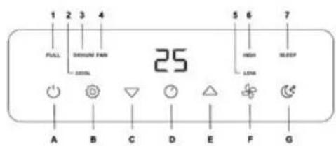
Fig./Img/Abb/Afb/Rys/Obr.3
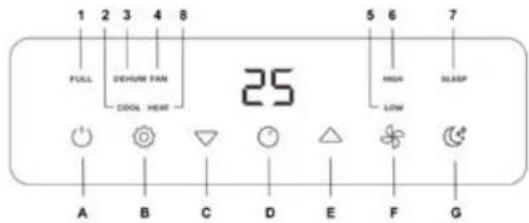
Fig./Img./Abb./Afb./Rys./Obr.S
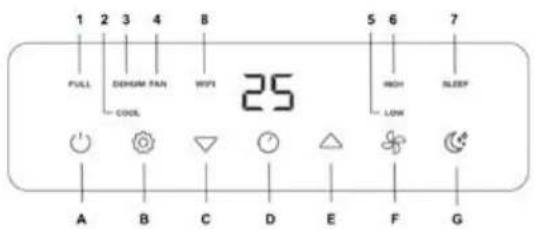
Fig./Img/Abb./Afb/Rys./Obr.4
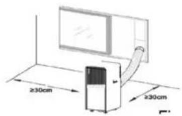
Fig./Img/Abb/Afb/Rys/Obr.10
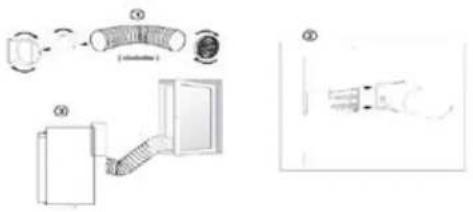
Fig./img./Abb./Afb./Rys./Obr.11
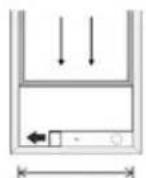
Window width
min:67.5cm
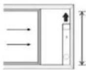
Window height
min:67.5cm
max:123cm
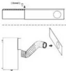
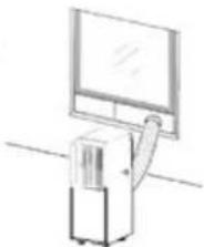
Fig./img/Abb/Afb/Rys/0br.12
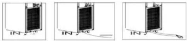
Fig./Img/Abb/Afb/Rys/Obr.13
www.ceotec.es
46910, Alfafar, Spain