USER MANUAL GWS 14-125 CIT BOSCH
Operating instructions
Dr. Egbert Schneider Senior Vice President Engineering
Dr. Eckerhard Strötgen
Head of Product Certification


17.01.2007, Robert Bosch GmbH, Power Tools Division D-70145 Leinfelden-Echterdingen
WARNING Read all safety warnings and all instructions. Failure to follow the
warnings and instructions may result in electric shock, fire and/or serious injury.
Save all warnings and instructions for future reference.
The term "power tool" in the warnings refers to your mains-operated (cored) power tool or battery-operated (cordless) power tool.
1) Work area safety
a) Keep work area clean and well lit. Cluttered or dark areas invite accidents.
b) Do not operate power tools in explosive atmospheres, such as in the presence of flammable liquids, gases or dust. Power tools create sparks which may ignite the dust or fumes.
c) Keep children and bystanders away while operating a power tool. Distractions can cause you to lose control.
2) Electrical safety
a) Power tool plugs must match the outlet. Never modify the plug in any way. Do not use any adapter plugs with earthed (grounded) power tools. Unmodified plugs and matching outlets will reduce risk of electric shock.
b) Avoid body contact with earthed or grounded surfaces, such as pipes, radiators, ranges and refrigerators. There is an increased risk of electric shock if your body is earthed or grounded.
c) Do not expose power tools to rain or wet conditions. Water entering a power tool will increase the risk of electric shock.
d) Do not abuse the cord. Never use the cord for carrying, pulling or unplugging the power tool. Keep cord away from heat, oil, sharp edges and moving parts. Damaged or entangled cords increase the risk of electric shock.
e) When operating a power tool outdoors, use an extension cord suitable for outdoor use. Use of a cord suitable for outdoor use reduces the risk of electric shock.
f) If operating a power tool in a damp location is unavoidable, use a residual current device (RCD) protected supply. Use of an RCD reduces the risk of electric shock.
3) Personal safety
a) Stay alert, watch what you are doing and use common sense when operating a power tool. Do not use a power tool while you are tired or under the influence of drugs, alcohol or medication. A moment of inattention while operating power tools may result in serious personal injury.
b) Use personal protective equipment. Always wear eye protection. Protective equipment such as dust mask, non-skid safety shoes, hard hat, or hearing protection used for appropriate conditions will reduce personal injuries.
c) Prevent unintentional starting. Ensure the switch is in the off-position before connecting to power source and/or battery pack, picking up or carrying the tool. Carrying power tools with your finger on the switch or energising power tools that have the switch on invites accidents.
d) Remove any adjusting key or wrench before turning the power tool on. A wrench or a key left attached to a rotating part of the power tool may result in personal injury.
e) Do not overreach. Keep proper footing and balance at all times. This enables better control of the power tool in unexpected situations.
f) Dress properly. Do not wear loose clothing or jewellery. Keep your hair, clothing and gloves away from moving parts. Loose clothes, jewellery or long hair can be caught in moving parts.
g) If devices are provided for the connection of dust extraction and collection facilities, ensure these are connected and properly used. Use of dust collection can reduce dust-related hazards.
a) Do not force the power tool. Use the correct power tool for your application. The correct power tool will do the job better and safer at the rate for which it was designed.
b) Do not use the power tool if the switch does not turn it on and off. Any power tool that cannot be controlled with the switch is dangerous and must be repaired.
c) Disconnect the plug from the power source and/or the battery pack from the power tool before making any adjustments, changing accessories, or storing power tools. Such preventive safety measures reduce the risk of starting the power tool accidentally.
d) Store idle power tools out of the reach of children and do not allow persons unfamiliar with the power tool or these instructions to operate the power tool. Power tools are dangerous in the hands of untrained users.
e) Maintain power tools. Check for misalignment or binding of moving parts, breakage of parts and any other condition that may affect the power tool's operation. If damaged, have the power tool repaired before use. Many accidents are caused by poorly maintained power tools.
f) Keep cutting tools sharp and clean. Properly maintained cutting tools with sharp cutting edges are less likely to bind and are easier to control.
g) Use the power tool, accessories and tool bits etc. in accordance with these instructions, taking into account the working conditions and the work to be performed. Use of the power tool for operations different from those intended could result in a hazardous situation.
5) Service
a) Have your power tool serviced by a qualified repair person using only identical replacement parts. This will ensure that the safety of the power tool is maintained.
Machine-specific SafetyWarnings
Safety warnings that are common for grinding, sanding, wire brushing or abrasive cutting off operations
This power tool is intended to function as a grinder, sander, wire brush or cut-off tool. Read all safety warnings, instructions, illustrations and specifications provided with this power tool. Failure to follow all instructions listed below may result in electric shock, fire and/or serious injury.
This power tool is not recommended for poslishing. Operations for which the power tool was not designed may create a hazard and cause personal injury.
- Do not use accessories which are not specifically designed and recommended by the tool manufacturer. Just because the accessory can be attached to your power tool, it does not assure safe operation.
The rated speed of the accessory must be at least equal to the maximum speed marked on the power tool. Accessories running faster than their rated speed can fly apart.
The outside diameter and the thickness of your accessory must be within the capacity rating of your power tool. Incorrectly sized accessories cannot be adequately guarded or controlled.
- The arbor size of wheels, flanges, backing pads or any other accessory must properly fit the spindle of the power tool. Accessories with arbor holes that do not match the mounting hardware of the power tool will run out of balance, vibrate excessively and may cause loss of control.
Do not use a damaged accessory. Before each use, inspect the accessory such as abrasive wheels for chips and cracks, backing pads for cracks, tears or excess wear, wire brushes for loose or cracked wires. If power tool or accessory is dropped, inspect for damage or install an undamaged accessory. After inspecting and installing an accessory, position yourself and bystanders away from the plane of the rotating accessory and run the power tool at maximum no-load speed for one minute. Damaged accessories will normally break apart during this test time.
Wear personal protective equipment. Depending on application, use face shield, safety goggles or safety glasses. As appropriate, wear dust mask, hearing protectors, gloves and shop apron capable of stopping small abrasive or workpiece fragments. The eye protection must be capable of stopping flying debris generated by various operations. The dust mask or respirator must be capable of filtrating particles generated by your operation. Prolonged exposure to high intensity noise may cause hearing loss.
- Keep bystanders a safe distance away from the work area. Anyone entering the work area must wear personal protective equipment. Fragments of workpiece or of a broken accessory may fly away and cause injury beyond immediate area of operation.
Hold the power tool only by the insulated gripping surfaces when performing an operation where the cutting tool may contact hidden wiring or its own power cord. Contact with a "live" wire will also make exposed metal parts of the power tool "live" and shock the operator.
Position the cord clear of the spinning accessory. If you lose control of the power tool, the cord may be cut or snagged and your hand or arm may be pulled into the spinning accessory.
- Never lay the power tool down until the accessory has come to a complete stop. The spinning accessory may grab the surface and pull the power tool out of your control.
- Do not run the power tool while carrying it at your side. Accidental contact with the spinning accessory could snag your clothing, pulling the accessory into your body.
Regularly clean the power tool's air vents. The motor's fan will draw the dust inside the housing and excessive accumulation of powdered metal may cause electrical hazards.
Do not operate the power tool near flammable materials. Sparks could ignite these materials.
- Do not use accessories that require liquid coolants. Using water or other liquid coolants may result in electrocution or shock.
- Kickback is a sudden reaction to a pinched or snagged rotating wheel, backing pad, brush or any other accessory. Pinching or snagging causes rapid stalling of the rotating accessory which in turn causes the uncontrolled power tool to be forced in the direction opposite of the accessory's rotation at the point of the binding. For example, if an abrasive wheel is snagged or pinched by the workpiece, the edge of the wheel that is entering into the pinch point can dig into the surface of the material causing the wheel to climb out or kick out. The wheel may either jump toward or away from the operator, depending on direction of the wheel's movement at the point of pinching. Abrasive wheels may also break under these conditions. Kickback is the result of power tool misuse and/or incorrect operating procedures or conditions and can be avoided by taking proper precautions as given below.
- Maintain a firm grip on the power tool and position your body and arm to allow you to resist kickback forces. Always use auxiliary handle, if provided, for maximum control over kickback or torque reaction during start-up. The operator can control torque reactions or kickback forces, if proper precautions are taken.
- Never place your hand near the rotating accessory. The accessory may kickback over your hand.
- Do not position your body in the area where the power tool will move if kickback occurs. Kickback will propel the tool in the direction opposite to the wheel's movement at the point of snagging.
- Use special care when working corners, sharp edges, etc. Avoid bouncing and snagging the accessory. Corners, sharp edges or bouncing have a tendency to snag the rotating accessory and cause loss of control or kickback.
Do not attach a saw chain woodcarving blade or toothed saw blade. Such blades create frequent kickback and loss of control over the power tool.
Additional safety instructions for grinding and cutting off operations
Always use guard designed for the type of wheel you are using. The guard must be securely attached to the power tool and positioned for maximum safety, so the least amount of wheel is exposed towards the operator. The guard helps to protect operator from broken wheel fragments and accidental contact with wheel.
- Use only wheel types that are recommended for your power tool and the specific guard designed for the selected wheel. Wheels for which the power tool was not designed cannot be adequately guarded and are unsafe.
- Wheels must be used only for recommended applications. For example: do not grind with the side of the cut-off wheel. Abrasive cut-off wheels are intended for peripheral grinding; side forces applied to these wheels may cause them to shatter.
Always use undamaged wheel flanges that are of correct size and shape for your selected wheel. Proper wheel flanges support the wheel thus reducing the possibility of wheel breakage. Flanges for cut-off wheels may be different from grinding wheel flanges.
Do not use worn down wheels from larger power tools. Wheels intended for larger power tools are not suitable for the higher speed of a smaller tool and may burst.
Additional safety warnings specific for abrasive cutting off operations
- Do not "jam" the cut-off wheel or apply excessive pressure. Do not attempt to make an excessive depth of cut. Overstressing the wheel increases the loading and susceptibility to twisting or binding of the wheel in the cut and the possibility of kickback or wheel breakage.
Do not position your body in line with and behind the rotating wheel. When the wheel, at the point of operation, is moving away from your body, the possible kickback may propel the spinning wheel and the power tool directly at you.
- When wheel is binding or when interrupting a cut for any reason, switch off the power tool and hold the power tool motionless until the wheel comes to a complete stop. Never attempt to remove the cut-off wheel from the cut while the wheel is in motion, otherwise kickback may occur. Investigate and take corrective action to eliminate the cause of wheel binding.
Do not restart the cutting operation in the workpiece. Let the wheel reach full speed and carefully reenter the cut. The wheel may bind, walk up or kickback if the power tool is restarted in the workpiece.
Support panels or any oversized workpiece to minimize the risk of wheel pinching and kickback. Large workpieces tend to sag under their own weight. Supports must be placed under the workpiece near the line of cut and near the edge of the workpiece on both sides of the wheel.
- Use extra caution when making a "pocket cut" into existing walls or other blind areas. The protruding wheel may cut gas or water pipes, electrical wiring or objects that can cause kickback.
Safety warnings specific for sanding operations
- When sanding, do not use excessively oversized sanding disc paper. Follow manufacturers recommendations, when selecting sanding paper. Larger sanding paper extending beyond the sanding pad presents a laceration hazard and may cause snagging, tearing of the disc, or kickback.
Safety warnings specific for wire brushing operations
- Be aware that wire bristles are thrown by the brush even during ordinary operation. Do not overstress the wires by applying excessive load to the brush. The wire bristles can easily penetrate light clothing and/or skin.
If the use of a guard is recommended for wire brushing, do not allow any interference of the wire wheel or brush with the guard. Wire wheel or brush may expand in diameter due to work load and centrifugal forces.
Additional safety warnings

Wear safety goggles.
-
Use suitable detectors to determine if utility lines are hidden in the work area or call the local utility company for assistance. Contact with electric lines can lead to fire and electric shock. Damaging a gas line can lead to explosion. Penetrating a water line causes property damage or may cause an electric shock.
Always use the protective devices specified for the respective applicational case. Protective devices not suitable for the applicational case cannot cover off the grinding tool sufficiently.
-
When working stone, use dust extraction. The vacuum cleaner must be approved for the extraction of stone dust. Using this equipment reduces dust-related hazards.
Use a cutting guide when cutting stone. Without sideward guidance, the cutting disc can jam and cause kickback.
- When working with the machine, always hold it firmly with both hands and provide for a secure stance. The power tool is guided more secure with both hands.
- Secure the workpiece. A workpiece clamped with clamping devices or in a vice is held more secure than by hand.
Do not work materials containing asbestos. Asbestos is considered carcinogenic.
Take protective measures when dust can develop during working that is harmful to one's health, combustible or explosive. Example: Some dusts are regarded as carcinogenic. Wear a dust mask and work with dust/chip extraction when connectable.
- Keep your workplace clean. Blends of materials are particularly dangerous. Dust from light alloys can burn or explode.
- Never use the machine with a damaged cable. Do not touch the damaged cable and pull the mains plug when the cable is damaged while working. Damaged cables increase the risk of an electric shock.
Functional Description

Read all safety warnings and all instructions. Failure to follow the warnings and instructions may result in electric shock, fire and/or serious injury.
While reading the operating instructions, unfold the graphics page for the machine and leave it open.
Intended Use
The machine is intended for cutting, roughing, and brushing metal and stone materials without using water.
For cutting metal, a special protection guard for cutting (accessory) must be used.
For cutting stone, a special extraction hood for cutting with cutting guide (accessory) must be used.
With approved sanding tools, the machine can be used for sanding with sanding discs.
Technical Data
| Angle Grinder | GWS ...
PROFESSIONAL | 8-115 | 8-125 | 10-125 | 11-125
CI | 11-125
CIE |
| Article number | 3 601 ... | H20 ... | H27 ... | H21 ... | H22 ... | H23 ... |
| Rated power input | W | 800 | 800 | 1000 | 1100 | 1100 |
| Output power | W | 500 | 500 | 630 | 660 | 660 |
| No-load speed | rpm | 11000 | 11000 | 11000 | 11000 | 2800
-11000 |
| Grinding disc diameter, max. | mm | 115 | 125 | 125 | 125 | 125 |
| Thread of grinder spindle | | M 14 | M 14 | M 14 | M 14 | M 14 |
| Kickback stop | | - | - | - | ● | ● |
| Restarting protection | | - | - | - | ● | ● |
| Reduced starting current | | - | - | - | ● | ● |
| Constant electronic control | | - | - | - | ● | ● |
| Speed preselection | | - | - | - | - | ● |
| Weight according to
EPTA-Procedure 01/2003 | kg | 1.9 | 1.9 | 2.1 | 2.0 | 2.0 |
| Protection class | | □/II | □/II | □/II | □/II | □/II |
The values given are valid for nominal voltages [U] of 230/240 V. For lower voltage and models for specific countries, these values can vary.
Please observe the article number on the type plate of your machine. The trade names of the individual machines may vary.
| Angle Grinder | GWS ...
PROFESSIONAL | 14-125
CI | 14-125
CIE | 14-125
CIT | 14-150
CI |
| Article number | 3 601 ... | H24 ... | H25 ... | H29 ... | H26 ... |
| Rated power input | W | 1400 | 1400 | 1400 | 1400 |
| Output power | W | 820 | 820 | 820 | 820 |
| No-load speed | rpm | 11000 | 2800 | 2800 | 9300 |
| -11000 | -9300 |
| Grinding disc diameter, max. | mm | 125 | 125 | 125 | 150 |
| Thread of grinder spindle | | M 14 | M 14 | M 14 | M 14 |
| Kickback stop | | ● | ● | ● | ● |
| Restarting protection | | ● | ● | ● | ● |
| Reduced starting current | | ● | ● | ● | ● |
| Constant electronic control | | ● | ● | ● | ● |
| Speed preselection | | - | ● | ● | - |
| Weight according to EPTA-Procedure | | | | | |
| 01/2003 | kg | 2.2 | 2.2 | 2.2 | 2.3 |
| Protection class | | ☐/II | ☐/II | ☐/II | ☐/II |
The values given are valid for nominal voltages [U] of 230/240 V. For lower voltage and models for specific countries, these values can vary.
Please observe the article number on the type plate of your machine. The trade names of the individual machines may vary.
Product Features
The numbering of the product features refers to the illustration of the machine on the graphics page.
1 Release lever for protection guard
2 Spindle lock button
3 Thumbwheel for speed preselection (GWS 11-125 CIE/GWS 14-125 CIE/ GWS 14-125 CIT)
4 On/Off switch
5 Auxiliary handle
6Grinder spindle
7 Extraction hood for sanding
8 Mounting flange with O-ring
9 Carbide grinding head
10 Clamping nut
11 Quick-clamping nut SDS-clip
12 Protection guard for sanding
13 Protection guard for cutting
14 Grinding/cutting disc
15 Hand guard
16 Rubber sanding plate*
17 Sanding sheet
18 Round nut*
19 Cup brush
20 Cutting guide with dust extraction protection guard
21 Diamond cutting disc
*The accessories illustrated or described are not included as standard delivery.
We declare under our sole responsibility that this product is in conformity with the following standards or standardization documents: EN 60745 according to the provisions of the directives 89/336/EEC, 98/37/EC.
Dr. Egbert Schneider
Dr. Eckerhard Strötgen
Senior Vice President
Head of Product
Engineering
Certification
ppa. Muee i.v. uogcu
17.01.2007, Robert Bosch GmbH, Power Tools Division D-70145 Leinfelden-Echterdingen
Noise/Vibration Information
| Measured values determined according to EN 60745. | 3 601 ... | H20 ... | H22 ... | H29 ... |
| H27 ... | H23 ... |
| H21 ... | H24 ... |
| H25 ... |
| H26 ... |
| Typically the A-weighted noise level of the machine is: | | | | |
| sound pressure level | dB(A) | 91 | 91 | 91 |
| sound power level | dB(A) | 102 | 102 | 102 |
| Uncertainty K= | dB | 3 | 3 | 3 |
| Wear hearing protection! | | | | |
| Overall vibrational value (vector sum of three directions) determined according to EN 60745: | | | | |
| Grinding surfaces (roughing): | | | | |
| Vibrational emission value ah | m/s2 | 5.5 | 8.5 | 7.0 |
| uncertainty K= | m/s2 | 2.0 | 2.0 | 2.0 |
| Sanding with sanding discs: | | | | |
| Vibrational emission value ah | m/s2 | 3.0 | 3.0 | 3.0 |
| uncertainty K= | m/s2 | 1.5 | 1.5 | 1.5 |
The vibration emission level given in this information sheet has been measured in accordance with a standardised test given in EN 60745 and may be used to compare one tool with another.
The vibration emission level will vary because of the ways in which a power tool can be used and may increase above the level given in this information sheet. This could lead to a significant underestimate of exposure when the tool is used regularly in such a way.
Note: To be accurate, an estimation of the level of exposure to vibration experienced during a given period of work should also take into account the times when the tool is switched off and when it is running but not actually doing the job. This may significantly reduce the exposure level over the total working period.
Assembly
Mounting the Protective Devices
Before any work on the machine itself, pull the mains plug.
Protection Guard for Sanding
Place the protection guard 12 onto the spindle collar as shown in the illustration. The triangle marks on the protection guard must correspond with the respective marks on the gear case.
Press the protection guard 12 onto the spindle collar until the shoulder of the protection guard is seated against the flange of the machine, and turn the protection guard until it can clearly be heard to engage.
Adjust the position of the protection guard 12 to the requirements of the work process. For this, press the release lever 1 upward and turn the protection guard 12 to the required position.
Adjust the protection guard 12 in such a manner that sparking is prevented in the direction of the operator.
The protection guard 12 may be turned only upon actuation of the release lever 1! Otherwise the power tool may not continue to be used under any circumstances and must be taken to an after-sales service agent.
Note: The encoding keys on the protection guard 12 ensure that only a protection guard that fits the machine type can be mounted.
Protection Guard for Cutting
For cutting metal, always work with the protection guard for cutting 13.
For cutting stone, always work with the cutting guide with dust extraction protection guard 20.
The protection guard for cutting 13 is mounted in the same manner as the protection guard for sanding 12.
Extraction Hood for Sanding
The extraction hood 7 can be used for low-dust sand- ing of paint, varnish and plastics in conjunction with the carbide grinding head 9 or the rubber sanding plate 16 with a sanding sheet 17. The extraction hood 7 is not suitable for working metals.
A suitable Bosch vacuum cleaner can be connected to the extraction hood 7.
The extraction hood 7 is mounted in the same manner as the protection guard 12. The brush collar is exchangeable.
Auxiliary Handle
Operate your machine only with the auxiliary handle 5.
Screw the auxiliary handle 5 on the right or left of the machine head depending on the working method.
Vibration-dampening Auxiliary Handle
Vibration Control
The vibration-dampening auxiliary handle reduces the vibrations, making operation more comfortable and secure.
Do not make any alterations to the auxiliary handle.
Do not continue to use an auxiliary handle if it is damaged.
Hand Guard
For operations with the rubber sanding plate 16 or with the cup brush/wheel brush/flap disc, always mount the hand guard 15.
The hand guard 15 is fastened with the auxiliary handle 5.
Before any work on the machine itself, pull the mains plug.
Grinding and cutting discs become very hot while working; do not touch until they have cooled.
Clean the grinder spindle 6 and all parts to be mounted.
For clamping and loosening the grinding tools, lock the grinder spindle with the spindle lock button 2.
- Actuate the spindle lock button only when the grinder spindle is at a standstill. Otherwise, the machine may become damaged.
Grinding/Cutting Disc
Pay attention to the dimensions of the grinding tools. The mounting hole diameter must fit the mounting flange without play. Do not use reducers or adapters.
When using diamond cutting discs, pay attention that the direction-of-rotation arrow on the diamond cutting disc and the direction of rotation of the machine (see direction-of-rotation arrow on the machine head) agree.
See graphics page for the mounting sequence.
To fasten the grinding/cutting disc, screw on the clamping nut 10 and tighten with the two-pin spanner; see Section "Quick-clamping Nut".
After mounting the grinding tool and before switching on, check that the grinding tool is correctly mounted and that it can turn freely. Make sure that the grinding tool does not graze against the protection guard or other parts.
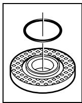
An O-ring (plastic part) is inserted in the mounting flange 8 around the centring collar. If the O-ring is missing or is damaged, it must in all cases be replaced (article number 1600210039) before the mounting flange 8 is mounted.
Flap Disc
For operations with the rubber sanding plate 16 or with the cup brush/wheel brush/flap disc, always mount the hand guard 15.
Rubber Sanding Plate
For operations with the rubber sanding plate 16 or with the cup brush/wheel brush/flap disc, always mount the hand guard 15.
See graphics page for the mounting sequence.
Screw on the round nut 18 and tighten with the two-pin spanner.
Cup Brush/Disc Brush
For operations with the rubber sanding plate 16 or with the cup brush/wheel brush/flap disc, always mount the hand guard 15.
See graphics page for the mounting sequence.
The cup brush/disc brush must be able to be screwed onto the grinder spindle until it rests firmly against the grinder spindle flange at the end of the grinder spindle threads. Tighten the cup brush/disc brush with an open-end spanner.
Quick-clamping Nut SDS-clic
For convenient changing of grinding tools without the use of additional tools, you can use the quick-clamping nut 11 instead of the clamping nut 10.
The quick-clamping nut 11 may be used only for grinding or cutting discs.
Use only a flawless, undamaged quick-clamping nut 11.
When screwing on, pay attention that the side of the quick-clamping nut 11 with printing does not face the grinding disc; the arrow must point to the index mark 22.
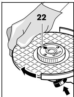
Lock the grinder spindle with the spindle lock button 2. To tighten the quickclamping nut, firmly turn the grinding disc in clockwise direction.
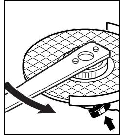
A properly attached, undamaged quick-clamping nut can be loosened by hand when turning the knurled ring in anticlockwise direction.
Never loosen a tight quick-clamping nut with pliers. Always use the two-pin spanner. Insert the two-pin spanner as shown in the illustration.
All grinding tools mentioned in these operating instructions can be used.
The permissible speed [rpm] or the circumferential speed [m / s] of the grinding tools used must at least match the values given in the table.
Therefore, observe the permissible rotational/circumferential speed on the label of the grinding tool.
| max. [mm] | [mm] | [rpm] | [m/s] |
| D | b | d |
| b d | 115 | 6 | 22.2 | 11000 | 80 |
| 125 | 6 | 22.2 | 11000 | 80 |
| 150 | 6 | 22.2 | 9300 | 80 |
| D | 115 | - | - | 11000 | 80 |
| 125 | 11000 | 80 |
| b d D | 75 | 30 | M 14 | 11000 | 45 |
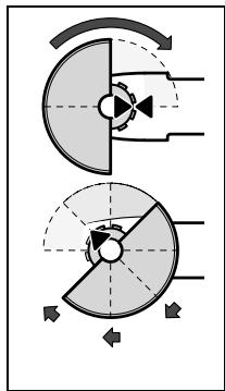
Rotating the Machine Head
Before any work on the machine itself, pull the mains plug.
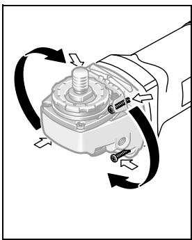
The machine head can be rotated with respect to the machine housing in 90^ steps. In this manner, the On/Off switch can be brought into a more convenient position for special working situations, e.g., for cutting operations using the cutting guide with dust extraction protection guard 20/cut off stand or for left-handed persons.
Completely unscrew the four screws. Rotate the machine head carefully, without removing it from the housing, to the new position. Screw in and tighten the four screws again.
Operation
Starting Operation
Observe correct mains voltage! The voltage of the power source must agree with the voltage specified on the nameplate of the machine. Power tools marked with 230V can also be operated with 220V .
When operating the machine with power from mobile generators that do not have sufficient reserve capacity or are not equipped with suitable voltage control with starting current amplification, loss of performance or untypical behavior can occur upon switching on.
Please observe the suitability of the power generator being used.
Switching On and Off
To start the power tool, push the On/Off switch 4 forwards.
To lock the On/Off switch 4, press the On/Off switch 4 down at the front until it latches.
To switch off the power tool, release the On/Off switch 4 or, if it is locked, briefly push down the back of the On/Off switch 4 and then release it.
- Check grinding tools before using. The grinding tool must be mounted properly and be able to move freely. Carry out a test run for at least one minute with no load. Do not use damaged, out-of-centre or vibrating grinding tools. Damaged grinding tools can burst and cause injuries.
Kickback stop
(GWS 11-125 CI/GWS 11-125 CIE/
GWS 14-125 CI/GWS 14-125 CIE/
GWS 14-125 CIT/GWS 14-150 CI)

In case of a sudden drop in speed, e. g. jamming while carrying out a separating cut, the power supply to the motor is interrupted.
To restart the operation, switch the On/Off switch 4 to the Off position and start the machine again.
Restarting protection
(GWS 11-125 CI/GWS 11-125 CIE/
GWS 14-125 CI/GWS 14-125 CIE/
GWS 14-125 CIT/GWS 14-150 CI
The restarting protection feature prevents uncontrolled restarting of the machine after an interruption in the power supply.
To restart the operation, switch the On/Off switch
4 to the Off position and start the machine again.
Reduced starting current
(GWS 11-125 CI/GWS 11-125 CIE/
GWS 14-125 CI/GWS 14-125 CIE/
GWS 14-125 CIT/GWS 14-150 CI)
The electronic reduced starting current limits the power consumption when switching the tool on and enables operation from a 13 ampere fuse.
Constant Electronic Control
(GWS 11-125 CI/GWS 11-125 CIE/
GWS 14-125 CI/GWS 14-125 CIE/
GWS 14-125 CIT/GWS 14-150 CI
Constant electronic control holds the speed constant at no-load and under load, and ensures uniform working performance.
Speed preselection (GWS 11-125 CIE/GWS 14-125 CIE/GWS 14-125 CIT)
The required speed can be preselected with the thumbwheel 3 (also while running).
The data in the following table are recommended values.
| Material | Application | Tool | Thumbwheel 3 |
| Metal | Removing paint | Sanding disc | 2 – 3 |
| Wood, metall | Brushing, rust removal | Cup brush, sanding disc | 3 |
| Metal, masonry | Sanding | Sanding disc | 4 – 6 |
| Metal | Rough grinding | Sanding disc | 6 |
| Masonry, stone | Cutting | Cutting disc and cutting guide (Cutting masonry/stone is permitted only with use of the cutting guide) | 6 |
Operating Instructions
Exercise caution when cutting slots in structural walls; see Section "Information on Structures".
- Clamp the workpiece if it does not remain stationary due to its own weight.
Do not strain the machine so heavily that it comes to a standstill.
Grinding and cutting discs become very hot while working; do not touch until they have cooled.
Rough Grinding
Never use a cutting disc for roughing.
The best roughing results are achieved when setting the machine at an angle of 30^ to 40^ . Move the machine back and forth with moderate pressure. In this manner, the workpiece will not become too hot, does not discolour and no grooves are formed.
Flap Disc
With the flap disc (accessory), curved surfaces and profiles can be worked.
Flap discs have a considerably higher service life, lower noise levels and lower sanding temperatures than conventional sanding sheets.
For cutting metal, always work with the protection guard for cutting 13.
When cutting, work with moderate feed, adapted to the material being cut. Do not exert pressure onto the cutting disc, tilt or oscillate the machine.
Do not reduce the speed of running down cutting discs by applying sideward pressure.
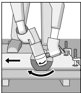
The machine must always work in an upgrinding motion. Otherwise, the danger exists of it being pushed uncontrolled out of the cut.
When cutting profiles and square bar, it is best to start at the smallest cross section.
Cutting Stone
For cutting stone, always work with the cutting guide with dust extraction protection guard 20.
The machine may be used only for dry cutting/grinding.
For cutting stone, it is best to use a diamond cutting disc. As a safety measure against jamming, the cutting guide with dust extraction protection guard 20 must be used. Operate the machine only with dust extraction and additionally wear a dust protection mask.
The vacuum cleaner must be approved for the extraction of masonry dust. Bosch provides suitable vacuum cleaners.
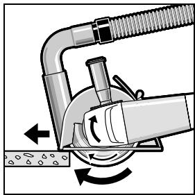
Switch on the machine and place the front part of the cutting guide on the workpiece. Slide the machine with moderate feed, adapted to the material to be worked.
For cutting especially hard material, e. g., concrete with high pebble content, the diamond cutting disc can overheat and become damaged as a result. This is clearly indicated by circular sparking, rotating with the diamond cutting disc.
In this case, interrupt the cutting process and allow the diamond cutting disc to cool by running the machine for a short time at maximum speed with no load.
Noticeable decreasing work progress and circular sparking are indications of a diamond cutting disc that has become dull. Briefly cutting into abrasive material (e.g. lime-sand brick) can resharpen the disc again.
Slots in structural walls are subject to the Standard DIN 1053 Part 1, or country-specific regulations.
These regulations are to be observed under all circumstances. Before beginning work, consult the responsible structural engineer, architect or the construction supervisor.
Maintenance and Service
Maintenance and Cleaning
Before any work on the machine itself, pull the mains plug.
For safe and proper working, always keep the machine and ventilation slots clean.
In extreme working conditions, conductive dust can accumulate in the interior of the machine when working with metal. The protective insulation of the machine can be degraded. The use of a stationary extraction system is recommended in such cases as well as frequently blowing out the ventilation slots and installing a residual current device (RCD).
If the machine should fail despite the care taken in manufacturing and testing procedures, repair should be carried out by an after-sales service centre for Bosch power tools.
In all correspondence and spare parts order, please always include the 10-digit article number given on the type plate of the machine.
WARNING! Important instructions for connecting a new 3-pin plug to the 2-wire cable.
The wires in the cable are coloured according to the following code:

Do not connect the blue or brown wire to the earth terminal of the plug.
Important: If for any reason the moulded plug is removed from the cable of this power tool, it must be disposed of safely.
Service and Customer Assistance
Exploded views and information on spare parts can be found under:
www.bosch-pt.com
Great Britain
Robert Bosch Ltd. (B.S.C.)
P.O.Box 98
Broadwater Park
North Orbital Road
Denham-Uxbridge
Middlesex UB 9 5HJ
Service: +44 (0) 18 95 / 83 87 82
(2) Advice line: +44 (0) 1895 / 838791
Fax: +44 (0) 1895 / 838789
Ireland
Origo Ltd.
Unit 23 Magna Drive
Magna Business Park
City West
Dublin 24
Service: +353 (0)1 / 4666700
Fax: +353 (0)1 / 4666888
Australia and New Zealand
Robert Bosch Australia Pty. Ltd.
RBAU/SPT
1555 Centre Road
P.O.Box 66
3168 Clayton/Victoria
+61(0)1/300307044
Fax: +61 (0)1 / 300307045
www.bosch.com.au
Disposal
The machine, accessories and packaging should be sorted for environmental-friendly recycling.
Only for EC countries:
Do not dispose of power tools into household waste!
According the European Guideline 2002/96/EC for Waste Electrical and Electronic Equipment and its implementation into national right, power
tools that are no longer usable must be collected separately and disposed of in an environmentally correct manner.
Subject to change without notice.
Dr. Egbert Schneider Senior Vice President Engineering
Dr. Eckerhard Strötgen
Head of Product Certification
ppa. /mea/ i.v. nuogcu
17.01.2007, Robert Bosch GmbH, Power Tools Division D-70145 Leinfelden-Echterdingen
Robert Bosch France S.A.S.
Dr. Egbert Schneider Senior Vice President Engineering
Dr. Eckerhard Strötgen
Head of Product Certification


17.01.2007, Robert Bosch GmbH, Power Tools Division D-70145 Leinfelden-Echterdingen
Senior Vice President
Engineering
Dr. Eckerhard Strötgen
Head of Product
Certification


17.01.2007, Robert Bosch GmbH, Power Tools Division
D-70145 Leinfelden-Echterdingen
Senior Vice President
Head of Product
Engineering
Certification


17.01.2007, Robert Bosch GmbH, Power Tools Division D-70145 Leinfelden-Echterdingen
Senior Vice President
Engineering
Dr. Eckerhard Strötgen
Head of Product
Certification

17.01.2007, Robert Bosch GmbH, Power Tools Division
D-70145 Leinfelden-Echterdingen
Snelspanmoer SDS-clic
Dr. Egbert Schneider Senior Vice President Engineering
Dr. Eckerhard Strötgen
Head of Product Certification


17.01.2007, Robert Bosch GmbH, Power Tools Division D-70145 Leinfelden-Echterdingen
Senior Vice President
Engineering
Dr. Eckerhard Strötgen
Head of Product
Certification


17.01.2007, Robert Bosch GmbH, Power Tools Division
D-70145 Leinfelden-Echterdingen
Buller-/vibrationsdata
Senior Vice President
Engineering
Dr. Eckerhard Strötgen
Head of Product
Certification
ppa. 11. i.v. uogcu
17.01.2007, Robert Bosch GmbH, Power Tools Division
D-70145 Leinfelden-Echterdingen
Dr. Egbert Schneider Senior Vice President Engineering
Dr. Eckerhard Strötgen
Head of Product Certification

17.01.2007, Robert Bosch GmbH, Power Tools Division D-70145 Leinfelden-Echterdingen
Melu-/tärinatiedot
EviKec pOeIbOIOINTiKec unoBcEic yia nAekTpiKa εpyaλεia
A IPOEIADOTOIH-EN
AiaaTe oaes TIC npoEiDOnoiTikec unodieEic.
AeieKata TnV npon Twv npoeiOo nntikov unobeiEevu npoei va poka eouv nektponlEia, kivduvo npkayiac /kai obaouc tpaumatouc.
Dr. Egbert Schneider Senior Vice President Engineering
Dr. Eckerhard Strötgen
Head of Product Certification


17.01.2007, Robert Bosch GmbH, Power Tools Division D-70145 Leinfelden-Echterdingen
Móvo yia xwpeC tnc EE:
Mny pixvETa nIeKtpiKa epyaia Ota anoppmuata Tou ottiou oac!
Senior Vice President
Engineering
Dr. Eckerhard Strötgen
Head of Product
Certification


17.01.2007, Robert Bosch GmbH, Power Tools Division D-70145 Leinfelden-Echterdingen
Bosch San. ve Tic. A.S.
Ahi Evran Cad. No:1 Kat:22
Polaris Plaza
80670 Maslak/Istanbul
Müsteri Danismani: . . . . . . +90 (0)2 12 / 3 35 06 66
Müsteri Servis Hatti: .+90 (0)2 12 / 3 35 07 52
Tasfiye
Power Tools Division
70745 Leinfelden-Echterdingen
www.bosch-pt.com
1609929L00(2007.02)O/165