
PerfectView RVS 745 - Rear Camera DOMETIC - Free user manual and instructions
Find the device manual for free PerfectView RVS 745 DOMETIC in PDF.

| Brand | Dometic |
| Model | PerfectView RVS 745 (M7LS screen) |
| Product type | Rear view camera with LCD screen |
| Screen size | 7 inches (17.8 cm) |
| Screen resolution | 337 000 pixels (H x V) |
| Brightness | Approx. 300 cd/m² |
| Operating voltage | 11 - 16 V |
| Max power | 8 W |
| Dimensions (W x H x D) | 170 x 125 x 25 mm |
| Weight | 400 g |
| Operating temperature | -20 °C to +65 °C |
| Storage temperature | -25 °C to +80 °C |
| Max humidity | 85 % |
| Vibration resistance | 5 g |
| Certifications | CE, automotive compliance |
| Main functions | Switching between 2 cameras, mirror function, brightness/contrast/color settings, automatic brightness adaptation, illuminated buttons, automatic on/off with reverse light |
| Maintenance and cleaning | Clean with a damp cloth, do not use sharp objects, disconnect before cleaning |
| Safety | Do not mount in airbag deployment zone, fasten securely, avoid contact with water, do not open the screen |
| Included parts | Screen, bracket, connection cable, mounting hardware |
| Repairability | Legal warranty, contact manufacturer or authorized dealer |
Frequently Asked Questions - PerfectView RVS 745 DOMETIC
User questions about PerfectView RVS 745 DOMETIC
0 question about this device. Answer the ones you know or ask your own.
Ask a new question about this device
Download the instructions for your Rear Camera in PDF format for free! Find your manual PerfectView RVS 745 - DOMETIC and take your electronic device back in hand. On this page are published all the documents necessary for the use of your device. PerfectView RVS 745 by DOMETIC.
USER MANUAL PerfectView RVS 745 DOMETIC
natural_image
Line drawing of a rectangular electronic device with labeled buttons (no text or symbols beyond basic labels)M7LS
EN
LCD-Monitor
Installation and Operating Manual ..... 11
DE
LCD-Monitor
natural_image
Technical diagram showing a welding process with two crossed lines and arrows indicating motion (no text or symbols)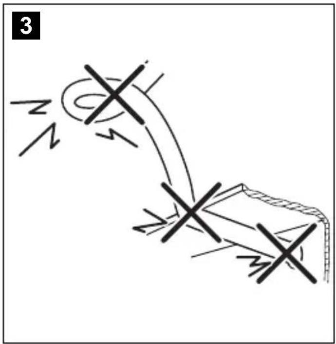
natural_image
Illustration of a hand using a tool to cut a device with a diagonal line crossing it, no text or symbols present.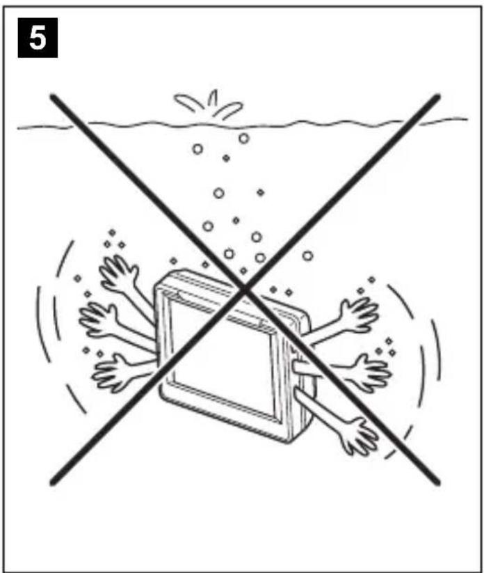
natural_image
Illustration of a book with hands reaching out of water, no text or symbols present6
A
natural_image
Line drawing of two hands holding a small mechanical component (no text or symbols)C
natural_image
Line drawing of a hand holding a mechanical component with a spring-like spring attached (no text or symbols)B
natural_image
Line drawing of two hands holding a tool or connector (no text or symbols present)D

natural_image
Line drawing of two hands holding a small electronic component (no text or symbols)7
A
8
A
B
B
C
natural_image
Diagram of a rope being inserted into a coiled spring, showing rope routing and wire connection (no text or symbols)C
natural_image
Illustration of a rope knot being tied with a coiled wire, showing rope routing and cable attachment (no text or symbols)D
natural_image
Simple line drawing of a coiled cable or tube with no text or symbolsD

natural_image
Line drawing of a person sitting in a chair with a steering wheel, showing light rays projecting onto the seat (no text or symbols)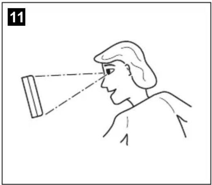
natural_image
Line drawing of a person observing through a lens, showing light rays and focal point (no text or symbols)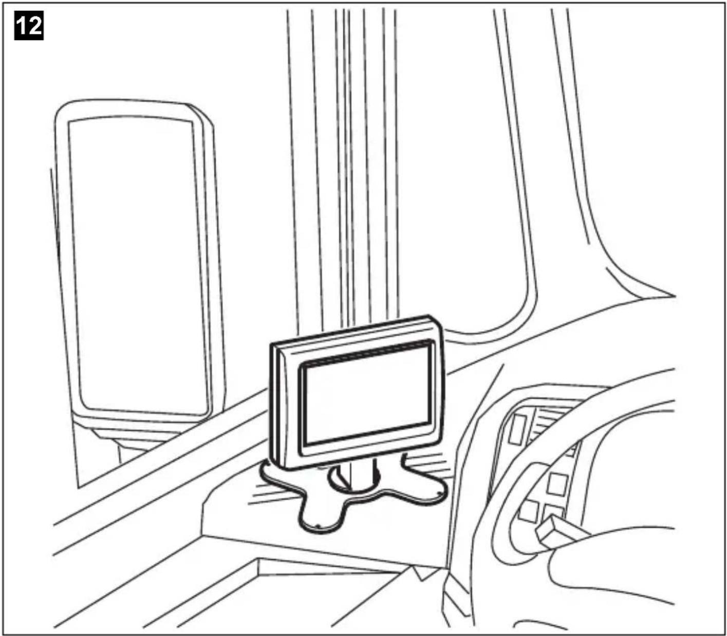
natural_image
Line drawing of a car interior showing a monitor, seatbelt, and dashboard (no text or symbols)13
14
15
16
Please read this instruction manual carefully before installation and first use, and store it in a safe place. If you pass on the product to another person, hand over this instruction manual along with it.
Contents
1 Notes on using the operating manual.... 11
2 Safety and installation instructions....12
3 Scope of delivery 14
4 Intended use....14
5 Technical description....15
6 General information on the electrical connections....16
7 Mounting the monitor 17
8 Using the LCD-monitor....21
9 Cleaning and maintaining the LCD monitor 23
10 Guarantee....23
11 Disposal....23
12 Technical data....24
1 Notes on using the operating manual

CAUTION!
Safety instruction: Failure to observe this instruction can lead to injury.

NOTICE!
Failure to observe this instruction can cause material damage and impair the function of the product.

NOTE
Supplementary information for operating the product.
2 Safety and installation instructions
Please observe the prescribed safety instructions and stipulations from the vehicle manufacturer and service workshops.
The manufacturer accepts no liability for damage in the following cases:
• Faulty assembly or connection
- Damage to the product resulting from mechanical influences and excess voltage
• Alterations to the product without express permission from the manufacturer
- Use for purposes other than those described in the operating manual

NOTICE! Beware of damage
- To prevent the risk of short circuits, always disconnect the negative terminal of the vehicle's electrical system before working on it. If the vehicle has an additional battery, its negative terminal should also be disconnected.
- Inadequate supply cable connections could result in short circuits, causing:
- Cable fires
– The airbag being triggered
– Damage to electronic control equipment
– Electrical malfunctions (indicators, brake light, horn, ignition, lights)
Therefore, please observe the following instructions:
- When working on the following cables, only use insulated cable terminals, plugs and flat sockets:
- 30 (direct supply from positive battery terminal)
- 1 5 ( connected positive terminal, behind the battery)
- 31 (return cable from the battery, earth)
- Reversing light
Do not use porcelain wire connectors.
- Use a crimping tool (fig. 1 12, page 3) to connect the cables.
- Screw the cable when connecting cable 31 (earth)
- Screw on the cable using a cable terminal and serrated washer to one of the vehicle's earth bolts or
- Screw the cable to the bodywork using a cable terminal and a self-tapping screw
Make sure there is a good earth connection.
If you disconnect the negative terminal of the battery, all data stored in the volatile memories will be lost.
- The following data must be reset, depending on the vehicle equipment options:
- Radio code
- Vehicle clock
- Timer
- On-board computer
- Seat position
You can find instructions for making these settings in the operating manual.
Observe the following installation instructions:

CAUTION!
- Secure the monitor in such a way that it cannot become loose under any circumstances (sudden braking, accidents) and cause injuries to the occupants of the vehicle.
- Do not attach the monitor in the air bag deployment path, as this could cause injury if the airbags are triggered.
Observe the following instructions when working with electrical parts:
-
When testing the voltage in electrical cables, only use a diode test lamp (fig. 1 1, page 3) or a voltmeter (fig. 1 2, page 3).
Test lamps with a bulb (fig. 1 3, page 3) consume excessive current which can damage the vehicle's electronic system. -
When making electrical connections, ensure that:
– they are not kinked or twisted
– they do not rub on edges
– they are not laid in sharp-edged ducts without protection (fig. 3, page 4).
• Insulate all connections.
- Secure the cables against mechanical wear by using cable binders or insulating tape, for example on existing cables.
Observe the following instructions when handling the LCD monitor:

CAUTION!
- People (including children) whose physical, sensory or mental capacities or lack of experience or knowledge prevent them from using this product safely should not use it without the supervision or instruction of a responsible person.
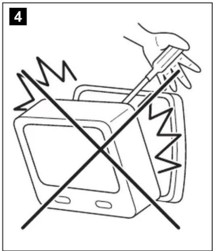
- Do not open the monitor (fig. 4, page 4).
- Do not immerse the monitor in water (fig. 5, page 4); the monitor is not waterproof.
- The monitor must not impair your vision when driving (fig. 12, page 7).
- Do not operate the monitor with wet hands.
- Do not operate the monitor if the housing has been damaged.

NOTICE!
- Connect it to the correct voltage.
- Do not use the monitor in areas which
– Are subjected to direct sunlight,
– Have high levels of humidity, - Are poorly ventilated,
- Are dusty or oily.
– Are subject to strong temperature fluctuations,
- Do not press against the LCD display.
- Do not drop the monitor.
- If you use the monitor in vehicles, the vehicle should be running during operation to prevent the vehicle battery from discharging.
- The picture quality can be impaired in the vicinity of electromagnetic fields. For this reason do not mount the monitor near loudspeakers.
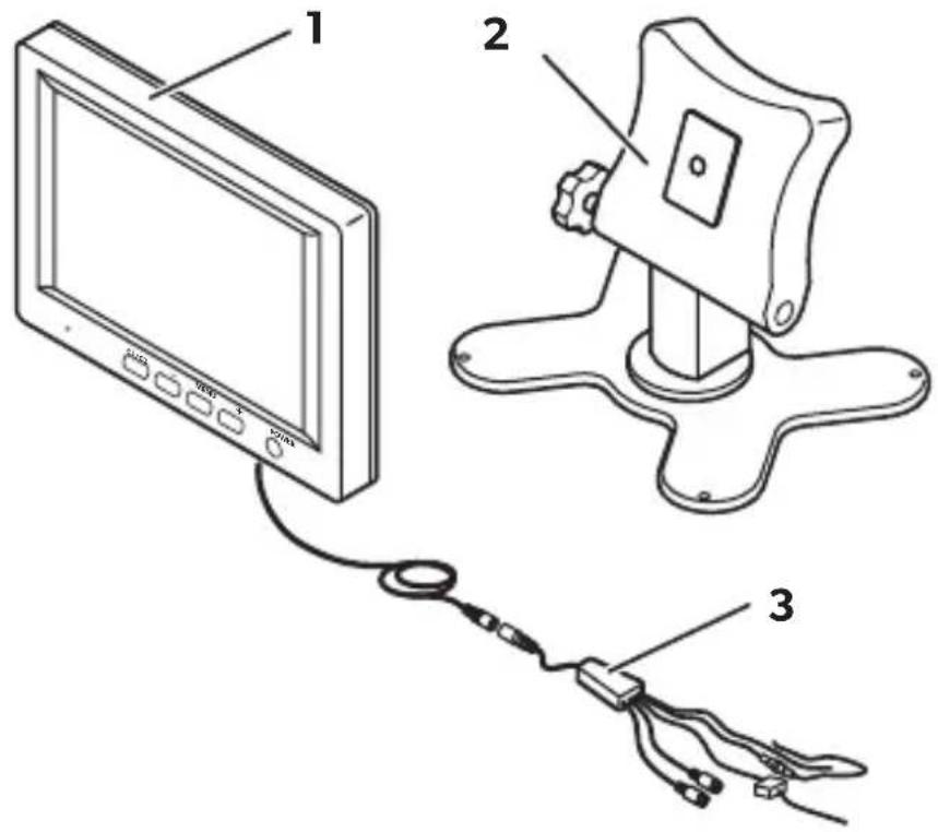
3 S c o p e o f d e l
| No. in fig. 13, page 8 | Quantity Description | Reference number | |||
| 11 Monitor M7LS 9600000204 | |||||
| 2 | 1 | M | o | n | i |
| 3 | 1 Connection cable | 9102200027 | |||
| - | - | F | a | s | t |
4 l n t e n d e d u s
The M7LS LCD monitor (item no. 9600000204) is a monitor primarily intended for use in vehicles. It can be used to connect cameras (e.g. a reversing video system) or other video sources.
The LCD monitor is designed for use in all vehicles.
Since rear view systems are designed merely as an additional aid for reversing, it does not relieve you of the duty to take proper care when reversing.
5 Technical description
5.1 Function description
The LCD monitor is a monitor which allows cameras (e.g. a rear view video camera) or other video sources (e.g. a TV) to be connected. It is possible to switch back and forth between video sources.
The monitor can be mounted on the dashboard, where it transmits the image from the connected camera, allowing the driver to see the area behind the vehicle, e. g. when parking.
The brightness of the monitor adapts automatically to the ambient light.
The buttons are illuminated and can therefore also be operated in the dark.
The mirrored picture function can be activated individually for each of the two video inputs. The image then appears as if you were looking into the rear view mirror.
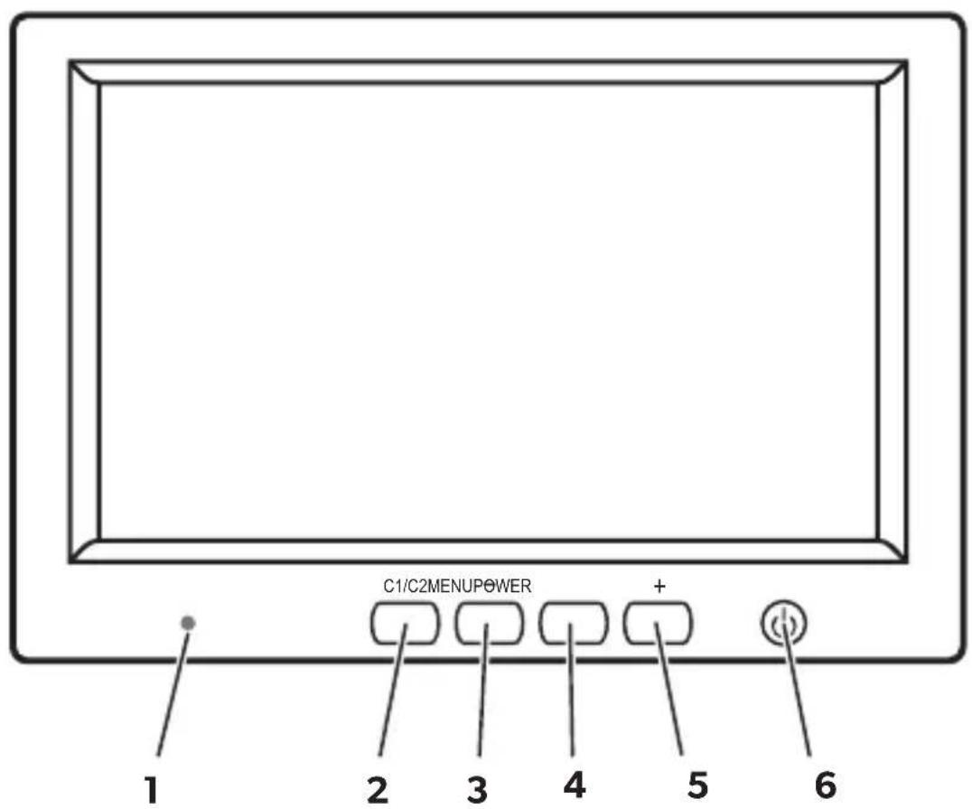
5.2 Operating elements
The following control elements are located on the monitor:
| No. in fig. 14, Designation Description page 8 | |
| 1 | L i |
| 2 C1/C2 Selects the camera or swaps menu page 1 and 2. | |
| 3 – Reduces the volume or other selected parameters (brightness, contrast, colour tint). | |
| 4 MENU Switches to setup mode (see chapter “Using the LCD-monitor” on page 21). | |
| 5 + Increases the volume or other selected parameters (brightness, contrast, colour tint). | |
| 6 | Switches the monitor on and off. |
6 General information on the electrical connections
6.1 Laying cables

NOTICE!
Cables and connections which are not properly installed will cause malfunctions or damage to components. Correct installation of cables and connections ensures lasting and trouble-free operation of the retrofitted components.
Please observe the following instructions:
- As far as possible, use original openings or alternative openings for the connecting cable duct, e.g. the paneling edges, ventilation grilles or blank panels. If no openings are available, you must drill holes for the cables. Check beforehand that there is sufficient space on the other side for the drill head to come out.
- Wherever possible lay cables inside the vehicle, as they are better protected there than outside the vehicle.
If you do need to lay a cable outside the vehicle, ensure that it is well secured (use additional cable ties, insulating tape, etc.).
- To prevent damage to the cables, when laying them, ensure that they are far enough away from hot or moving vehicle components (exhaust pipes, drive shafts, light systems, fans, heater etc.).
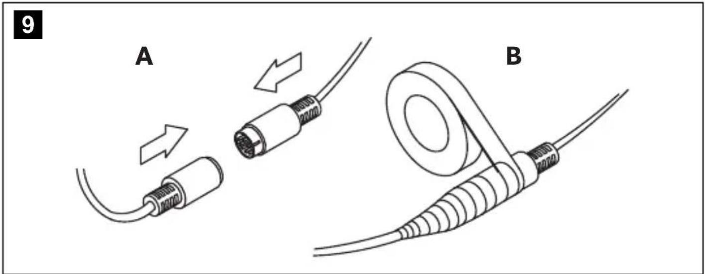
- Wrap insulating tape around the plug connections of the connecting cables and every connection on a cable (including inside the vehicle) to protect them from exposure to water (fig. 9, page 6). The most suitable tape for this purpose is self-vulcanising tape, for example from 3M.
- When laying electric connections (fig. 3, page 4), ensure that
– They are not kinked or twisted
– They do not rub on edges
– They are not laid in sharp edged ducts without protection
- Attach the cables securely in the vehicles to prevent tripping hazards. Use cable binders, insulating tape or glue the cables in place.
- Protect every through-hole made in the bodywork against water penetration, e. g. by using a cable with a sealant and by spraying the cable and the the cable sleeve with sealant.

NOTE
Do not start sealing the through-holes until you have completed all installation work on the camera, and the required cable lengths have been laid.
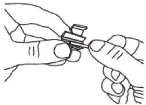
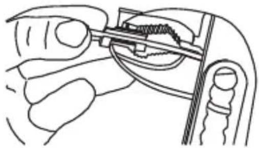
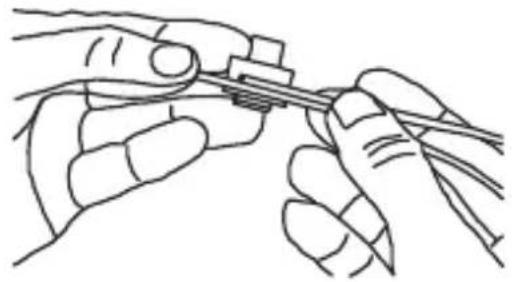
6.2 Using branch connectors (fig. 6, page 5)
To prevent loose connections in the branch connectors, it is important to ensure that the cable cross sections fit into the branch connectors.
To use the branch connectors, proceed as follows:
▶ Insert the cable to be tapped in the front groove of the cable connector (A).
▶ Insert the end of the new cable up to approx. 3/4 of the way into the rear groove (B).
▶ Use a pair of combination pliers to close the connector by pressing the metal pin in. This creates an electrical connection (C).
▶Press down the safety cap until it snaps into place.
▶ Check that the connection is secure by lightly tugging the cable (D).
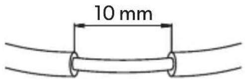
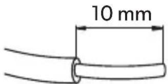
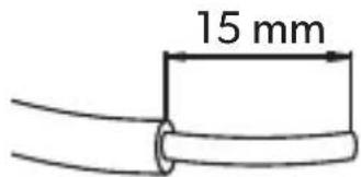
6.3 Creating clean soldering joints
Proceed as follows to solder a cable to the original cables (fig. 7, page 5):
▶ Strip approx. 10 mm of insulation from the end of the original cable (A).
▶ Strip approx. 15 mm of insulation from the end of the cable to be connected (B).
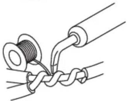
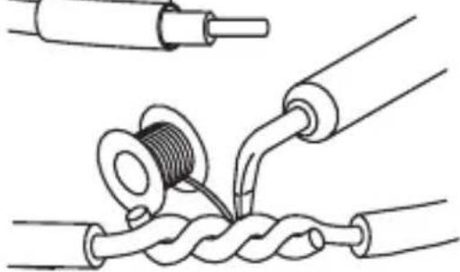
▶ Wind the cable to be connected around the original cable and solder the two cables together (C).
▶ Insulate the two cables with insulating tape (D).
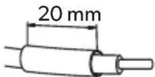
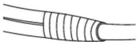
Proceed as follows to solder two cables together (fig. 8, page 5):
▶Strip the two cables (A).
▶ Place a shrink sleeve with a length of approx. 20 mm over the cable (B).
▶ Twist the cables together and solder them (C).
▶ Place a shrink sleeve over the soldered point and heat it briefly (D).
7 Mounting the monitor
7.1 Tools required (fig. 1, page 3)
For installation and assembly you will need the following tools:
- Measuring ruler (4)
- Centre punch (5)
- Hammer (6)
- Drill bit set (7)
- Drill (8)
- Screwdriver (9)
To make and test the electrical connection, the following tools are required:
• Diode test lamp (1) or voltmeter (2)
• Insulating tape (10)
- Heat shrinking sleeve
- Hot air blower (11)
- Crimping tool (12)
• Soldering iron (optional) (13)
- Solder (optional) (14)
• Cable bushing sleeves (optional)
Depending on the individual installation requirements you may require bolts, nuts, washers, self-tapping screws and cable binders other than those including in the scope of delivery.
7.2 Installing the monitor

CAUTION! Risk of injury!
Select the location of the monitor so that it cannot injure the passengers in the vehicle under any circumstances (e.g. sudden braking, road traffic accidents).
Observe the following installation instructions:
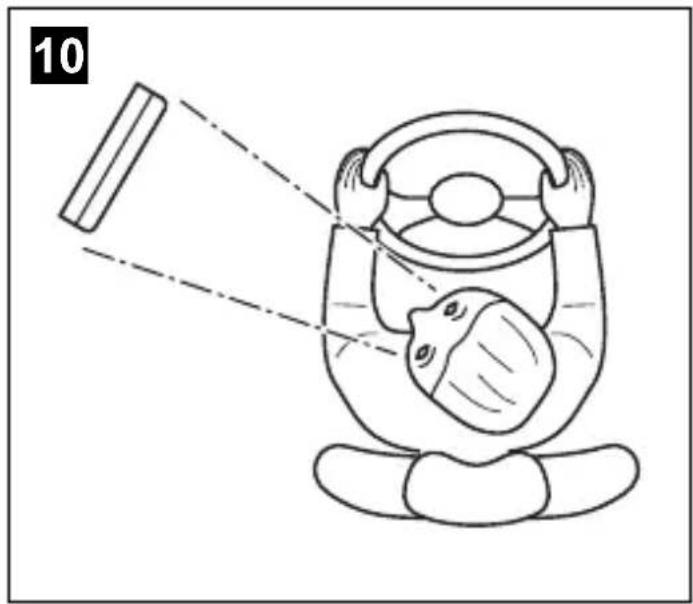
- Select an installation location that provides an unobstructed view of the monitor (fig. 10, page 6 and fig. 11, page 6).
- Never install the monitor in area where your head could impact it or in the air bag deployment path. This could cause injury if the airbag opens.
- The monitor must not impair your vision when driving (fig. 12, page 7).
- The installation location should be flat.
- Check that there is sufficient space underneath the installation location to attach the washers and nuts.
- Check beforehand that there is sufficient space on the other side for the drill head to come out.
- Bear in mind the weight of the monitor. Provide reinforcement if necessary (larger washers or plates).
- Ensure that you can lay the connection cable set to the monitor.
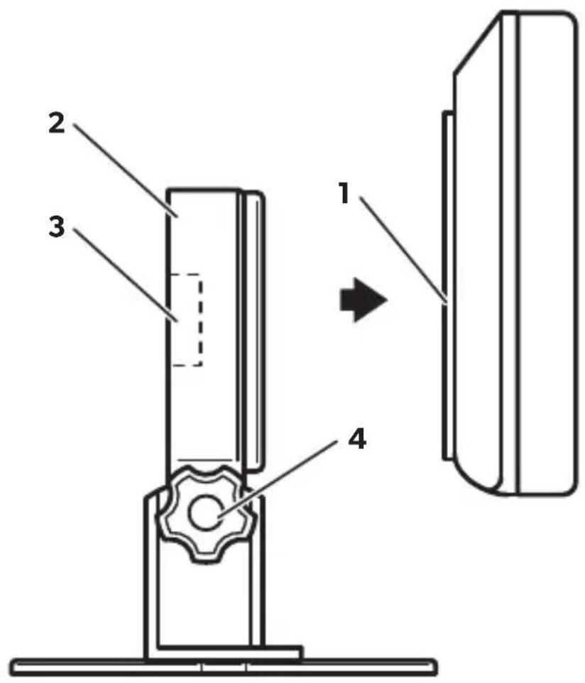
To perform the installation, proceed as follows (fig. 15, page 9):
▶ Slide the monitor (1) onto the mounting plate of the monitor bracket (2) and secure it on the monitor bracket with the knurled screw (3).
▶Position the monitor and the attached monitor bracket for testing.
▶ Mark the outlines of the corners of the monitor bracket (2) on the dashboard.
▶Unscrew the monitor from the monitor holder.
▶ Hold the monitor bracket within the outlines marked beforehand and mark four different drilling points.
▶ Drill ∅ 2 mm holes at the points you have just marked.
▶ Screw on the monitor bracket with the 4 x 20 mm self-tapping screws.
▶ Slide the monitor (1) onto the mounting plate of the monitor bracket (2) and secure it on the monitor bracket with the knurled screw (3).

NOTE
You can now adjust the angle of inclination. To do this, loosen the knurled screw (4) and tilt the monitor to the desired position. Tighten the knurled screw (4).
7.3 Laying the system cable from the camera to the monitor

NOTE
Lay the camera cable so that should you need to remove the camera, you can access the plug connection between the camera and the extension cable easily. This greatly facilitates the disassembly.
▶Lay the system cable for the camera inside the vehicle.
▶Lay the system cable for the camera to the monitor.
▶Connect the monitor connection cable to the system cable.
▶ Insulate the plug connection with the insulating tape supplied. Overlap every layer of the insulating tape by one half of its width.
▶ Attach the cables securely in the vehicles to prevent tripping hazards. This can be performed by using cable binders, insulating tape or gluing in place with adhesives.

NOTE
Only start sealing through-holes when you have completed all installation work on the camera and have laid the required cable lengths.
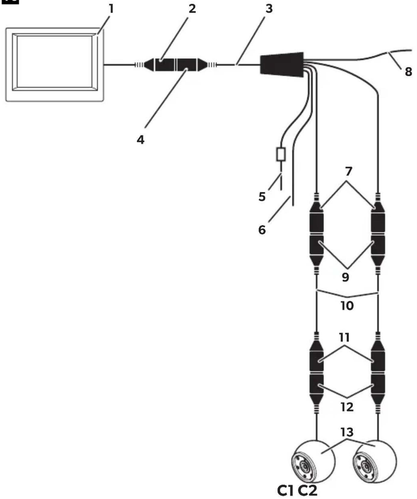
7.4 Connecting the monitor to an electricity supply (fig. 16, page 10)
The circuit diagram for the monitor can be found in fig. 16, page 10.
No. Description
| 1 | M | o | n | i | t | o | r | |||||||
| 2 13-pin DIN plug | ||||||||||||||
| 3 | C | o | n | n | e | c | t | i | o | n | c | a | b | l |
| 4 | l | 3 | - | p | i | n | D | l | N | s | o | c | k | e |
| 5 12 V positive cable (red): Connection to the positive pole of the voltage source | ||||||||||||||
| 6 Earth cable (black): Connection to the negative pole of the voltage source | ||||||||||||||
| 7 | 6 | - | p | i | n | D | l | N | s | o | c | k | e | t |
| 8 Cable (green): Control input for the connection to the reversing lights | ||||||||||||||
| 9 | 6 | - | p | i | n | m | i | n | i | D | l | N | p | l |
| 10 System cable | ||||||||||||||
| 11 6-pin mini DIN socket | ||||||||||||||
| 12 6-pin mini DIN plug | ||||||||||||||
| 13 Camera | ||||||||||||||
Observe the following instructions when laying the connection cable:
- Feed the connection cable through existing ducts or other openings where possible e. g. ventilation grilles. If no appropriate ducts or openings are available you will need to drill a hole of ∅ 18 mm. Check beforehand that there is sufficient space on the other side for the drill head to come out (fig. 2, page 4).
- Please observe the notes from the chapter "General information on the electrical connections" on page 16.
▶Lay the monitor cable on the dashboard.
▶ Insert the plug of the monitor cable (2) in the socket (4) of the connection cable (3).

NOTICE!
Make sure the polarity is correct when connecting to a voltage source.
Connect the red and black cables of the connection cables to a suitable voltage source:
- Connect the red cable (5) to terminal 15 (ignition).
- Connect the black cable (6) to terminal 31 (earth).
If necessary, connect the mini DIN socket (7) of the connection cable to the mini DIN plug (9) of the system cable (10).
Connect the mini DIN socket (11) of the system cable (10) of to the mini DIN plug (12) of the camera cable.
▶ Connect the green cable (8) to the positive cable of the reversing light.

NOTE
If a voltage is present on the green cable, the monitor is switched on automatically and the camera is activated.
8 Using the LCD-monitor
8.1 Switching on the monitor (fig. 14, page 8)

NOTE
The monitor is switched on automatically, if you shift into reverse gear. The image is transmitted by the camera.
▶ If the monitor is switched off, press the "Power" main switch (6), to switch the monitor on.
√The picture appears.
√The brightness of the display is automatically adapted to the ambient light.
8.2 Switching off the monitor (fig. 14, page 8)
▶ Press the main switch "Power" (6), to switch off the monitor.
√The picture disappears.
8.3 Setting the volume (fig. 14, page 8)
You can set the volume to amplify or mute the the noises transmitted by the camera.
▶ Press the “-” button (3) to reduce the volume.
▶ Press the “+” button (5) to increase the volume.
8.4 Setting the monitor (fig. 14, page 8)
To set the monitor to suit your requirements, proceed as follows:
▶ Press the "MENU" button (3) to call up the required parameter.
√The parameters to be set appear in the following order:
Page 1:
-Brightness: 0 - 100
- Contrast: 0 - 100
- Colour: 0 - 100
– Language: "English" or "German"
Page 2:
- Reset ("Default"): Default setting for all parameters
- Camera 1: "Normal" or "Mirrored"
- Camera 2: "Normal" or "Mirrored"
▶ Press the “−” button (4) or “+” button (5) to set the parameter of your choice.
▶ Press the “−” button (4) to reduce the value of the selected parameter.
▶ Press the "+" button (5) to increase the value of the selected parameter.
8.5 Setting the video source (fig. 14, page 8)

NOTE
If you have connected the green cable to the reversing light and voltage is present, reversing camera V1 is activated automatically.
If you wish to switch to a different video source (from camera 1 to camera 2), press the "C1/C2" button (2).
√ The monitor switches from camera 1 to camera 2 or vice-versa.
9 Cleaning and maintaining the LCD monitor

NOTICE!
- Do not use sharp or hard objects or cleaning agents for cleaning as these may damage the product.
- Remove the cable before cleaning the monitor to prevent short circuiting.
▶Occasionally clean the product with a damp cloth.
10 Guarantee
The statutory warranty period applies. If the product is defective, please contact the manufacturer's branch in your country (see the back of the instruction manual for the addresses) or your retailer.
For repair and guarantee processing, please include the following documents when you send in the device:
• A copy of the receipt with purchasing date
- A reason for the claim or description of the fault
11 Disposal
Place the packaging material in the appropriate recycling waste bins wherever possible.

If you wish to finally dispose of the product, ask your local recycling centre or specialist dealer for details about how to do this in accordance with the applicable disposal regulations.
12 Technical data
| M7LS | |
| Reference no.: 9600000204 | |
| Type: Colour TFT LCD | |
| Display size: 7" (17.8 cm) | |
| Brightness: Approx. 300 cd/m2 | |
| Display resolution, H x V: 337000 pixels | |
| Operating voltage: 11 – 16 V--- | |
| Power: Max. 8 W | |
| Operating temperature: -20 °C to +65 °C | |
| Storage temperature: -25 °C to +80 °C | |
| Relative humidity: | Max. 85 % |
| Vibration resistance: | 5 g |
| Dimensions (W x H x D): | 170 x 125 x 25 mm |
| Weight: | 400 g |
| Approval: |  |
5 Description technique
Dometic Australia Pty. Ltd.
1 John Duncan Court
Varsity Lakes QLD 4227
1800 212121
+61755076001
Mail: sales@dometic-waeco.com.au
AUSTRIA
Dometic Austria GmbH
Neudorferstraße 108
A-2353 Guntramsdorf
+43 2236 908070
+43 2236 90807060
Mail: info@dometic.at
BENELUX
Dometic Branch Office Belgium
Zincstraat 3
B-1500 Halle
+32 2 3598040
+32 2 3598050
Mail: info@dometic.be
BRAZIL
Dometic DO Brasil LTDA
Avenida Paulista 1754, conj. 111
SP 01310-920 Sao Paulo
+55 11 3251 3352
+551132513362
Dometic Group Asia Pacific
Suites 2207-11 · 22/F · Tower 1
The Gateway · 25 Canton Road,
Tsim Sha Tsui · Kowloon
+852 2 4611386
+852 2 4665553
Mail: info@waeco.com.hk
HUNGARY
Dometic Zrt. Sales Office
Kerékgyártó u. 5.
H-1147 Budapest
+3614684400
+3614684401
Dometic Italy S.r.l.
Via Virgilio, 3
I-47122 Forlì (FC)
+39 0543 754901
+390543754983
Mail: vendite@dometic.it
JAPAN
Dometic KK
Maekawa-Shibaura, Bldg. 2
2-13-9 Shibaura Minato-ku
Tokyo 108-0023
+81 3 5445 3333
昌 +81 3 5445 3339
Mail: info@dometic.jp
MEXICO
Circuito Médicos No. 6 Local 1
Colonia Ciudad Satélite
CP 53100 Naucalpan de Juárez
Estado de México
+52 55 5374 4108
+52 55 5393 4683
Mail: info@dometic.com.mx
NETHERLANDS
Dometic Benelux B.V.
Ecustraat 3
NL-4879 NP Etten-Leur
+31 76 5029000
+31 76 5029019
Mail: info@dometic.nl
NEW ZEALAND
Dometic New Zealand Ltd.
Unite E, The Gate
373 Neilson Street
Penrose 1, Auckland
+6496221490
+6496221573
Mail: customerservices@dometic.co.nz
NORWAY
Dometic Norway AS
∅sterøyveien 46
N-3232 Sandefjord
+47 33428450
+47 33428459
Mail: firmapost@dometic.no
POLAND
Dometic Poland Sp. z o.o.
Ul. Puławska 435A
PL-02-801 Warszawa
+48 22 414 3200
+48 22 414 3201
Mail: info@dometic.pl
PORTUGAL
Dometic Spain, S.L.
Komsomolskaya square 6-1
RU-107140 Moscow
+7 495 780 79 39
+7 495 916 56 53
Mail: info@dometic.ru
SINGAPORE
Dometic Pte Ltd
18 Boon Lay Way 06–140 Trade Hub 21
Singapore 609966
+65 6795 3177
+65 6862 6620
Mail: dometic@dometic.com.sg
SLOVAKIA
Dometic Slovakia s.r.o. Sales Office Bratislava
Nádražná 34/A
900 28 Ivánka pri Dunaji
+421 2 45 529 680
Mail: bratislava@dometic.com
SOUTH AFRICA
Dometic (Pty) Ltd.
Regional Office
South Africa & Sub-Saharan Africa
2 Avalon Road
West Lake View Ext 11
Modderfontein 1645
Johannesburg
+27114504978
+27114504976
Mail: info@dometic.co.za
SPAIN
Dometic Spain S.L.
Avda. Sierra del Guadarrama, 16
E-28691 Villanueva de la Cañada
Madrid
+34 902 111 042
+34 900 100 245
Mail: info@dometic.es
SWEDEN
Dometic Scandinavia AB
Gustaf Melins gata 7
Dometic Switzerland AG
Riedackerstrasse 7a
CH-8153 Rümlang
+41 44 8187171
+41 44 8187191
Mail: info@dometic.ch
UNITED ARAB EMIRATES
Dometic Middle East FZCO
P. O. Box 17860
S-D 6, Jebel Ali Freezone
Dubai
+97148833858
+97148833868
Mail: info@dometic.ae
UNITED KINGDOM
Dometic UK Ltd.
Dometic House, The Brewery
Blandford St. Mary
Dorset DT11 9LS
+44 344 626 0133
+44 344 626 0143
Mail: customerservices@dometic.co.uk
USA
Dometic RV Division
1120 North Main Street
Elkhart, IN 46515
+1 574-264-2131


