UF2415B - Pump Whale - Free user manual and instructions
Find the device manual for free UF2415B Whale in PDF.



User questions about UF2415B Whale
0 question about this device. Answer the ones you know or ask your own.
Ask a new question about this device
Download the instructions for your Pump in PDF format for free! Find your manual UF2415B - Whale and take your electronic device back in hand. On this page are published all the documents necessary for the use of your device. UF2415B by Whale.
USER MANUAL UF2415B Whale
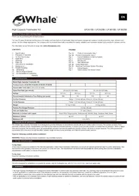
INSTALLATION & USER INSTRUCTIONS
Thank you for purchasing this Whale® product.
For over 70 years Whale has led the way in the design and manufacture of freshwater, bilge and waste management systems including plumbing, taps, showers and pumps, for low voltage applications. The company and its products have built a reputation for quality, reliability and innovation backed up by excellent customer service.
For information on our full product range visit: www.whalepumps.com
CONTENTS
| 1. | Specifi cation | Fig. 1A | Product Components View 1 |
| 2. | Principles of Operation | Fig. 1B | Product Components View 2 |
| 3. | To The Fitter & User | Fig. 2 | Typical Installation in Marine System |
| 4. | Application | Fig. 3 | Overall Dimensions |
| 5. | Warnings | Fig. 4 | Securing Kit |
| 6. | Parts List | Fig. 5A | Inlet Attachment |
| 7. | Instructions for Installation | Fig. 5B | Outlet Attachment |
| 8. | Maintenance | Fig. 5C | Attaching Freshwater System Plumbing |
| 9. | Trouble Shooting | Fig. 6 | Wiring Diagram |
| 10. | Winterising | Fig. 7 | Valve Location For Annual Check |
| 11. | Service Support Details | ||
| 12. | EU Declaration of Conformity | ||
| 13. | Warranty |
- SPECIFICATION
| Model High Capacity Freshwater Kit | ||||
| Product Codes UF2415B UF2425B UF3615B UF3625B | ||||
| Accumulator Tank size 2 Ltrs (0.53 US Gals) | ||||
| Open Flow Rate (per minute) | 24 Ltrs (6.3 US Gals) | 32 Ltrs (8.4 US Gals) | ||
| Voltage | 12 V d.c. | 24 V d.c. | 12 V d.c. | 24 V d.c. |
| Recommended Automotive Fuse Rating (per pump) | 10A | 5A | 12A | 8A |
| Cut Out Pressure | Pump 1: 3.0 bar (45 psi); Pump 2: 2.0 bar (30 psi) | |||
| Cut In Pressure | Pump 1: 2.0 bar (30 psi); Pump 2: 1.4 bar (20 psi) | |||
| Weight | 8.7 kg (19 lbs) | 9.8 kg (22 lbs) | ||
| Factory Pre-Charge Pressure | 2.2 bar (32 psi) | |||
| Inlet and Outlet Size | 34 " barb (19mm) | |||
| Materials in Contact with Liquid | Glass Filled Polypropylene, Santoprene®, Nitrile®, Butyl, Stainless Steel, Brass | |||
| Maximum Outlets | up to 6 | up to 8 | ||
| Maximum Lift | 3 m (10 ft) | |||
2. PRINCIPLES OF OPERATION
The Whale High Capacity Freshwater Kit is designed to provide freshwater in recreational vessels with up to 8 water outlets on board. The system consists of two automatic pressure pumps, independently controlled by two external pressure switches. A primary pump provides smooth consistent flow on activation. When a higher flow rate is required, the secondary pump will automatically activate to provide the additional capacity, and turn off when no longer required. The 2 litre pressurised accumulator tank ensures a smooth transition between single and dual pump activation, and helps to prevent water hammer.
Read the following carefully before installation
WARNING: Please note that incorrect installation may invalidate warranty.
3. TO THE FITTER & USER
To the Fitter:
Check that the product is suitable for the intended application, follow these installation instructions and ensure all relevant personnel read the points listed below. Also ensure that these operating instructions are passed on to the end user. The manufacturer cannot be held responsible for claims arising from incorrect installation, unauthorised modification or misuse of the product.
To the User:
Read the following instructions carefully.
4. APPLICATION
This kit is designed for installation in recreational vessels, only for freshwater use, with 12 V d.c. or 24 V d.c. electrical supply only.
5. WARNINGS
- The High Capacity Freshwater Kit is designed to deliver freshwater in leisure boats and personal watercraft. Your warranty may be invalidated if the product is used in other applications or outside the remit of the standards quoted on the packaging and product literature. If used for a different application, it is the user's responsibility to ensure the unit is suitable for the intended use and the materials are fully compatible with the liquids to be used.
-
With all applications, it is important that a system of safe working practice is applied to installation, use and maintenance. Ensure the electric supply is turned off and water system is drained before installation.
-
WARNING: Fire hazard. Wiring must comply with the applicable electrical standards and include a properly rated fuse or circuit breaker. Improper wiring can cause a fire resulting in injury or death. Switch off the power while making connections.
• Suggested wiring information is for guidance only. For full information, please refer to relevant ISO standards and regulations for marine applications. - Do not screw directly to the hull – MUST be mounted on a bulkhead or an additional board.
- A Whale® strainer is fitted on the inlet of each pump to prevent dirt/debris entering the pump. They must not be removed.
Contact Whale Support Tel: +44 (0)28 9127 0531 or email info@whalepumps.com for specifi c advice on your installation.
- PARTS
| QTY: 1 Pre-assembled Frame |
| QTY: 2 Freshwater Pressure Pump |
| QTY: 2 Whale® Strainer |
| QTY: 1 2 ltr Accumulator Tank |
| QTY: 2 External Pressure Switch |
| QTY: 1 Pre-assembled Plumbing |
text_image
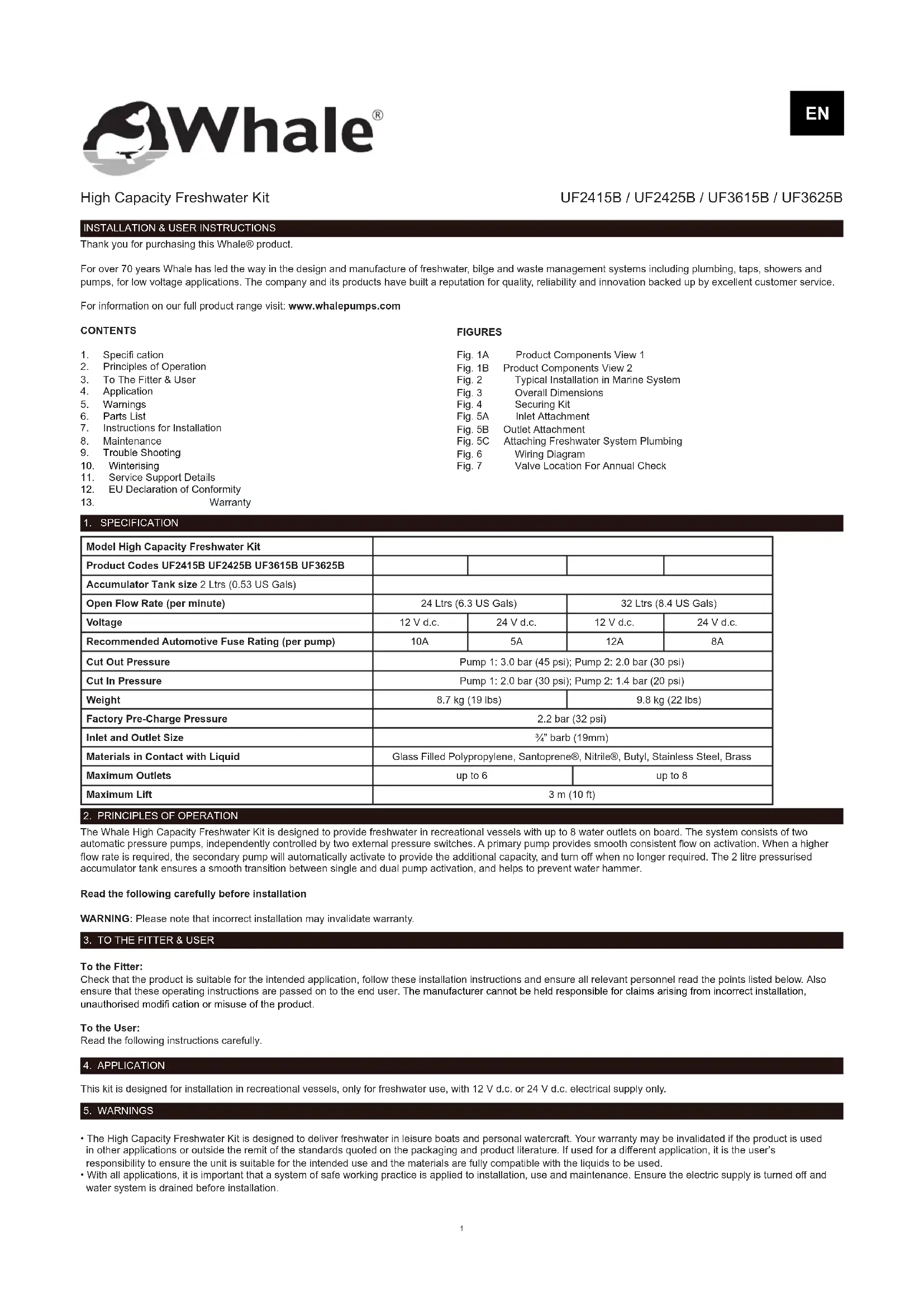
Inlet Strainers Primary pump electrical connections Secondary pump electrical connections 2 Ltr Accumulator Tank 3/4" (19mm) bar 3/4" (19mm) reinforced hoseFigure 1a Product Components View 1
text_image
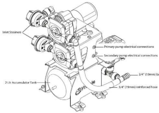
Primary pump External pressure switch, controlling secondary pump Secondary pump 3/4" (19mm) barb inlet outlet External pressure switch, controlling primary pump SwhaleFigure 1b Product Components View 2
7. INSTRUCTIONS FOR INSTALLATION
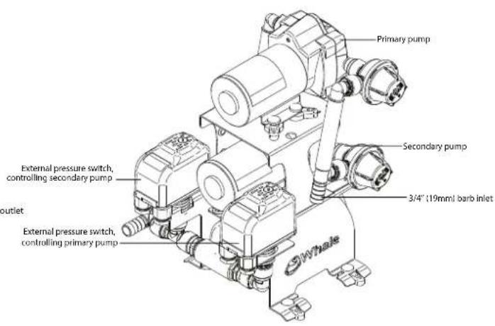
The High Capacity Freshwater Kit is designed for freshwater use in recreational vessels, typical installation is shown in Figure 2.
flowchart
graph TD
    A["Twist Deck Shower"] --> B["Quick Connect Elbow"]
    B --> C["Water Tank"]
    C --> D["19mm (3/4") Pipework - Inlet and Outlet"]
    D --> E["Stern Shut off Valve"]
    E --> F["Thermostatic Mixer"]
    F --> G["Expansion Vessel"]
    G --> H["Water Heater"]
    H --> I["Non-return Valve"]
    I --> J["Elegance Combo Mixer"]
    J --> K["Elite Faucet"]
    K --> L["Swan Neck Galley Faucet"]
    L --> M["Elegance Combo Mixer"]
Figure 2 Typical Installation in Marine System (illustration for guidance purposes only)
Overall dimensions of the High Capacity Freshwater Kit are shown in Figure 3. The High Capacity Freshwater Kit uses 34'' (19mm) barb connections on the inlet and outlet (Figure 5a, 5b and 5c). The outlet should be connected into the freshwater system at a central location.
Mounting Instructions
Step 1 Locate in a dry position with adequate ventilation and no more than 3m (9ft) above the water tank. In normal use, ensure the kit cannot be submerged in water. Step 2 Ensure the kit is mounted free of obstacles and is accessible for maintenance.
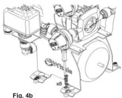
Step 3 Use stainless steel screws and washers to secure the kit to a solid surface. Four screws and washers can be used through the centre of the feet (see Fig. 4a), or 8 screws and washers as shown in Fig 4b.
DO NOT screw directly to the hull – MUST be mounted to a bulkhead or additional board.
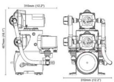
text_image
310mm (12.2") 407mm (18.1") 310mm (12.2)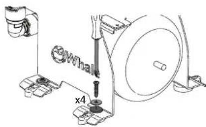
text_image
Whalk x4Fig. 4a
natural_image
Technical line drawing of a mechanical assembly with no visible text or symbolsFig. 4b
Figure 3 Overall Dimensions
Figure 4a and 4b Securing Kit
Plumbing
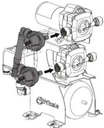
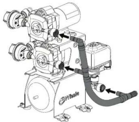
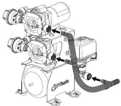
Attach the inlet pipework to the inlet side of the pumps (Figure 5a). Ensure a double click into the 2 Quick Connect fittings. Attach the outlet pipework to the outlet side of the pumps (Figure 5b). Ensure a double click into the 3 Quick Connect fittings.
natural_image
Technical line drawing of an air compressor unit with attached motors and valves (no text or symbols)Figure 5a Inlet Attachment
natural_image
Technical line drawing of a whale pump system with hoses and control unit (no text or symbols)Figure 5b Outlet Attachment
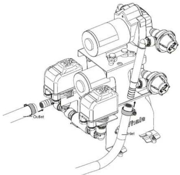
Secure pipework onto the 34 " (19mm) barb inlet and outlet, using appropriate hose clamps. Inlet and outlet are shown in Figure 5C. Do not overtighten.
text_image
Outlet Inlet HoleFigure 5c Attaching Freshwater System Plumbing
Electrical Wiring
The unit must be installed by a qualified electrician in accordance with applicable electrical standards.
WARNING: Fire Hazard. Wiring must comply with applicable electrical standards and include a properly sized fuse or circuit breaker. Improper wiring can cause a fire resulting in injury or death.
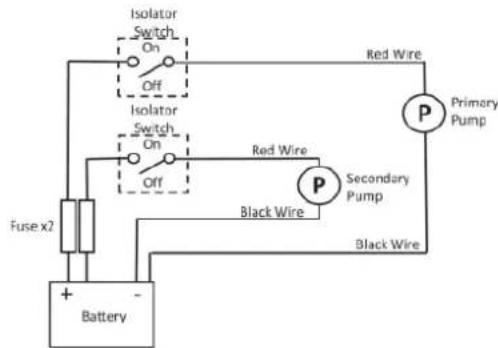
Switch off the power prior to making connections. Suggested wiring information shown in Figure 6 is given as a guide only. For full information, refer to the relevant ISO regulations for marine applications and wiring gauges, connectors and fuse protection.
text_image
Isolator Switch On Off Isolator Switch On Off Red Wire Primary Pump Fuse x2 Red Wire Secondary Pump Black Wire Black Wire + - BatteryFigure 6 Wiring Diagram
Instructions for Use
1) Ensure that the kit installation is tested thoroughly before use.
2) Once installed into the freshwater system, ensure the water tank is full and open all outlets.
3) Connect power to the kit and allow to run to remove air from the system.
4) Once air has been removed from the freshwater system, close all the outlets.
The secondary pump should turn off first (at 2.0 bar), followed by the primary pump (3.0 bar).
5) Check the priming of both pumps (both strainers should be filled with water).
6) Check the start and stop of both pumps. This should be automatic by opening and closing outlets.
7) The secondary pump will only activate with several outlets open.
8) Check for any leaks or loose connections.
8. MAINTENANCE
The High Capacity Freshwater Kit is designed to only require minimal maintenance.
WARNING: Ensure that the kit is disconnected from the electrics and system is fully drained prior to maintenance.
For optimal performance, ensure the pumps are clear of debris. Filter strainer meshes must be regularly removed and cleaned.
Annual Checks
- The vessel's plumbing and electrical systems must be checked at least annually for leaks and obstructions.
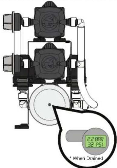
- Check accumulator tank pressure annually, as shown in Figure 7. Use hand or foot pump to increase pressure if required.
text_image
2.280R 32 PSI * When DrainedFigure 7 Valve Location For Annual Check
- TROUBLE SHOOTING
| Problem Possible Cause Potential Solution | ||
| Primary and/or secondary pump does not run | No power to pump Check power supply. Check leads and clean connections. | |
| Fuse has blown Replace fuse. | ||
| Pump is faulty Replace pump. | ||
| Pressure switch is faulty | Check operation and replace if faulty (AK1314 for Low Pressure Switch and AK1315 for High Pressure Switch) | |
| Pump(s) runs but no water appears | No water getting to pump / blockage in pipework | Check the water tank is not empty. Check strainers are not blocked. Check all connections from tank to inlet of the kit are secure – air leaks will prevent prime. |
| Pressure relief valve too low | Check water supply level and pressure relief settings are appropriate for the system. | |
| Water leaking at outlet side of pump | Check pipework/fi ttings for leaks and repair. Check system drain plugs are closed. | |
| Pump(s) runs but will not switch off | Water leaking at outlet side of pump | Check pipework/fi ttings for leaks and repair. Check system drain plugs are closed. |
| Insufficient water getting to pump Check water supply levels. | ||
| Problem Possible Cause Potential Solution | ||
| Pump cycles on and off periodically when all the taps are closed | Water leaking at outlet side of pump | Check pipework/fi ttings for leaks and repair. Check system drain plugs are closed. System pressure relief valve too low. |
| Noisy operation | Pumps drawing air See 'no water getting to pump' (above). | |
| Noise created by vibration | Check kit is secured to a solid surface. Check frame is not in contact with hard surfaces. Located away from interfering surfaces. Check pipework is securely supported. | |
| Low flow | Power supply to pumps | Check power supply to pumps uses the correct wire gauge in line with relevant standards, to give full voltage at pumps.Check battery is not discharged. |
| Pipework/connections crushed due to over tightened hose clips | Replace damaged connections. Ensure no kinks or tight bends in pipework. | |
| Pumps too far from water tank Pump is best situated beside water tank. | ||
| Water leaking at outlet side of pumps | Check pipework/fi ttings for leaks and repair. Check system drain plugs are closed. | |
| Pump strainer clogged | Remove clear lid, rinse and replace to main strainer body (retain strainer mesh on lid). | |
| One pump is not functioning | Check power supply and electrical connection to pump.Check pressure switch is functioning. Replace pump (AK2415: 12ltr, 12V d.c.; AK2425: 12ltr, 24V d.c.; AK3615: 18ltr, 12V d.c.; AK3625: 18ltr, 24V d.c.) or pressure switch (AK1314 for Low Pressure Switch and AK1315 for High Pressure Switch). | |
| Flow is not smooth | Accumulator tank pressure is low | Check pressure in tank using the valve and a pressure gauge. If required, infl ate to 2.2bar. |
10. WINTERIZING
If water is allowed to freeze in the system, serious damage to the pipework and pump may occur. Failures of this type will invalidate the warranty. To best avoid this damage, completely drain the water system.
- Drain the tank either using the pumps or a drain valve.
- Open all faucets (including drain valve) and allow the pumps to purge all water from the system.
- Remember to leave all faucets including showers open (excluding the Whale Twist® Deck Shower, which must remain closed) to avoid any damage.
11. SERVICE SUPPORT DETAILS
For installation or service advice please contact Whale® Customer Support:
Tel: +44 (0)28 9127 0531
Email: info@whalepumps.com
www.whalepumps.com
12. EU DECLARATION OF CONFORMITY
We hereby declare, under our sole responsibility, that the enclosed equipment complies with the provisions of the following EC Directives.
Electromagnetic Compatibility Directive 2014/30/EU on the approximation of the laws of the Member States relating to electromagnetic compatibility.
CE mark affi xed: April 2017
Basis on which conformity is declared - The above equipment complies with the protection requirements of the EMC Directive.
Standards applied
2013/53/EU Recreational Craft Directive
ISO 10133:2012 Extra-low voltage DC Installation
EN55014-1:2006 EMC Emissions
EN55014-2:1997+A2:2008 EMC Immunity
EN28846:1993 Ignition Protection
ABYC-H23 Installation of Potable Water
Richard Bovill
Engineering Director
13. WARRANTY
This Whale® product is covered by a 2 year warranty. Please see the enclosed document for details of our Statement of Limited Warranty.
©Copyright Whale 2019 - All rights reserved. Reproduction in whole or in part without permission is prohibited. WHALE®, is a registered trademark of Munster Simms Engineering Limited, Bangor, Northern Ireland trading as Whale. Whale's policy is one of continuous improvement and we reserve the right to change specifications without prior notice. Illustrations are for guidance purposes only. Neither the accuracy nor completeness of the information contained in this or any product literature is guaranteed by the Company and may be subject to change at its sole discretion.
Munster Simms Engineering Ltd.
2 Enterprise Road, Bangor, Co. Down, N. Ireland BT19 7TA
Tel: +44 (0)28 9127 0531 Email: info@whalepumps.com www.whalepumps.com
INSTALLATION ET INSTRUCTIONS D'UTILISATION
natural_image
Technical line drawing of a mechanical pump assembly with labeled components (no readable text or symbols)natural_image
Technical line drawing of a whale pump system with hoses and control components (no text or labels)Munster Simms Engineering Ltd.
2 Enterprise Road, Bangor, Co. Down, Irlande du Nord BT19 7TA
Tél.: +44 (0)28 9127 0531 E-mail: info@whalepumps.com www.whalepumps.com
natural_image
Technical line drawing of a mechanical pump assembly with no visible text or symbolsnatural_image
Technical line drawing of a whale pump system with hoses and control unit (no text or symbols)Munster Simms Engineering Ltd.
2 Enterprise Road, Bangor, Co. Down, Irlanda del Nord BT19 7TA
Telefono: +44 (0)28 9127 0531 E-mail: info@whalepumps.com www.whalepumps.com
natural_image
Technical line drawing of a mechanical pump assembly with labeled components (no readable text or symbols)natural_image
Technical line drawing of a whale pump system with hoses and control unit (no text or symbols)Munster Simms Engineering Ltd
2 Enterprise Road, Bangor, Co. Down, Irlanda del Nord BT19 7TA
Tel: +44 (0)28 9127 0531 Email: info@whalepumps.com www.whalepumps.com
natural_image
Technical line drawing of a mechanical pump assembly with no visible text or symbolsFigura 5a Acoplamiento de entrada
natural_image
Technical line drawing of a whale pump system with hoses and control unit (no text or symbols)Figura 5b Acoplamiento de salida
Munster Simms Engineering Ltd.
2 Enterprise Road, Bangor, Co. Down, Irlanda del Norte BT19 7TA
Tel.: +44 (0)28 9127 0531 Correo electrónico: info@whalepumps.com www.whalepumps.com
INSTALLATIONS- & ANVÄNDARANVISNINGAR
natural_image
Technical line drawing of an air compressor assembly with no visible text or symbolsnatural_image
Technical line drawing of a mechanical pump assembly with hoses and components (no text or symbols)Munster Simms Engineering Ltd.
2 Enterprise Road, Bangor, Co. Down, N. Irland BT19 7TA
Tel: +44 (0)28 9127 0531 E-postadress: info@whalepumps.com www.whalepumps.com
ASENNUS- JA KÄYTTÖOHJEET
natural_image
Technical line drawing of a mechanical pump assembly with no visible text or symbolsnatural_image
Technical line drawing of a whale pump system with hoses and control components (no text or labels)text_image
USCITA male ENTRATA11. HUOLTOTUKITIEDOT
Munster Simms Engineering Ltd.
2 Enterprise Road, Bangor, Co. Down, Pohjois-Irlanti BT19 7TA
Puhelin: +44 (0)28 9127 0531 Sähköposti: info@whalepumps.com www.whalepumps.com