Smartbail - Pump Whale - Free user manual and instructions
Find the device manual for free Smartbail Whale in PDF.


User questions about Smartbail Whale
0 question about this device. Answer the ones you know or ask your own.
Ask a new question about this device
Download the instructions for your Pump in PDF format for free! Find your manual Smartbail - Whale and take your electronic device back in hand. On this page are published all the documents necessary for the use of your device. Smartbail by Whale.
USER MANUAL Smartbail Whale
natural_image
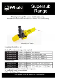
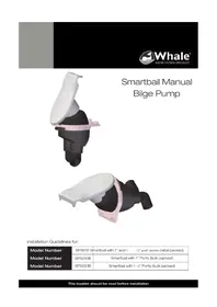
3D rendered mechanical component with white and black parts, no visible text or symbolsSmartbail Manual Bilge Pump
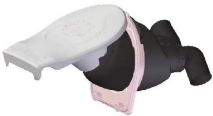
natural_image
3D rendered image of a person lying down with a white headboard and pink armrest (no text or symbols visible)Installation Guidelines for:
| Model Number | BP5012 S | smartbail with 1" and 1 1/2" port option (retail packed) |
| Model Number | BP5010B | Smartbail with 1" Ports (bulk packed) |
| Model Number | BP5021B | Smartbail with 1 1/2" Ports (bulk packed) |
Please ensure all relevant personnel read the points listed below before installation of the pump and this is passed on to the end user.
Application
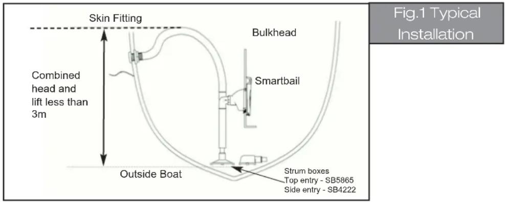
The Whale Smartbail bilge pump is designed to pump standing water when installed through the bulkhead (see fig.1 below). Output capacity depends on installation conditions and pumping rate. WARNING: Capacity may not be sufficient to cope with a rapid influx of water.
With all applications it is important that a system of safe working practice is applied to installation, use and maintenance.
If this pump is intended for use for any other purpose outside of the stated guidelines or with any other liquid, it is the user's responsibility to ensure that the pump is suitable for the intended use, and in particular, that the materials are fully compatible with the liquids to be used.
Before Installation
text_image
Skin Fitting Combined head and lift less than 3m Bulkhead Smartbail Outside Boat Strum boxes Top entry - SB5865 Side entry - SB4222 Fig.1 Typical Installation- Ensure that there is enough room behind the bulkhead for full depth of the pump when installed. This must include space for inlet and outlet hoses. (See Fig. 2 for maximum dimensions).
text_image
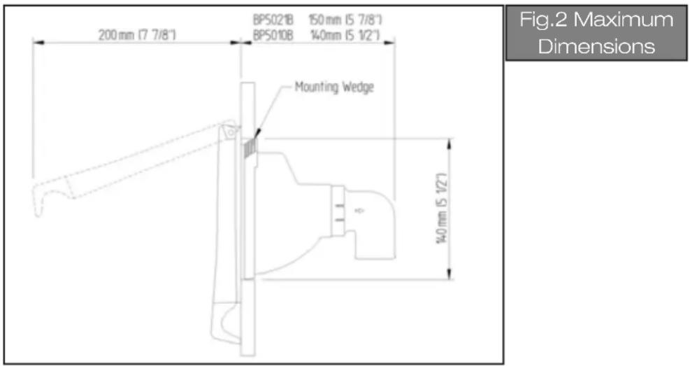
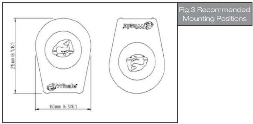
200 mm (7 7/8") BPS021B 150 mm (5 7/8") BPS010B 140 mm (5 1/2") Mounting Wedge 40 mm (5 1/2) Fig.2 Maximum Dimensions- Ensure that enough space is available when the pump is installed in order to operate it with the pump handle fully open. (See fig.3 for recommended mounting positions).
text_image
275 mm 16.7/6.7 160 mm 16.5/6.7 Whole SICUM Fig.3 Recommended Mounting PositionsMounting
- Select a suitable flat location on the bulkhead and cut out a circular hole diameter 140mm (5½").
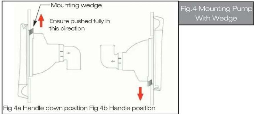
- Place pump through hole and push into position. Either pushing up or down depending on mounting orientation (see fig 4a and b).
text_image
Mounting wedge Ensure pushed fully in this direction Fig.4 Mounting Pump With Wedge Fig 4a Handle down position Fig 4b Handle position-
Ensure that the mounting wedge is fully engaged with the bulkhead.
-
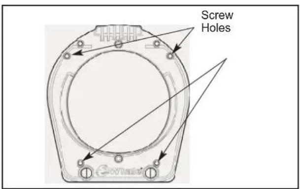
Open handle and mark the position of the 4 fixing screw holes on the bulkhead (see fig.5). Note - The pump must be installed using 4 screws.
text_image
Screw HolesFig.5 View Of Mounting Positions (Ommiting The Handle)
text_image
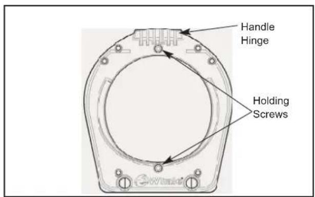
Handle Hinge Holding ScrewsFig.6
- Remove pump and drill 4 holes at these marked positions. See table below for recommended screw holes and sizes:
| Pilot Drill Hole Self-tapping Screw | |
| Diameter 3.5 mm Diameter | 5 mm |
- Place pump in position and attach to bulkhead using 4 self tapping screws.
Plumbing
- Attach inlet/outlet hoses to appropriate elbow at the rear of the pump with stainless steel worm drive clips.
Note:
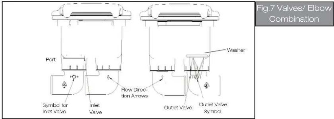
Both inlet and outlet elbows can be attached to either port. It is very important that the correct valve is installed with the correct port (see fig. 7). See icon on side of each port to confirm the correct valve has been installed with correct port (flat valve on inlet and tricuspid valve on outlet).
text_image
Port Symbol for Inlet Valve Inlet Valve Flow Direc- tion Arrows Washer Outlet Valve Outlet Valve Symbol Fig.7 Valves/ Elbow Combination| Symbol | Valve Flow Direction/ Elbow | |
| Tricuspid | Outlet Elbow | |
| Flap Inlet Elbow | ||
- It is recommended that the inlet and outlet hoses are restrained a minimum of 300mm (11 34 ) away from the pump to avoid undue stress on the inlet and outlet ports.
For installations where it is necessary to remove elbows before plumbing, the following additional steps are required:
-
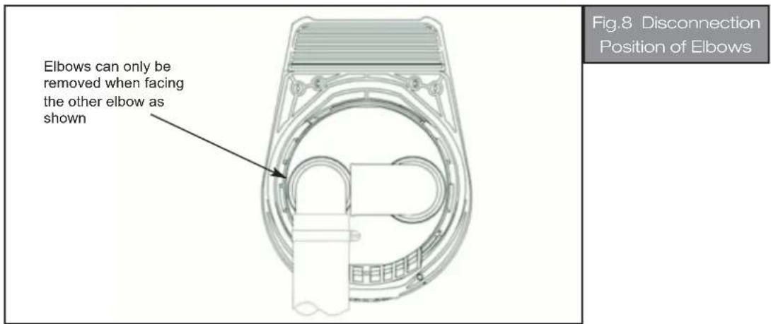
The elbows can be removed and hoses attached prior to installation by turning the elbows to a point where the outlet/inlet elbow directly faces the other elbow and then pulling out. See fig. 8 (below).
-
If the elbows have been removed, re-attach simply by pressing the elbow into its correct port until it "clicks" into place.
text_image
Elbows can only be removed when facing the other elbow as shown Fig.8 Disconnection Position of ElbowsTechnical Specifications
| Whale Smartbail | |
| Product Code | BP5010B, BP5021B |
| Weight | 0.6 kg |
| Hose Connections | BP5010B - 25 mm ports (1")BP5021B - 38 mm ports (1 1/2") |
| Materials | Glass-filled Polypropylene, Stainless Steel,Nitrile, Santoprene® |
| Materials In Contact With Fluid | Pump body: Glass-filled PolypropyleneInlet and outlet valves: NitrileDiaphragm: Santoprene® |
| Service Kit | AK5010 - Diaphragm, valves and seals |
Performance Data
| Maximum Head | 3m (9.8ft) | ||||
| Maximum Lift (self-priming) | 3m (9.8ft) | ||||
| Maximum Combined Head and Lift | 3m (9.8ft) | ||||
| Product Code | BP5010B BP5021B | ||||
| Port Size | 25 mm (1") 38 mm (1 | ^1/2 " | |||
| Lift Head | Flow Rate at 45 Strokes/min | Flow Rate at 60 Strokes/min | Flow Rate at 45 Strokes/min | Flow Rate at 60 Strokes/min | |
| 0 m (0 ft) 0 | m (0 ft) | 38.5 ltrs/min10.2 US gals/min | 51.3 ltrs/min13.6 US gals/min | 43.5 ltrs/min11.5 US gals/min | 58 ltrs/min15.3 US gals/min |
| 0 m (0 ft) 1 | m (3 ft) | 32.75 ltrs/min8.7 US gals/min | 43.6 ltrs/min11.5 US gals/min | 43.5 ltrs/min11.5 US gals/min | 58 ltrs/min15.3 US gals/min |
Performance data is based on factory test at specified lift and head and is typical of what may reasonably be achieved. Actual performance may vary depending on installation and operating conditions.
Standards Applied: ISO15083
Operation
- To operate the pump, open the cover by gripping the handle.
- The pump is then ready for instant operation.
- After use, push firmly to lock the handle in the closed position.
Maintenance
Regular inspection of the pump is recommended. Rubber components should be replaced if worn or every three years.
Service kit number - AK5010.
Replacing the Diaphragm:
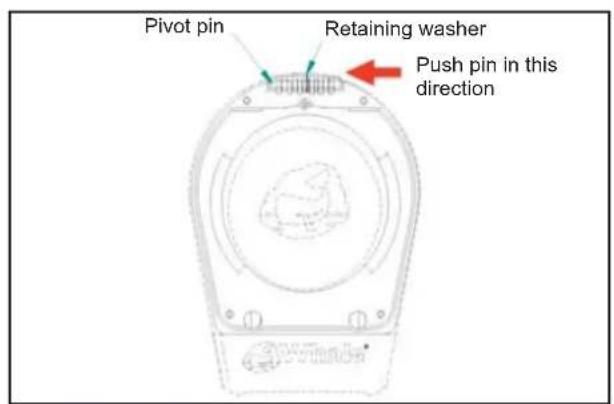
- Press out hinge pin in illustrated direction using appropriate force (then slide off handle). Care should be taken to keep the retaining washer in a safe place (see fig. 9).
- Remove pump from bulkhead by removing mounting screws and disconnecting mounting wedge (see fig 5).
text_image
Pivot pin Retaining washer Push pin in this directionFig.9
text_image
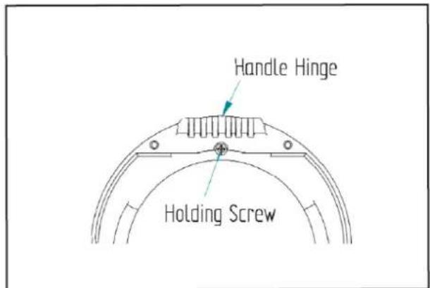
Handle Hinge Holding ScrewFig.10
-
Remove holding screws (see fig.10).
-
Rotate the front of the pump anti-clockwise until it reaches a stop (approx. 35 degrees) and lift off front part of the pump body.
-
The diaphragm can now be removed.
-
To install the new diaphragm ensure it is placed in the correct location (See fig.11). A small amount of lubricant e.g. vegetable oil applied to the edge of the diaphragm may ease installation.
-
Once replacement diaphragm is installed, re-attach the front of the pump and rotate clockwise until it reaches a stop (approx. 35 degrees).
-
Re-attach the handle by reconnecting the hinge, pressing the pin through the retaining washer (See fig. 9).
-
Re-mount the pump as per previous mounting instructions.

natural_image
Technical line drawing of a mechanical component with cross-sectional view (no text or symbols)Fig.11
Replacing Valves:
- Remove pump from bulkhead by unscrewing mounting screws and disconnecting mounting wedge.
- Disconnect hose from elbows.
- Remove elbows from ports (see Fig.8).
- It is very important that the elbows are re-installed with the correct valves inside the correct ports (see fig 7).
- Ensure the washer on the outlet valve is removed and placed on the replacement valve.
- To re-install the elbow after replacing the valve, simply press the elbows into the ports till they "click" into place.
Winterisation: To avoid damage as a result of freezing, drain all water in the pipework and pump chamber.
Warranty: This Whale® product is covered by a 3 year warranty - Please see enclosed document for details of our statement of limited warranty
Fig.2 Dimensions maximum
text_image
25 mm 16.7/16.7 Whole 16/mm 16.5/16.7 A Bnatural_image
Technical line drawing of a mechanical component with cross-sectional and top views (no text or symbols)Fig. 11
natural_image
Technical line drawing of a mechanical component with cross-sectional view (no text or symbols)Fig.11
text_image
25mm 8.7/16" Whole 10mm 6.5/16" A Btext_image
21mm 6.7/6.7 Whole 16mm 6.5/6.7 A B©Copyright Whale 2017 - All rights reserved. Reproduction in whole or in part without permission is prohibited. WHALE® is a registered trademark of Munster Simms Engineering Limited, Bangor, Northern Ireland trading as Whale. Whale's policy is one of continuous improvement and we reserve the right to change specifications without prior notice. Illustrations are for guidance purposes only.
Neither the accuracy nor completeness of the information contained in any Product brochure is guaranteed by the Company and may be subject to change at its sole discretion.
Please note that by contacting Whale Support you will be indicating your consent to receiving product updates, recall information, help guides and appropriate marketing messages from us via post, email or telephone unless you indicated an objection to receiving such messages.
Whale
2 Enterprise Road, Bangor, N. Ireland BT19 7TA
Tel: +44 (0)28 9127 0531
Email: info@whalepumps.com
www.whalepumps.com
Whale The Americas
Tel: +1 (616) 897-9241
Email: usasales@whalepumps.com
www.whalepumps.com
Ref: 180.24_v3_0117