Supersub Smart - Pump Whale - Free user manual and instructions
Find the device manual for free Supersub Smart Whale in PDF.



User questions about Supersub Smart Whale
0 question about this device. Answer the ones you know or ask your own.
Ask a new question about this device
Download the instructions for your Pump in PDF format for free! Find your manual Supersub Smart - Whale and take your electronic device back in hand. On this page are published all the documents necessary for the use of your device. Supersub Smart by Whale.
USER MANUAL Supersub Smart Whale
The original low profile narrow electric bilge pump.
Please Note: Pump operates with a 5 second on delay on automatic setting
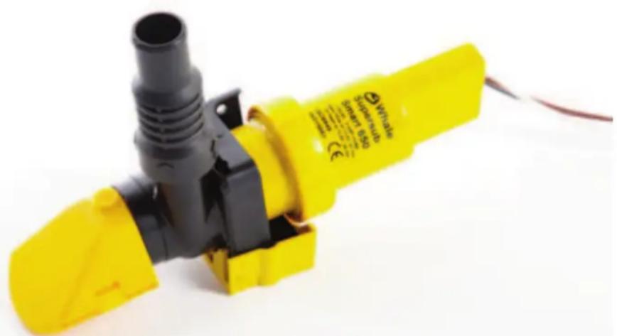
natural_image
Yellow and black plastic pump device with attached pipe fitting (no visible text or symbols)Model shown: SS5212
Installation Guidelines for:
Standard Pumps (separate bilge switch required)
| Model Number | SS5012 (B) Supersub 500 (12V d.c.) |
| Model Number | SS5022 (B) Supersub 650 (12V d.c.) with N.R.V. |
| Model Number | SS1012 (B) Supersub 1100 (12V d.c.) with N.R.V. |
| Model Number | SS1024 (B) Supersub 1100 (24V d.c.) with N.R.V. |
Automatic Pumps
| Model Number | SS5212 (B) | Supersub Smart 650 (12V d.c.) with N.R.V. |
| Model Number | SS1212 (B) | Supersub Smart 1100 (12V d.c.) with N.R.V. |
| Model Number | SS1224 (B) | Supersub Smart 1100 (24V d.c.) with N.R.V. |
Mounting wedge is supplied with automatic pumps only.
* B Suffix refers to bulk packed versions
Thank you for purchasing this Whale product.
For over 60 years Whale has led the way in the design and manufacture of freshwater, bilge and waste management systems including plumbing, taps, showers and pumps, for low voltage applications. The company and its products have built a reputation for quality, reliability and innovation backed up by excellent customer service. For information on our full product range visit: www.whalepumps.com
CONTENTS LIST OF IMAGES
| 1. Principles of Operation | 6. Instructions for use |
| 2. Application | 7. Trouble shooting |
| 3. Warning | 8. Winterization |
| 4. Optional Extras | 9. Service Support & Warranty |
| 5. Installation Instructions | 10. Declaration of conformity, standards, approvals |
Figure 1. Installation & Recommendations
| Figure 2. Fitting Instructions |
| Figure 3. Fitting Instructions - Into Existing Drill Holes |
| Figure 4. Typical Installations |
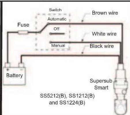
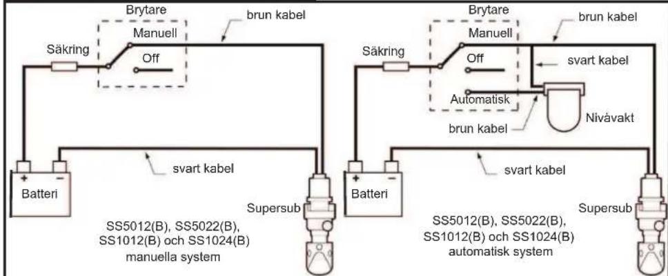
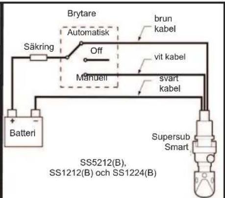
| Figure 5. Wiring Diagrams |
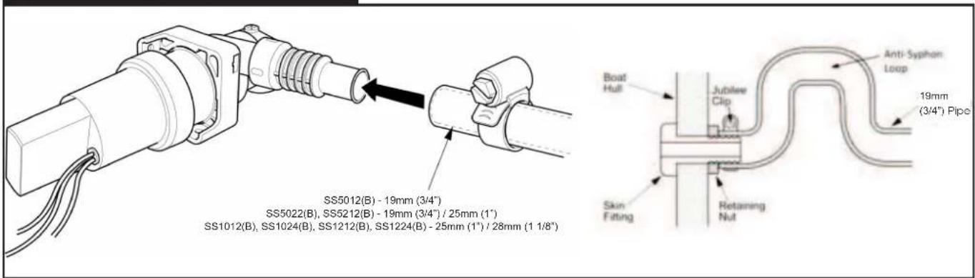
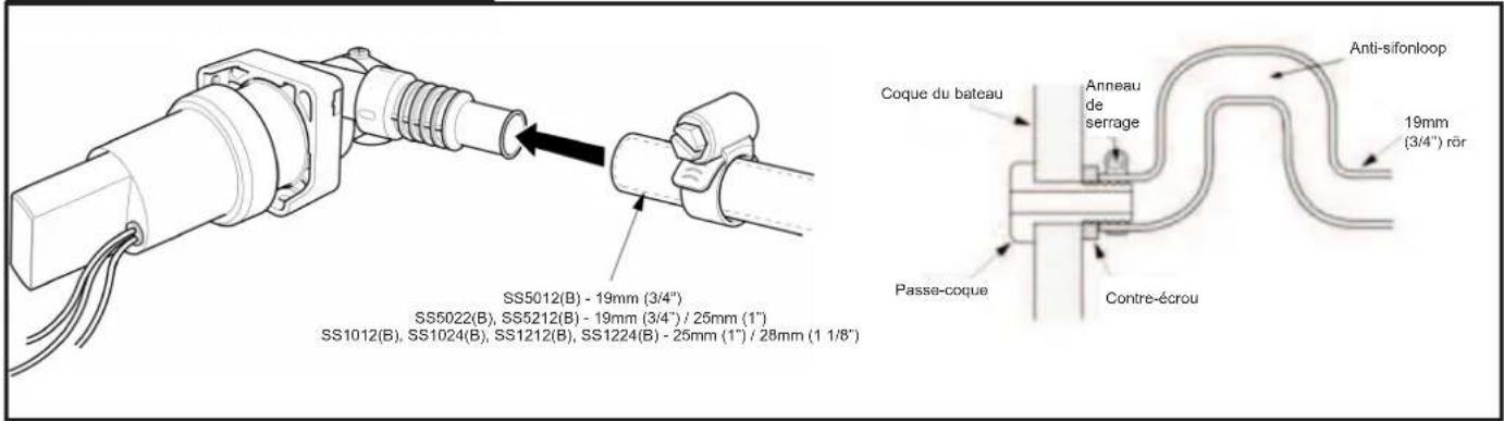
| Figure 6. Plumbing |
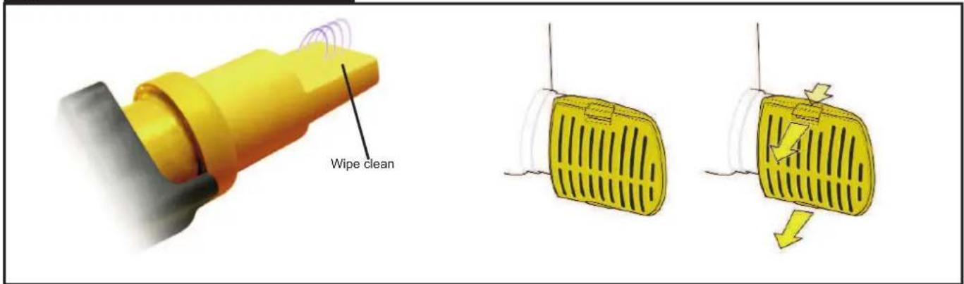
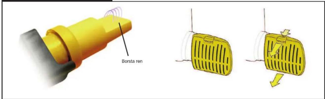
| Figure 7. Maintenance |
To the fitter
Read the following carefully before installation. Check that the product is suitable for the intended application, follow these installation instructions and ensure all relevant personnel read the points below. Also ensure that these operating instructions are passed on to the end user. WARNING: Please note that incorrect installation may invalidate warranty.
To the user
Read the following instructions carefully.
1. Principles of Operation
All Supersub models are uniquely designed, specifically for fast and efficient removal of bilge water from leisure craft. The Supersub range fits into narrow and low spaces that other bilge pumps cannot reach. SS5012, SS5022, SS1012 AND SS1024 ARE NOT AUTOMATIC PUMPS. (Please refer to Section 4 for the switches and optional extras that can be used with these products).
Supersub Smart 650 and 1100 are automatic. The pump will sense the presence of water and will switch on, then will turn off again when the water level has dropped. The switching is solid state hence there are no moving parts. The Supersub Smart models allow waves of water to pass over, without turning the pump on every time, as it has a built in time delay.
2. Application
- The Supersub and Supersub Smart range of products are designed to pump normal bilge water. Output capacity depends on installation and operating conditions. If this product is intended to be used for any other purpose or with any other liquid, it is the user's responsibility to ensure that the pump is suitable for the application and, in particular, that the materials are fully compatible with the liquids to be used.
- This product must only be used in the bilges of leisure craft. If this product is to be used as the sole and/or primary bilge pump, the Supersub 500/650/1100 and Supersub Smart 650/1100 pumps must only be used in boats up to 24m (78.8 ft).
- The bilge water must only be evacuated through a correctly installed skin fitting above the water line of the boat.
3. Warning
- With all applications, it is important that a system of safe working practice is applied to installation, use and maintenance. Ensure the electric supply is turned off and waste water system is drained before installation.
- The Supersub range is designed only for the removal of normal bilge water in leisure boats and personal watercraft (as explained in Section 2 - Application). Your warranty may be invalidated if the product is used in other applications or outside the remit of the standards quoted on the packaging and pump body.
- NOTE: Bilge pump capacities may not be sufficient to prevent flooding from rapid accumulation of water due to storms, rough weather and/or rapid leaks created by hull damage and or unsafe navigational conditions.
- The pumped water must be evacuated through a skin fitting above the water line (see typical installation diagrams). The Supersub and Supersub Smart range is not for use in systems evacuating water through a skin fitting or seacock below the water line. All pipework must contain a correctly installed anti-syphon valve / loop.
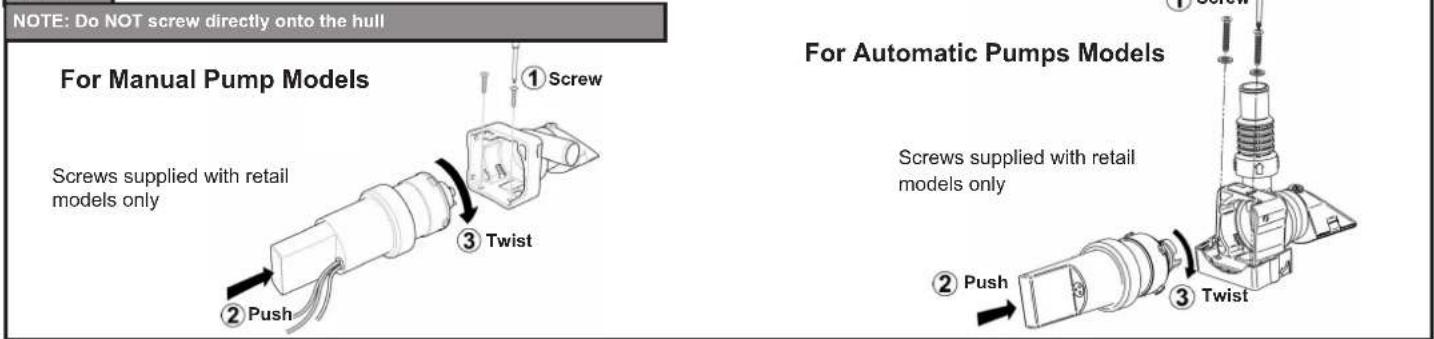
- In order to securely fasten the unit, ensure that the mounting surface is a minimum thickness of 19mm (3/4") (screws supplied with retail models only). NOTE Do not screw directly to the hull - must be mounted on a bulkhead or on an additional board.
- NOTE - DO NOT unscrew the rear section, as interference with the internal electrics will render the pump unfit for use. - this is a non-serviceable part of the pump.
- WARNING: Fire hazard. Wiring must comply with applicable electrical standards and include a properly rated fuse or circuit breaker. Improper wiring can cause a fire resulting in injury or death. Switch off the power while making connections.
4. Optional Extras
LV1219 Non-Return Valve (recommended for SS5012 models).
BE9003 / BE9006 Automatic, water activated, electronic switch (For use with SS5012, SS5022, SS1012 and SS1024 models).
BE9002 Automatic, water activated, floatswitch (Please see Figure 5, Supersub Automatic System).
SF5131 3/4" Skin fitting (for use with SS5012, SS5022 and SS5212 models)
SF5204 1" Skin Fitting (for use with SS1012, SS1024, SS1212 and SS1224 models)
5. Installation Instructions
See diagrams (page 4)
6. Instructions for Use
SS5012, SS5022, SS1012 and SS1024 - Manual System:
Step 1: When fitted on their own, these pumps must be activated by putting the switch into the ON position (Figure 5, Supersub Manual System). Step 2: The Supersub must be turned off as soon as the water has been evacuated from the bilge, as running the pump when it is dry will shorten the life of the pump.
SS5012, SS5022, SS1012 and SS1024 - Automatic System:
Step 1: When used with BE9002, BE9003 or BE9006 the pump can be left on automatic or switched to manual activation (Figure 5, Supersub Automatic System).
SS5212, SS1212 and SS1224:
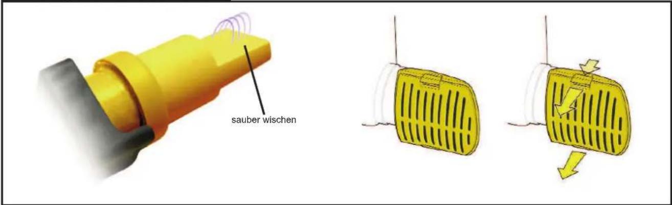
Step 1: Set the 3 way switch to Automatic (Figure 5 Supersub Smart 650/1100), the pump will run when necessary. Place fingers over sensor area to check pump is activated (wait 5 seconds), remove fingers and wait for the pump to stop (25 seconds). Check pump regularly to ensure no clogging occurs (Figure 7).
7. Trouble Shooting
PROBLEM POSSIBLE CAUSES POSSIBLE SOLUTIONS
| Limited flow | Blocked or dirty filter and / or impeller | Check for blockages in filter/impeller. Clean with warm soapy water (Do not use any chemical cleaning agents) |
| Blocked or dirty pipe work and/or connections | Disconnect pump and check flow through pipe work, unblock or clean as necessary | |
| Narrow pipe work or connections | Replace narrow aperture connections and any crushed or collapsed pipe work | |
| Low battery power Check battery level, refill or recharge as necessary | ||
| No flow | Completely blocked filter and / or impeller | Check for blockages in filter/impeller. Clean with warm soapy water (Do not use any chemical cleaning agents) |
| Blocked or dirty pipe work and/or connections | Disconnect pump and check flow through pipe work, unblock or clean as necessary | |
| Blown fuse Check above two remedies first. Replace with appropriate fuse | ||
| Flat battery | Check battery level, replace, refill or recharge as necessary | |
| Incorrectly located sensor | Consult Installation Instructions, available with product or on website | |
| Pump failure Check within 1 year warranty. Contact retailer and replace pump | ||
| Runs continuously | Switching error | Faulty on/off switch |
| Incorrectly located automatic switch | ||
| Faulty float switch/ electric field switch | ||
| Float switch stuck upright (Manual version) | Check there are no moving bodies within the bilge that may prevent movement of the float | |
| Ensure free movement of float switch | ||
| Electric field sensor remains activated | Wrong pump orientation, consult Installation Instructions, available with product or on website | |
| Check there are no moving bodies within the bilge that may cover the area where the sensor is located | ||
| Sensor too close to pipe work, boat structure or other body of mass | ||
| If there is thick debris on sensor - wipe clean | ||
8. Winterization
Freezing in winter may cause damage to the Supersub range of products. To avoid this damage, ensure water is removed from the bilge on a regular basis, especially before and during winter months.
9. Service Support & Warranty
The Supersub range is a non-serviceable product range. If the pump fails due to mishandling or if the product is outside of its warranty period, a new pump must be purchased. For full warranty statement please see document enclosed. Due to extreme conditions found in the bilge of boats, we recommend that your submersible bilge pump is replaced at least every 3 years, this is due to temperature changes and the different chemical environments. For installation or serviceable parts advice please contact Whale® Customer Support:
UK: Tel: +44 (0)28 9127 0531 Email: info@whalepumps.com www.whalepumps.com
USA: Tel: +1 (616) 897-2301 Email: usasales@whalepumps.com www.whalepumps.com
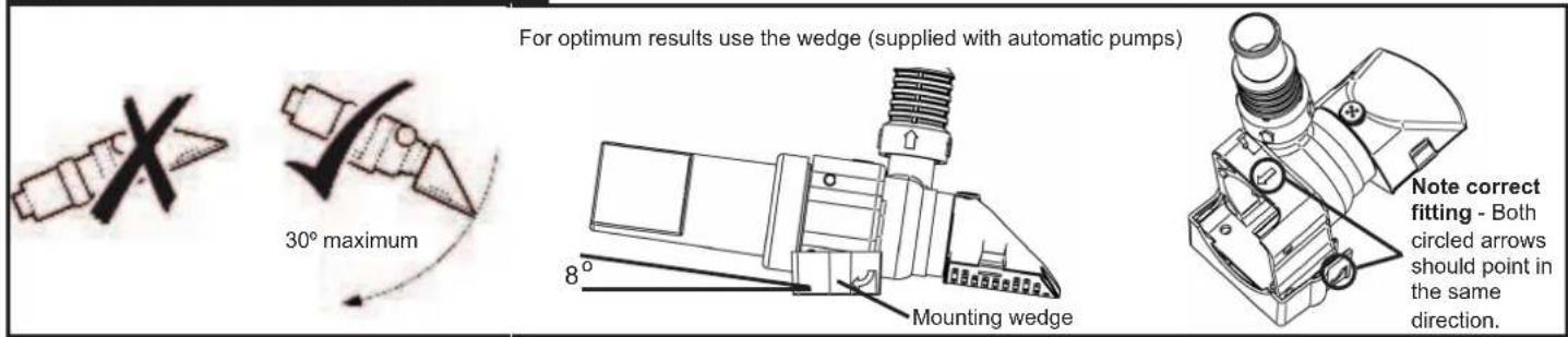
Figure 1. Installation Recommendations
text_image
For optimum results use the wedge (supplied with automatic pumps) 30° maximum Mounting wedge 8° Note correct fitting - Both circled arrows should point in the same direction.Figure 2. Fitting Instructions

text_image
Step 1 A Choose position A or B B Step 2 Twist 1 2 Pull Step 3 If supplied, fit wedge to suit chosen position (product is shipped in position B)Step 4
text_image
NOTE: Do NOT screw directly onto the hull For Manual Pump Models Screws supplied with retail models only ① Screw ② Push ③ Twist For Automatic Pumps Models Screws supplied with retail models only ② Push ③ TwistFigure 3. Advantage of Using Mounting Wedge Part When Retrofitting In Place Of Competitor Pumps (Supersub Smart only)

text_image
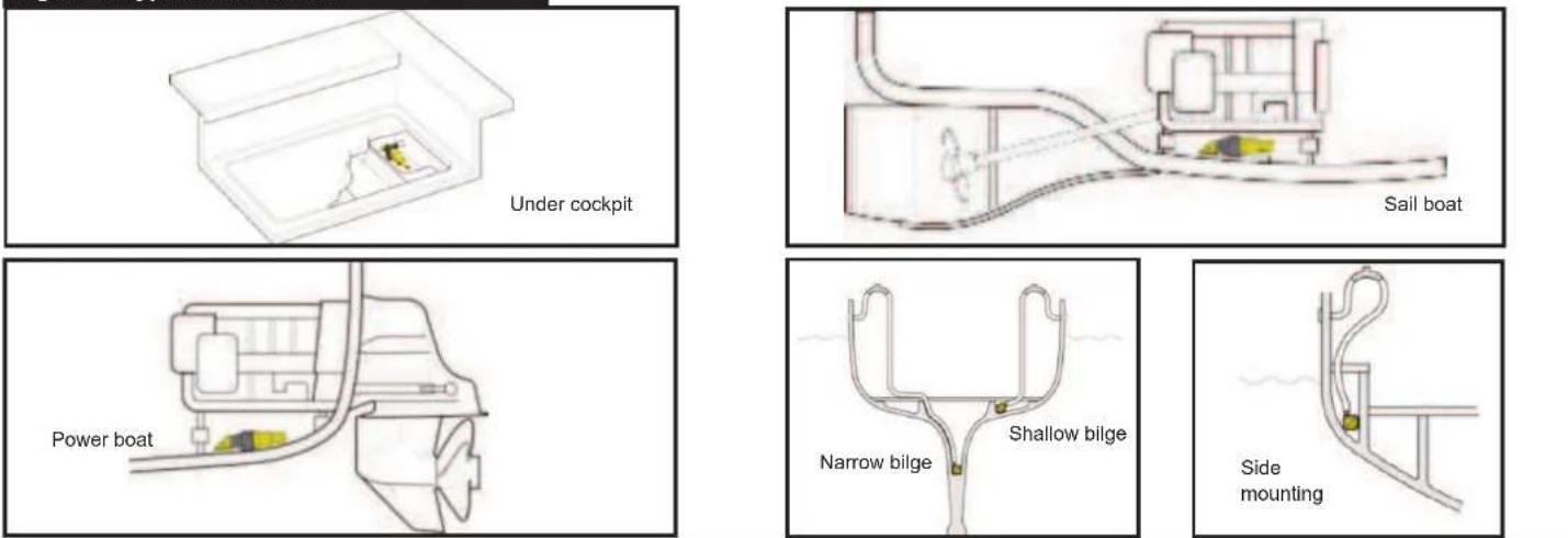
>ABS< Multiple hole options to retrofit in place of competitor pumps 8mm (5/16") (not included) for securing diffuser housing to wedge without affecting mounting surfaceFigure 4. Typical Installation
text_image
Under cockpit Sail boat Power boat Narrow bilge Shallow bilge Side mountingFigure 5. Wiring Diagrams
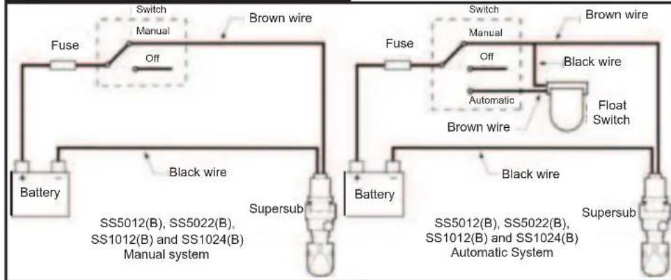
flowchart
graph TD
    subgraph Power Source
        A["Battery"] --> B["Switch Manual"]
        B --> C["Off"]
        C --> D["Brown wire"]
        D --> E["Black wire"]
        E --> F["Supersub"]
        F --> G["SS5012(B), SS5022(B), SS1012(B) and SS1024(B) Manual system"]
    end

    subgraph Power Supply
        H["Battery"] --> I["Switch Manual"]
        I --> J["Off"]
        J --> K["Brown wire"]
        K --> L["Black wire"]
        L --> M["Float Switch"]
        M --> N["Automatic"]
        N --> O["Black wire"]
        O --> P["Supersub"]
        P --> Q["SS5012(B), SS5022(B), SS1012(B) and SS1024(B) Automatic System"]
    end

    style Power Source fill:#f9f,stroke:#333
    style Supply fill:#bbf,stroke:#333
Supersub
text_image
Switch Automatic Brown wire Off White wire Manual Black wire Battery Supersub Smart SS5212(B), SS1212(B) and SS1224(B)Supersub Smart
Figure 6. Plumbing
text_image
SS5012(B) - 19mm (3/4") SS5022(B), SS5212(B) - 19mm (3/4") / 25mm (1") SS1012(B), SS1024(B), SS1212(B), SS1224(B) - 25mm (1") / 28mm (1 1/8") Anti-Syphan Loop 19mm (3/4") Pipe Boat Hull Jubilee Clip Skin Fitting Retaining NutFigure 7. Maintenance
text_image
Wipe clean10. Declaration of Conformity, Standards, Approvals
This product complies with all relevant European directives and standards. Please contact Whale® if further details are required
Manufacturer's Declaration
We hereby declare, under our sole responsibility, that the enclosed equipment complies with the provisions of the following relevant EU legislation.
Electromagnetic Compatibility Directive 2014/30/EU.
Recreational Craft Directive 2013/53/EU.
RoHS II Directive 2011/65/EU.
Based on the following harmonized standards:
EN55014-1:2006+A2:2011 EMC Emissions
EN55014-2:1997+A2:2008 EMC Immunity
EN28846:1993+A1:2000 Ignition Protection
ISO 8849:2003 Electrically Operated Bilge Pumps
ISO 15083:2003 Small Craft - Bilge Pumping Systems
And therefore complies with the essential requirements of that directive.
This product also conforms to the following standards:
ABYC H22, 2011 Electric Bilge Pump Systems
Date: 29 May 2017
Richard Bovill
Engineering Director
©Copyright Whale 2018 - All rights reserved. Reproduction in whole or in part without permission is prohibited.
WHALE®, is a registered trademark of Munster Simms Engineering Limited, Bangor, Northern Ireland trading as Whale. Whale's policy is one of continuous improvement and we reserve the right to change specifications without prior notice. Illustrations are for guidance purposes only.
Neither the accuracy nor completeness of the information contained in this or any product literature is guaranteed by the Company and may be subject to change at its sole discretion.
5. Instructions D'Installation
SS5212, SS1212 et SS1224:
SYMPTOMES CAUSES POSSIBLES SOLUTIONS
natural_image
Line drawing of a hand holding a small object, with a building and architectural sketch in the background (no text or symbols)natural_image
Technical line drawing of an electrical insulator assembly (no text or symbols)
natural_image
Technical line drawing of a mechanical housing with two screws inserted (no text or symbols)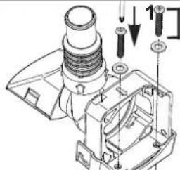
text_image
Technical diagram of a mechanical assembly with labeled parts and directional arrows indicating assembly stepsManufacturer's Déclaration
SS5212, SS1212 et SS1224:
natural_image
Technical line drawing of a mechanical housing component with two screws inserted (no text or symbols)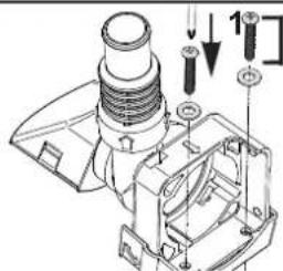
text_image
Technical diagram of a mechanical assembly with labeled parts and directional arrows indicating assembly stepsSS5212, SS1212 y SS1224:
PROBLEMA POSIBLES CAUSAS SOLUCION
natural_image
Line drawing of a hand holding a small object, with a small building visible in the background (no text or symbols)text_image
Technical diagram of a mechanical assembly with labeled parts and directional arrows indicating motion or assembly steps.natural_image
Technical line drawing of a mechanical housing with two screws inserted (no text or symbols)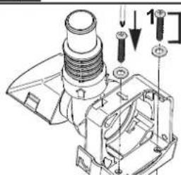
text_image
Technical diagram of a mechanical assembly with labeled parts and directional arrows indicating motion or force vectors.natural_image
Simple line drawing of a box with a small inset showing a yellow object, labeled 'En cabina' (no other text or symbols)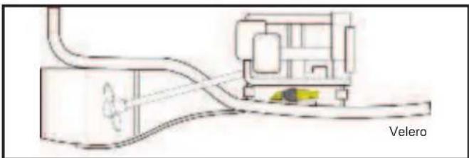
natural_image
Diagram of a vehicle or industrial device connected to a control panel, with no visible text or symbols.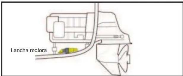
text_image
Lancha motora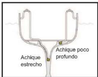
text_image
Achique estrecho Achique poco profundo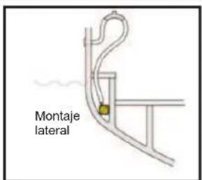
text_image
30° maximumnatural_image
Technical line drawing of a mechanical assembly with no visible text or symbolsnatural_image
Technical line drawing of a mechanical device with no visible text or symbolsnatural_image
Line drawing of a hand holding a small object, with architectural details visible above (no text or symbols)natural_image
Technical line drawing of a mechanical housing with two screws inserted (no text or symbols)
text_image
Technical diagram of a mechanical assembly with labeled parts and directional arrows indicating motion or forcetext_image
SS5012(B) - 19mm (3/4") SS5022(B), SS5212(B) - 19mm (3/4") / 25mm (1") SS1012(B), SS1024(B), SS1212(B), SS1224(B) - 25mm (1") / 28mm (1 1/8") Anti-Siphon- Schleife Rumpf Schlauch schelle 19mm (3/4") Rahr Decksdurchbruch KonlermutterAbb. 7 Pflege
natural_image
Diagram of a 3D box with an internal object and label 'Under cockpit' (no other text or symbols)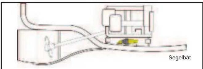
natural_image
Diagram of a vehicle connected to a fuel pump, showing internal components and wiring (no text or symbols)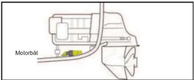
text_image
Motorbát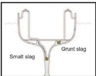
text_image
Smalt slag Grunt slag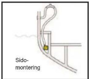
text_image
Sido- monteringBild 5. Elscheman
flowchart
graph TD
    subgraph Left_Busit
        A["Batteri"] --> B["svart kabel"]
        B --> C["Supersub"]
        D["Brytare"] --> E["Manuell"]
        E --> F["brun kabel"]
        G["Off"] --> H["Säkring"]
        H --> I["Batteri"]
        J["Brytare"] --> K["Manuell"]
        K --> L["brun kabel"]
        M["Off"] --> N["Säkring"]
        N --> O["Brutto"]
        P["Automatisk"] --> Q["brun kabel"]
        Q --> R["Nivåvakt"]
    end
    subgraph Right_Busit
        S["Batteri"] --> T["svart kabel"]
        T --> U["Supersub"]
        V["Brytare"] --> W["Manuell"]
        W --> X["brun kabel"]
        Y["Off"] --> Z["Säkring"]
        Z --> AA["Brutto"]
        AB["Automatisk"] --> AC["brun kabel"]
        AD["Nivåvakt"] --> AE["Nivåvakt"]
    end
    style Left_Busit fill:#f9f,stroke:#333
    style Right_Busit fill:#bbf,stroke:#333
Supersub
text_image
Brytare Säkring Automatisk Off brun kabel vit kabel Manuell svart kabel Batteri Supersub Smart SS5212(B), SS1212(B) och SS1224(B)Supersub Smart
Bild 6. Rördragning
text_image
SS5012(B) - 19mm (3/4") SS5022(B), SS5212(B) - 19mm (3/4") / 25mm (1") SS1012(B), SS1024(B), SS1212(B), SS1224(B) - 25mm (1") / 28mm (1 1/8") Coque du bateau Anneau de serrage Anti-sifonloop 19mm (3/4") rôr Passe-coque Contre-écrouBild 7. Underhåll
text_image
Borsta renSS5212, SS1212 ja SS1224:
text_image
Moottorivene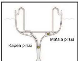
text_image
Kapea pilssi Matala pilssi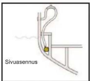
©Copyright Whale 2018 - All rights reserved.
All rights reserved. Reproduction in whole or in part without permission is prohibited.
WHALE®, is a registered trademark of Munster Simms Engineering Limited, Bangor, Northern Ireland trading as Whale. Whale's policy is one of continuous improvement and we reserve the right to change specifications without prior notice. Illustrations are for guidance purposes only.
Neither the accuracy nor completeness of the information contained in this or any product literature is guaranteed by the Company and may be subject to change at its sole discretion.
Whale - Munster Simms Engineering Ltd.
2 Enterprise Road, Bangor, N. Ireland BT19 7TA
Tel: +44 (0)28 9127 0531
Web: www.whalepumps.com
Email: info@whalepumps.com
Whale (The Americas)
Tel: +1 616 897 9241
Web: www.whalepumps.com
Email: usasales@whalepumps.com