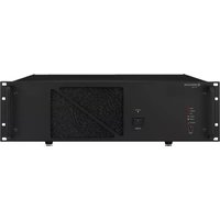
PA-1960 - Hi-fi system Monacor - Free user manual and instructions
Find the device manual for free PA-1960 Monacor in PDF.


User questions about PA-1960 Monacor
0 question about this device. Answer the ones you know or ask your own.
Ask a new question about this device
Download the instructions for your Hi-fi system in PDF format for free! Find your manual PA-1960 - Monacor and take your electronic device back in hand. On this page are published all the documents necessary for the use of your device. PA-1960 by Monacor.
USER MANUAL PA-1960 Monacor
text_image
Fault Detector OSC Level min max. Sensitivity PA-6FD COM HOT Line in Sense a b c d etext_image
SPEAKER OUTPUTS COM 1 2 3 COM HOT (a) - Line In - (b)High-Power PA Amplifier
These instructions are intended for installers with specific knowledge in 100V technology for PA applications. Please read the instructions carefully prior to installation and keep them for later reference.
All operating elements and connections described can be found on the fold-out page 3.
Contents
1 Operating Elements and Connections 7
1.1 Front panel 7
1.2 Rear panel....7
2 Safety Notes 7
3 Applications....8
4 Installation of Additional Modules . .8
4.1 Fault detection module PA-6FD ..... 8
4.1.1 Installation and connection ..... 8
4.1.2 Calibration....8
4.2 Fault monitoring module PA-6FM .....8
5 Setting Up the Amplifier .....8
5.1 Rack installation .....9
6 Connecting the Amplifier .....9
6.1 Speakers 9
6.2 Line signal inputs. 9
6.3 100V input .....9
6.4 Priority relay and 24V output .....9
6.5 Remote-controlled activation/deactivation 9
6.6 Power supply and emergency power supply. 9
7 Operation....9
8 Protective Circuit 9
9 Specifications 9
1 Operating Elements and Connections
1.1 Front panel
1 Volume control PGM for the signal at the PGM INPUT (12)
2 LED PRIORITY: will light up when the amplifier is switched over to the PRIORITY INPUT (17) via the terminal PRI CTL (15)
3 Power LED
4 LED SIGNAL: will light up when a certain volume has been reached at the SPEAKER OUTPUTS (9)
5 LEDs for fault indication
FAULT will light up if a fault has occurred in the amplifier
PROTECT will light up if the amplifier is overheated or a fault has occurred in the amplifier
CLIP will light up in case of overload of the amplifier [turn back volume control PGM (1) or LEVEL (16)]
6 POWER switch
Note: If a 24 V voltage from an emergency power supply unit is applied to the terminals BATTERY (21), it will not be possible to switch off the amplifier.
7 LED STANDBY: will light up if the amplifier is connected to the 230 V mains supply, if it is switched off with the POWER switch (6) and no 24 V voltage is applied to the terminals BATTERY (21)
8 Air intake openings for the fan
1.2 Rear panel
Note: To facilitate handling when screwing on the connection cables, all green terminal strips can be disconnected from their plug-in connections.
9 Speaker terminals
Important! Due to the factory settings of the amplifier, the terminals COM and 3 must be used for 100 V speakers.
10 The relay contacts will switch over if the amplifier is switched over to the PRIORITY INPUT (17) via the terminal PRI CTL (15)
11 Alternative SLAVE INPUT for connection to a 100 V speaker cable
12 Balanced line signal input PGM INPUT for standard announcements and background music; sensitivity for rated output power 0.775 V (0 dBu)
13 DIP switches
No. 1 to activate/deactivate the 400 Hz high-pass filter (will attenuate the bass frequencies to improve the speech intelligibility)
No. 2 lower position ON (factory setting) if the fault detection module PA-6FD (accessory) is not installed upper position OFF if the module is installed
No. 3 to activate / deactivate the 20 kHz test tone if the module PA-6FD is installed (see chapter 4.1.1, step 6)
14 LED indicator; will light up when the amplifier operates correctly
15 Terminal OUT for the 24 V output (voltage is always applied when the amplifier is switched on; current rating 0.5 A) and terminal PRI CTL for a priority switch: if the priority switch is closed, the amplifier will switch over from the PGM INPUT (12) to the PRIORITY INPUT (17)
16 Volume control LEVEL for the signal at the PRIORITY INPUT (17)
17 Balanced line signal input PRIORITY INPUT for important announcements – also see items 15 and 16; sensitivity for rated output power 0.775V (0dBu)
18 Cover plate, to be removed when inserting the fault monitoring module PA-6FM
19 Cover plate, to be removed when inserting the fault detection module PA-6FD
20 Air outlets
21 Terminals BATTERY for a 24 V emergency power supply unit
22 Terminals POWER REMOTE for an external switch for remote-controlled activation / deactivation
Note: For remote control, the amplifier must not be switched on with the POWER switch (6).
23 Mains cable for connection to a mains socket (230 V/50 Hz)
2 Safety Notes
This unit corresponds to all relevant directives of the EU and is therefore marked with €€
WARNING

The unit is supplied with hazardous mains voltage. Leave servicing to skilled personnel only and never insert anything into the air vents; you will risk an electric shock!
During operation, there is a hazard of contact with a voltage of up to 100 V at the terminals SPEAKER OUTPUTS (9) and SLAVE INPUT (11). Always switch off the PA system before making or changing any connections.
- The unit is suitable for indoor use only. Protect it against dripping water and splash water, high air humidity and heat (admissible ambient temperature range 0–40°C).
- Do not place any vessel filled with liquid on the unit, e. g. a drinking glass.
- The heat generated within the unit must be carried off by air circulation. Therefore, do not cover the air vents of the housing.
-
Do not operate the unit and immediately disconnect the mains plug from the socket
-
in case of visible damage to the unit or to the mains cable,
- if a defect might have occurred after the unit was dropped or suffered a similar accident,
- if malfunctions occur.
In any case the unit must be repaired by skilled personnel.
- A damaged mains cable must be replaced by skilled personnel only.
- Never pull the mains cable for disconnecting the mains plug from the socket, always seize the plug.
- For cleaning only use a dry, soft cloth; never use water or chemicals.
- No guarantee claims for the unit and no liability for any resulting personal damage or material damage will be accepted if the unit is used for other purposes than originally intended, if it is not correctly connected or operated, or if it is not repaired in an expert way.
- Important for UK Customers!
The wires in this mains lead are coloured in accordance with the following code:
green/yellow=earth
blue = neutral
brown = live
As the colours of the wires in the mains lead of this appliance may not correspond with the
coloured markings identifying the terminals in your plug, proceed as follows:
- The wire which is coloured green and yellow must be connected to the terminal in the plug which is marked with the letter E or by the earth symbol 12 or coloured green or green and yellow.
- The wire which is coloured blue must be connected to the terminal which is marked with the letter N or coloured black.
- The wire which is coloured brown must be connected to the terminal which is marked with the letter L or coloured red.
Warning – This appliance must be earthed.

If the unit is to be put out of operation definitively, take it to a local recycling plant for a disposal which is not harmful to the environment.
3 Applications
The amplifier PA-1960 with an RMS output power of 960 W is specially designed for applications in PA systems. A line level input is provided for background music and standard announcements; a second line level input is provided for emergency announcements or other important announcements. By means of a separate switch or an external relay, it is possible to switch over to the second input.
The PA-1960 is also easily integrated into an existing PA system if more power is required for further speakers. For this purpose, it is equipped with a 100 V input.
4 Installation of Additional Modules
The amplifier can be extended by the following additional modules from MONACOR:
PA-6FD fault detection module
PA-6FM fault monitoring module
WARNING

Additional modules must always be installed by skilled personnel. Prior to opening the amplifier, disconnect the mains plug from the socket, otherwise you will risk an electric shock!
If an emergency power supply unit is connected, disconnect it from the terminals BATTERY (21) to ensure that the amplifier is out of operation.
4.1 Fault detection module PA-6FD
The fault detection module PA-6FD available as an accessory is specially designed for this amplifier. It will generate a 20 kHz sinusoidal test tone which is fed to the power amplifier. If the test tone is not applied to the SPEAKER OUTPUTS (9) due to a defect in the amplifier, the LEDs FAULT and PROTECT (5) will light up. Furthermore, the green LED (14) on the rear side of the amplifier will go out. Via a relay, a signal device can be activated in addition.
4.1.1 Installation and connection
text_image
ON OFF SW 1 CN601 PA-6FD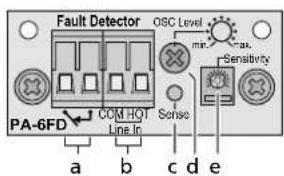
text_image
Fault Detector OSC Level min. max. Sensitivity PA-6FD COM HOT Line In Sense a b c d e1) Unscrew the housing cover of the amplifier and remove the cover plate (19). Disconnect the 4-pole cable that is fixed to the cover plate.
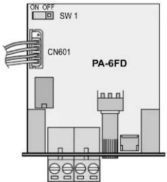
2) Set the jumper SW 1 on the module to the position ON.
3) Insert the module at the position of the cover plate from the outside and screw it on.
4) Connect the 4-pole cable that was fixed to the cover plate to the jack CN 601 of the module. Make sure that the upper pin of the jack is not connected, see figure of the module.
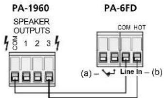
5) Connect the terminal strip SPEAKER OUTPUT (9) of the amplifier to the terminal strip "Line In" (b) of the module as follows:
text_image
PA-1960 SPEAKER OUTPUTS COM 1 2 3 PA-6FD COM HOT (a) Line In - (b)6) Set DIP switch No. 2 (13) on the rear side of the amplifier to the upper position OFF and DIP switch No. 3 to the lower position ON.
However, if the SLAVE INPUT (11) is used and a 20 kHz test tone from another amplifier is already applied here, set DIP switch No. 3 to the upper position OFF, otherwise two test tones will be superposed!
7) If the module detects a fault, the LEDs FAULT and PROTECT (5) will light up and the relay contacts ↘(a) will close. The contacts allow connection of a signal device for alarm triggering. The current rating of the relay contacts is 1A at \~120V max. or =24V max.
Note: The relay contacts will also close when the amplifier is switched off.
4.1.2 Calibration
An oscilloscope or a voltmeter is required which is able to measure alternating voltage up to 20kHz min.
1) Switch on the amplifier and set the volume controls PGM (1) and LEVEL (16) to zero so that only the 20 kHz test tone is applied to the speaker outputs.
If the SLAVE INPUT (11) is used, no signal of an announcement or no music signal must be applied to this input while calibrating; only a 20 kHz test tone from another amplifier, if necessary. If a 20 kHz test tone is applied, skip the next step and proceed with step 3.
2) Measure the voltage of the 20 kHz test tone at the contacts COM and 3 of the SPEAKER OUTPUTS (9). Use the trimmer potentiometer OSC Level (d) to set the level to 2 V (5.6 Vpp).
3) Turn up the trimmer potentiometer Sensitivity (e) until the LED Sense (c) lights up. From this position, turn the potentiometer to the scale mark after the next. The LED may flicker during operation; this is not a fault.
4) After calibrating, set the controls PGM (1) and LEVEL (16) back to the desired volume.
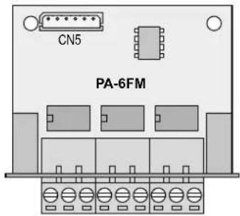
4.2 Fault monitoring module PA-6FM
text_image
CN5 PA-6FM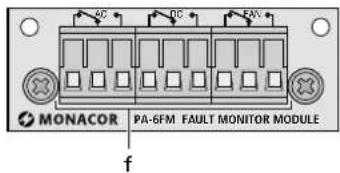
text_image
AC DC FAV MONACOR PA-6FM FAULT MONITOR MODULE fThe fault monitoring module PA-6FM available as an accessory is specially designed for this amplifier. The three relay outputs (f) allow activation of signal devices in case of the following faults:
The relay contacts AC will switch over if no mains voltage is applied, if the internal mains fuse has blown, or if the amplifier has not been switched on with the POWER switch (6).
The relay contacts DC will switch over if the internal fuses for the emergency power supply have blown or if no voltage from an emergency power supply unit is applied to the terminals BATTERY (21).
The relay contacts FAN will switch over if the internal fan is defective or not connected.
Note: All relay contacts will also switch over when the amplifier is switched off.
1) Unscrew the housing cover of the amplifier and remove the cover plate (18). Disconnect the 6-pole cable fixed to the cover plate from the plate.
2) Lead the 6-pole cable which was fixed to the cover plate outwards through the new opening created and connect it to the jack CN 5 of the module.
3) Insert the module PA-6FM at the position of the cover plate from the outside and screw it down.
4) Connect the signal devices for alarm triggering to the switch-over relay contacts (f). The marking on the module shows the contact position in case of defect and with the amplifier switched off. The current rating of the relay contacts is 1 A at \~ 120 V max. or = 24V max.
5 Setting Up the Amplifier
The amplifier is provided for installation into a rack for units with a width of 482 mm (19"), but it can also be used as a table top unit. In any case, make sure that air will circulate freely through all vents to provide a sufficient cooling of the power amplifier.
5.1 Rack installation
For rack installation, 3 RS (3 rack spaces = 133 mm) are required. To prevent the rack from becoming top-heavy, insert the amplifier into the lower section of the rack. The front panel alone is not sufficient for fixing it safely. In addition, lateral rails or a bottom plate must secure the unit.
The hot air given off by the amplifier must be dissipated from the rack; otherwise heat will accumulate in the rack which may not only damage the amplifier but also other units in the rack. In case of insufficient heat dissipation, install a ventilation unit into the rack (e.g. DPVEN-04).
6 Connecting the Amplifier
Any connection should only be made by skilled personnel. Always switch off the amplifier before connecting!
Note: To facilitate handling when screwing on the connection cables, all green terminal strips can be disconnected from their plug-in connections.
6.1 Speakers
Connect the PA speakers to the terminal strip SPEAKER OUTPUTS (9): connect the negative poles to the contact COM and the positive poles to the contact 1, 2, or 3 corresponding to the nominal voltage of the speakers. The total load by the speakers must not exceed 960 W RMS, otherwise the amplifier will be damaged.
Important! Due to the factory settings of the amplifier, the terminals COM and 3 must be used for 100 V speakers.
The table below shows any nominal voltages possible:
| Jumper in position | Terminal | ||
| 1 2 3 | |||
| AFactory setting | 75V8 | 5V100V | |
| B 60V70V85V | |||
| C 50V60V75V | |||
WARNING

Modification of the factory settings must only be made by skilled personnel. Prior to opening the amplifier, disconnect the mains
plug from the socket, and if an emergency power supply unit is connected, disconnect it from the terminals BATTERY (21), otherwise you will risk an electric shock!
Unscrew the housing cover of the amplifier. A wire jumper is provided on the PCB with the terminals SPEAKER OUTPUTS (9) and PRIORITY RELAY (10). Rearrange the jumper from contact A to contact B or C. Screw down the housing cover again.
6.2 Line signal inputs
For announcements and music reproduction, a PA preamplifier is required (e. g. PA-1414MX from MONACOR) which allows to connect microphones and audio units (e. g. CD player, radio set). Connect the output of the preamplifier to the PGM INPUT (12).
For emergency announcements or other important announcements, the PA-1960 is equipped with the PRIORITY INPUT (17). As soon as a priority switch or a relay connected to the terminals PRI CTL (15) is closed, the amplifier will switch over from the PGM INPUT to the PRIORITY INPUT and only the emergency announcement will be audible. The volume for emergency announcements is separately adjusted with the control LEVEL (16) on the rear side.
6.3 100V input
As an alternative to the line signal inputs (12) and (17), the 100 V SLAVE INPUT (11) can be used, e. g. to provide additional power for further speakers for an existing PA system. Connect the terminals SLAVE INPUT to the 100 V speaker cable of the PA system.
Note: The controls PGM (1) and LEVEL (16) will not affect the volume of the signal applied to the SLAVE INPUT. Adjust the signal volume on the amplifier which will feed the 100 V signal to the PA-1960.
6.4 Priority relay and 24 V output
As soon as a priority switch or a relay connected to the terminals PRI CTL (15) is closed, the internal priority relay will switch over. Its terminals PRIORITY RELAY (10) allow to control further actions, e. g. switching PA attenuators with emergency priority relay to maximum volume.
If a 24 V voltage is required for switching the emergency priority relays, e. g. the voltage from the terminal +24 V (15) may be routed via the relay contacts. The 24 V voltage has a current rating of 500 mA and can also be used for other applications.
6.5 Remote-controlled activation/deactivation
The amplifier allows remote-controlled activation / deactivation via a separate switch.
1) Connect the terminals POWER REMOTE (22) via a two-pole cable to a single-pole on / off switch.
2) For remote-controlled activation/deactivation, the amplifier must not be switched on with the POWER switch (6).
6.6 Power supply and emergency power supply
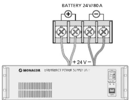
1) For continued operation of the amplifier in case of mains failure, connect a 24 V emergency power supply unit (e. g. PA-24ESP from MONACOR) to the terminals BATTERY (21). The amplifier must be connected to the emergency power supply unit via four cables (fig.). For each cable, with a maximum cable length of 4 m, a minimum cable cross section of 5 mm ^2 is required (e. g. CPC-... series from MONACOR).
Note: If the 24 V voltage from the emergency power supply unit is applied to the terminals BATTERY, it will not be possible to switch off the amplifier with the POWER switch (6). In case of mains failure or when switched off, the amplifier will automatically switch to the emergency power supply.
text_image
BATTERY 24V/80A +24 V - MONACOR EMERGENCY POWER SUPPLY UNIT2) Finally connect the mains plug of the connection cable (23) to a socket (230 V/ 50 Hz).
Note: Even when the amplifier is switched off, it will have a low power consumption. Therefore, disconnect the mains plug from the socket and, if necessary, disconnect the emergency power supply unit if the amplifier is not operated for a longer period.
7 Operation
If the amplifier is switched off and the mains voltage is applied, the LED STANDBY (7) will light up.
1) To prevent switching noise, switch on all other units of the PA system first.
2) Prior to switching on the amplifier for the first time, set the controls PGM (1) and LEVEL (16) to zero so that there will be no excessive volume to start with. Then switch on the amplifier with the POWER switch (6) or a switch connected to the terminals POWER REMOTE (22). The POWER LED (3) will light up.
3) Set the control PGM (1) to the desired volume. When a certain volume is reached, the LED SIGNAL (4) will light up. In case of overload, the red LED CLIP (5) will light up. In this case, reduce the volume with the control.
4) Adjust the volume for important announcements fed to the amplifier via the PRIORITY INPUT (17) with the control LEVEL (16) on the rear side of the unit. For this purpose, the priority switch (or the relay) connected to the terminals PRI CTL (15) must be closed. The LED PRIORITY (2) will light up.
5) To improve speech intelligibility, switch on a high-pass filter (400 Hz) with DIP switch No. 1(13) [position ON]. Thus, low-frequency interference will be suppressed.
8 Protective Circuit
The amplifier is equipped with a protective circuit against overheating, overload and short circuit at the speaker outputs. In case of overheating, the LED PROTECT (5) will light up; in case of overload, short circuit or another defect, the LED FAULT will additionally light up. In any case, the amplifier will be muted. If one of these LEDs light up, switch off the amplifier and have the fault eliminated by skilled personnel.
If the fault detection module PA-6FD (chapter 4.) is not installed, set DIP switch No. 2 (13) on the rear side of the amplifier to the lower position ON, otherwise the protective circuit will respond.
9 Specifications
Rated power.... 960W
THD: < 0.4%
Output voltage/
output impedance: ..... 75V/5.6Ω
85V/7.2Ω
100V/10Ω
Inputs
PGM + PRIORITY INPUT: 0.775 V/60 kΩ
SLAVE INPUT: ..... 100V
Frequency range: ..... 35–20 000 Hz, -3 dB
S/N ratio: .... > 100 dB (A weighted)
High-pass filter:....400 Hz, 6 dB/octave
Power supply
Mains voltage: 230V/50Hz
Power consumption: .. 2600VA
Emergency power supply: 24 V(---)/80 A
Ambient temperature: .. 0–40°C
Dimensions (W × H × D): 482 × 133 × 374 mm, 3 RS (rack spaces)
Weight: 25 kg
Subject to technical modification.
All rights reserved by MONACOR® INTERNATIONAL GmbH & Co. KG. No part of this instruction manual may be reproduced in any form or by any means for any commercial use.
text_image
PA-1960 SPEAKER OUTPUTS COM 1 2 3 PA-6FD COM HOT (a) - Line In - (b)text_image
ON OFF SW 1 CN601 PA-6FD Fault Detector OSC Level min Smax. Sensitivity PA-6FD COM HOT Sense Line in a b c d etext_image
PA-1960 SPEAKER OUTPUTS COM 1 2 3 PA-6FD COM HOT (a) - Line In - (b)text_image
PA-1960 SPEAKER OUTPUTS COM 1 2 3 PA-6FD COM HOT (a) - Line in - (b)1.1 Panel Frontal.... 19
1.2 Panel posterior.... 19
text_image
SPEAKER OUTPUTS COM 1 2 3 (a) — Line In — (b) COM HOTtext_image
SPEAKER OUTPUTS COM 1 2 3 COM HOT (a) - Line In - (b)Wymiary (W × H × D):... 482 × 133 × 374mm, 3 U
Waga: 25 kg