PAM224 - Hi-fi system Monacor - Free user manual and instructions
Find the device manual for free PAM224 Monacor in PDF.
User questions about PAM224 Monacor
0 question about this device. Answer the ones you know or ask your own.
Ask a new question about this device
Download the instructions for your Hi-fi system in PDF format for free! Find your manual PAM224 - Monacor and take your electronic device back in hand. On this page are published all the documents necessary for the use of your device. PAM224 by Monacor.
USER MANUAL PAM224 Monacor
Matrix Zone Mixing Amplifier with 8 Inputs
text_image
CLP CLP CLP CLP CLP CLP CLP CLP CLP CLP CLP CLP CLP CLP CLP CLP CLP CLP CLP CLP CLP CLP CLP CLP CLP CLP CLP CLP CLP CLP CLP CLP CLP CLP MONACOR PA-M412 POWERtext_image
OUTPUT ZONE 2 ZONE 1 PAGING INC WALL MODULE WALL MODULE LINE LIME SPEAKER SPEAKER FULL AUTO ALL 10.5 10.4 10.3 10.2 10.1 10.0 19.8-20.6 19.7-20.4 19.5-20.2 19.3-20.0 19.1-20.0 18.9-20.0 18.7-20.0 18.5-20.0 18.3-20.0 18.1-20.0 17.9-20.0 17.7-20.0 17.5-20.0 17.3-20.0 17.1-20.0 16.9-20.0 16.7-20.0 16.5-20.0 16.3-20.0 16.1-20.0 15.9-20.0 15.7-20.0 15.5-20.0 15.3-20.0 15.1-20.0 14.9-20.0 14.7-20.0 14.5-20.0 14.3-20.0 14.1-20.0 13.9-20.0 13.7-20.0 13.5-20.0 13.3-20.0 13.1-20.0 12.9-20.0 12.7-20.0 12.5-20.0 12.3-20.0 12.1-20.0 11.9-20.0 11.7-20.0 11.5-20.0 11.3-20.0 11.1-20.0 10.9-20.0 10.7-20.0 10.5-20.0 10.3-20.0 10.1-20.0 9.9-20.0 9.7-20.0 9.5-20.0 9.3-20.0 9.1-20.0 8.9-20.0 8.7-20.0 8.5-20.0 8.3-20.0 8.1-20.0 7.9-20.0 7.7-20.0 7.5-20.0 7.3-20.0 7.1-20.0 6.9-20.0 6.7-20.0 6.5-20.0 6.3-20.0 6.1-20.0 5.9-20.0 5.7-20.0 5.5-20.0 5.3-20.0 5.1-20.0 4.9-20.0PA-M224
text_image
28 ON ACTIVE 30 PWM 29 FUSH R LINE 31 Mic MONACOR TM-MLNTPA-M1WP
text_image
32 33 34 OUTPUT PLUOCL LIOK MIN MAX 35 FLESH 36 CUP ○ SIGNAL ○ POWER 37 38 ALL □ 39 □ 1 □ 2 1 □ 3 2 □ 4 2 CH 4 CH MONACOR PA-MARC CHIME □ □ 1ALK 40 41PA-M4RC
English ...... Page 9
Français ...... Page 14
Matrix Zone Mixing Amplifier
These instructions are intended for installers with specific knowledge of sound reproduction using 100 V technology and for users without any specific knowledge (chapters 2 and 7). Please read these instructions carefully prior to operation and keep them for later reference.
The figures relating to the text below can be found on page 2.
Contents
1 Overview 9
1.1 Front panel ..... 9
1.2 Rear panel 9
1.3 Wall module PA-M1WP ..... 10
1.4 Zone paging microphone PA-M4RC 10
2 Safety Notes 10
3 Applications....10
4 Setting up the Amplifier ..... 10
4.1 Rack installation ..... 10
5 Connecting the Amplifier ..... 11
6 Basic Settings 11
7 Operation 12
7.1 Adjusting volume and sound ..... 12
7.2 Changing input signals for the zones 12
7.3 Muting zones....12
7.4 Monitoring zone signals ..... 12
7.5 Zone paging microphone PA-M4RC 12
7.5.1 Saving a zone selection for further announcements ..... 12
7.6 Wall module PA-M1WP ..... 12
7.7 Malfunctions ..... 12
8 Specifications ..... 13
1 Overview
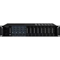
1.1 Front panel
1 Equalizer controls HIGH, MID and LOW; one each for the inputs CH 1 to CH 4
2 Volume controls for the corresponding input signal; one each for the inputs CH 1 to CH8
3 LED indicators CLIP and SIG; one each for the inputs CH 1 to CH 8
CLIP: Will light up briefly to indicate that the maximum undistorted signal level has been reached. If it lights up more frequently, the input is overloaded; in this case, turn back the control GAIN (21) accordingly
SIG: Will light up when a specific signal level has been reached at the corresponding input
4 Zone buttons Z 1 and Z 2 (PA-M412: Z 1 - Z 4) to switch the input signal to the PA zone(s) desired; one each for the inputs CH 1 to CH 8
5 Equalizer controls HIGH and LOW for the individual PA zones
6 LED indicators for the individual PA zones
PROT: Will light up when, in case of overheating or overload, the protective circuit has switched off the speakers
CLIP: Will light up briefly to indicate that the maximum undistorted signal level has been reached. If it lights up more frequently, the zone is overloaded; in this case, turn back the control ZONE (8) accordingly
0, -10, SIG: Level indicators for the zone
7 Buttons MUTE to mute the individual zones
8 Controls ZONE to adjust the volume in the individual zones
9 Selector switch PFL/AFL for the monitor function with the monitor speaker (12)
PFL: The zone selected will be monitored ahead of the volume control ZONE (8); the signal will be audible even when the volume control is turned to minimum or when the button MUTE (7) is pressed
AFL: The zone will be monitored after the volume control ZONE
10 Buttons Z 1 and Z 2 (PA-M412: Z 1 – Z 4) to select the zone to be monitored via the monitor speaker (12)
11 Volume control MONITOR for the monitor speaker (12)
12 Monitor speaker to monitor the zones
13 Power switch and LED indicator POWER
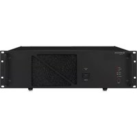
1.2 Rear panel
14 Mains jack for connection to a mains socket (230 V/50 Hz) via the mains cable supplied
15 Mains fuse Always replace a blown fuse by one of the same type!
16 RJ 45 jack PAGING MIC for a zone paging microphone PA-M4RC
17 Connection MUTE ALL for a switch to mute all zones at the same time
18 RJ 45 jacks WALL MODULE; one each for a wall module PA-M1WP per zone
19 Line level outputs of the individual zone signals, e. g. to connect additional amplifiers
20 Speaker connections for the zones The power rating for each zone is PA-M224: 240 W PA-M412: 120 W
Caution! The total load of the speakers connected in a zone must not exceed the rated power of the zone.
21 Controls GAIN to adjust the input gain; one each for the inputs CH 1 to CH 8 When the gain is too high, the corresponding LED indicator CLIP (3) will light up frequently for high signal levels; in this case, turn back the control accordingly.
22 Mono inputs LINE (6,3 mm jacks) for the connection of audio units with line level (e. g. microphone preamplifier) CH1–4 balanced CH5–8 unbalanced
23 Stereo inputs LINE (RCA jacks) of the inputs CH 5–8 for the connection of audio units with line level (CD / MP3 player, radio, etc.)
24 XLR jacks MIC of the inputs CH 1 - 4 for the connection of microphones
25 On / Off switch PHANTOM 2-4 for the phantom power supply of the microphone inputs MIC (24) in the channels CH2-4
Caution! Only use this switch when the amplifier has been switched off or when the corresponding volume control (2) has been set to minimum (switching noise).
Never connect a microphone with an unbalanced output when phantom power has been activated. The microphone may be damaged.
26 On / Off switch AUTOTALK for the talkover function of the input CH 1
When an announcement is made while the switch is in the position ON, the other
inputs will be muted and the announcement will be routed to all zones; the zone buttons Z.. (4) in the channel CH 1 will have no function.
27 On / Off switch PHANTOM for the phantom power supply of the microphone MIC (24) in the channel CH 1 Please observe the "Caution" note of item 25.
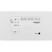
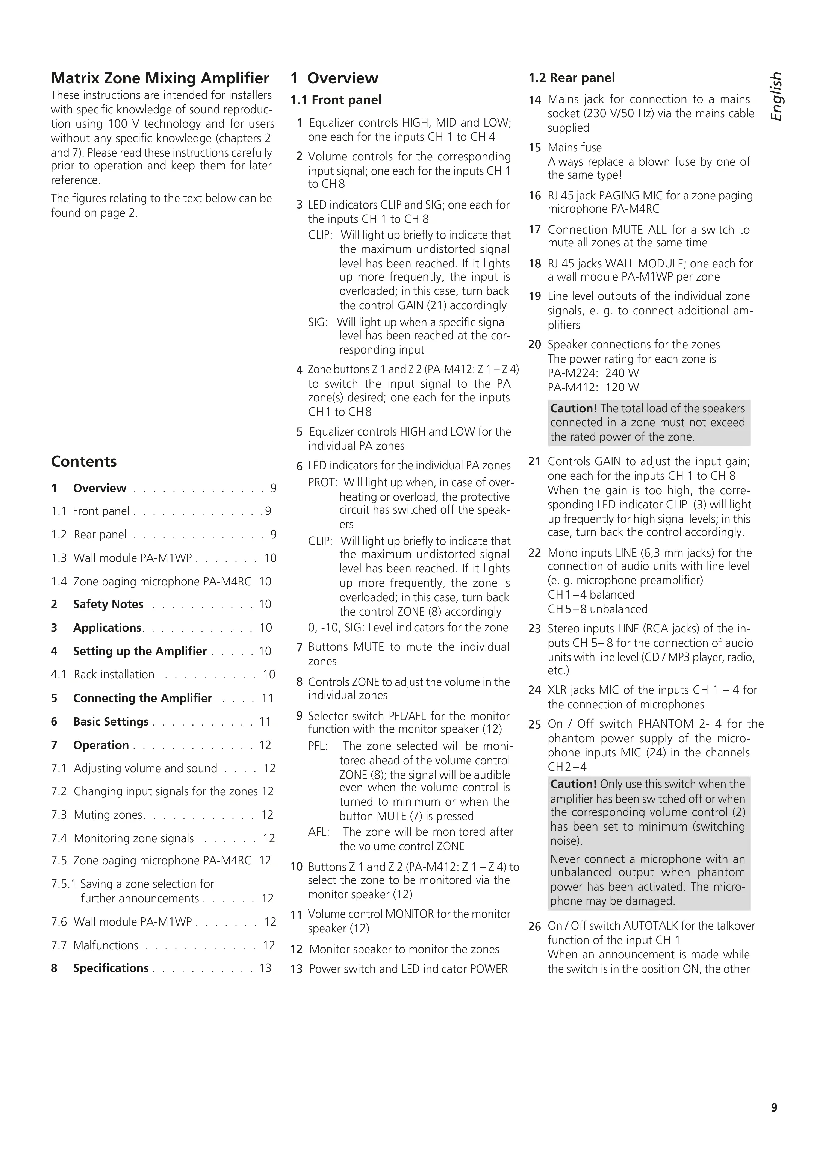
1.3 Wall module PA-M1WP
The wall module is available as an accessory and is not supplied with the amplifier. The wall module can be used to adjust the volume directly in the PA zone and to provide audio signals to the zone.
On the rear side of the module, a RJ45 jack is available designed for connection to the jack WALL MODULE (18) of the amplifier via a Cat 5e cable (copper conductors, not copper-clad aluminium conductors) with a length of up to 200 m.
28 Signal selector button with LED indicator Button engaged: The LED indicator will light up in yellow; the signal routed to the jacks MIC (29) or LINE (31) will be audible Button disengaged: The LED indicator will light up in green; the signal selected at the amplifier for this zone will be audible
29 XLR jack MIC for connection of a microphone
Caution! A 14 V phantom power is always available at this jack; therefore, never connect a microphone with an unbalanced output, it may be damaged.
30 Volume control for the zone The maximum volume possible can be adjusted by means of the corresponding control ZONE (8) at the amplifier.
31 RCA jacks LINE to provide a line signal
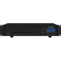
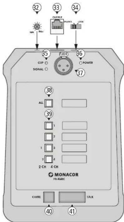
1.4 Zone paging microphone PA-M4RC
The zone paging microphone is available as an accessory and is not supplied with the amplifier.
32 Volume control for the microphone signal
33 RJ45 jack OUTPUT for connection to the jack PAGING MIC (16) of the amplifier via a Cat 5e cable (copper conductors, not copper-clad aluminium conductors) with a length of up to 200 m
34 Selector switch LOCK/UNLOCK to save a zone selection
UNLOCK: The zone selection for an announcement will be deleted after the announcement has been made and the button TALK (41) is not pressed anymore. For the next announcement, the zones must again be selected with the corresponding buttons (38 or 39).
LOCK: When the selector switch is set to LOCK after the zones have been selected, the selection will remain saved.
35 LED indicator CLIP: Will light up briefly to indicate that the maximum undistorted signal level has been reached. If it lights up more frequently, the microphone signal is distorted; in this case, turn back the volume control (32) accordingly. LED indicator SIGNAL: Will light up when the volume of the announcement has reached a specific level
36 LED indicator POWER
37 XLR jacks for connection of the gooseneck microphone supplied
38 Button ALL for announcements in all zones
39 Buttons to select the zones in which an announcement shall be audible
Note: Please note the different lettering of the zone buttons: the digits 1 and 2 to the left of the buttons apply to the amplifier PA-M224, the digits 1 – 4 to the right of the buttons apply to the amplifier PA-M412.
40 Button CHIME to precede the announcement by a chime tone
41 Button TALK
2 Safety Notes
The unit corresponds to all relevant directives of the EU and is therefore marked with €€ The unit corresponds to the relevant UK legislation and is therefore marked with UKCA.
WARNING

The unit uses dangerous mains voltage. Leave servicing to skilled personnel and never insert anything into the air vents. Risk of electric shock!
During operation, there is a hazard of contact with a dangerous voltage of up to 100 V at the speaker terminals SPEAKER (20). Always switch off the amplifier before making or changing any connections!
- The unit is suitable for indoor use only. Protect it against dripping water, splash water and high air humidity. The admissible ambient temperature range is 0 – 40 °C.
- Do not place any vessel filled with liquid on the units, e. g. a drinking glass.
- The heat generated inside the unit must be dissipated by air circulation; never cover the air vents of the housing.
- Immediately disconnect the unit from the mains socket,
- if the unit or the mains cable is visibly damaged,
- if a defect might have occurred after the unit was dropped or suffered a similar accident,
- if malfunctions occur.
In any case the unit must be repaired by skilled personnel.
- Never pull the mains cable to disconnect the mains plug from the socket, always seize the plug.
- For cleaning only use a dry, soft cloth; never use water or chemicals.
- No guarantee claims for the unit and no liability for any resulting personal damage or material damage will be accepted if the unit is used for other purposes than originally intended, if it is not correctly connected or operated, or if it is not repaired in an expert way.

If the unit is to be put out of operation definitively, dispose of the unit in accordance with local regulations.
3 Applications
This amplifier has specially been designed for setting up a PA system in which individual areas or rooms (zones) can be provided with sound in different ways. The signals of eight different audio sources (microphones, MP3/ CD player, radio, etc.) can be routed as desired to two zones (with the amplifier PA-M224) or to four zones (with the amplifier PA-M412). For each zone, the volume and the sound can be adjusted differently as required.
The wall module PA-M1WP (accessory) can be used to adjust the volume directly in a zone. It is possible to connect a microphone or an MP3 player, for example, to the wall module so that, instead of the signal source selected at the amplifier, the microphone/MP3 player is audible in the zone.
By means of the zone paging microphone PA-M4RC (accessory), announcements can be made in a specific zone or in all zones.
4 Setting up the Amplifier
The amplifier is designed for installation into a rack for units of a width of 482 mm (19") but can also be used as a tabletop unit. In order to ensure sufficient cooling of the amplifier, air must always be able to flow freely through all air vents.
4.1 Rack installation
For rack installation, the amplifier requires 2 RS (2 rack spaces = 89 mm). To prevent the rack from becoming top-heavy, insert the amplifier into the lower section of the rack. The front plate is not sufficient for fixing the amplifier safely; additionally use lateral rails or a bottom plate to secure the amplifier.
The hot air given off by the amplifier must be dissipated from the rack; otherwise heat will accumulate in the rack which may not only damage the amplifier but also other units in the rack. In case of insufficient heat dissipation, install a ventilation unit (e.g. DPVEN-04) into the rack.
5 Connecting the Amplifier
Connections should only be made by skilled personnel. Always switch off the amplifier before making any connection!
The amplifier is supplied with the corresponding screw terminal strips for the green plug-in connections (17, 19, 20).
| Unit | Connection Note |
| Inputs | |
| Microphone for announcements in all zones | XLR jack MIC (24) of CHANNEL 1Set the switch TALK-OVER (26) to ON. |
| Microphones for announcements in different zones and for other applications | XLR jacks MIC (24)For connection to CHANNEL 1, set the switch TALKOVER (26) to OFF. |
| Mono audio units with line level, e. g. microphone amplifier | 6.3 mm jacks LINE (22) |
| Stereo audio units with line level, e. g. CD/ MP3 player, radio | RCA jacks LINE (23) |
| Switch to mute all zones at the same time | Green plug-in connection MUTE ALL (17) |
| Outputs | |
| 100V speaker | Green plug-in connection SPEAKER (20) for each zoneThe rated power of the zone is PA-M224: 240 WPA-M412: 120 Wand must not be exceeded! |
| Additional PA amplifier when more speakers than allowed are required | Green plug-in connection LINE (19) for each zone |
| Accessory | |
| Zone paging microphone PA-M4RC | RJ45 jack PAGING MIC (16)* |
| Wall module PA-M1WP | RJ 45 jack WALL MODULE (18)* for each zone |
| * via Cat 5e cable (with copper conductors, not copper-clad aluminium conductor) with a length of up to 200 m | |
Finally, use the mains cable supplied to connect the mains jack (14) of the amplifier to a mains socket (230V/50Hz).
6 Basic Settings
1) To avoid switching noise, first switch on all the other units of the PA system.
2) Before first-time operation of the amplifier, set the volume controls ZONE (8) to minimum to make sure that the volume will not be too high after switch-on. Then switch on the amplifier by means of the POWER switch (13). The LED indicator POWER will light up.
3) For basic setting of the input channels:
a) Turn all controls GAIN (21), HIGH, MID and LOW (1) to mid-position.
b) Turn all volume controls CH .. (2) to minimum.
c) Disengage all zone buttons Z .. (4).
d) When a microphone for announcements in all zones has been connected to the input CH 1, set the switch TALKOVER (26) to the position ON. Thus, while an announcement is being made, all other inputs will be muted and the announcement will be routed to all zones; the zone buttons Z .. (4) in the input CH 1 will have no function.
If the input CH 1 is not used for announcements in all zones, set the switch TALKOVER to the position OFF.
e) Activate or deactivate the phantom power supply for the microphone inputs MIC (24).
Caution! There may be loud switching noise while the phantom power supply is being activated or deactivated. Therefore, set the volume controls ZONE (8), for example, to minimum first.
Never connect a microphone with an unbalanced output to an input where the phantom power supply has been activated. The microphone may be damaged.
When a microphone that requires phantom power has been connected to the input CH 1, set the switch PHANTOM (27) to the position ON; in all other cases, set the switch to the position OFF.
When microphones that require phantom power have been connected to the inputs CH 2 - 4, set the switch PHANTOM 2-4 (25) to the position ON; in all other cases, set the switch to the position OFF.
4) Turn the volume control CH .. (2) of the input to be reproduced at the highest volume to approx. 23 of its maximum. Use the zone buttons Z .. (4) to switch the input signal to the zones in which it is to be audible.
5) Use the controls ZONE (8) to adjust the volume desired for each zone. The level indicators (6) will indicate the volume of the zones. The yellow LED indicator CLIP should only light up briefly for signal peaks. If it lights up more frequently, turn back the corresponding control ZONE accordingly.
If the volume of the input signal is too low or too high so that it is not possible to adjust the volume of the zone in an optimum manner, readjust the input level by means of the corresponding control GAIN (21) or CH .. (2). If the LED indicator CLIP (3) in an input channel lights up more frequently, the input is overloaded. In this case, turn back the control GAIN accordingly. The LED indicator CLIP may only light up briefly for signal peaks.
6) To route additional input signals to specific zones, press the corresponding zone buttons Z .. (4).
7) Use the buttons CH .. (2) to adjust the volume of the other input signals. Turn the controls of the inputs not used to minimum.
8) Use the controls HIGH, MID and LOW (1) to adjust the sound of the input signals in the channels CH 1–4.
Use the controls HIGH and LOW (5) to match the sound in the individual zones to the respective room acoustics.
7 Operation
7.1 Adjusting volume and sound
To increase or reduce the volume for a zone, turn the corresponding control ZONE (8) up or down. To readjust the sound for a zone, use the corresponding controls (5): HIGH for the high frequencies, LOW for the low frequencies.
If the volume of an input signal is too high or low in relation to the volume of other input signals, readjust the volume by means of the corresponding control CH .. (2). The sound of an input signal in the channels CH 1 – 4 can be adjusted by means of the controls HIGH, MID and LOW (1).
Important: The settings for an input signal will apply to all zones to which the input signal has been switched.
7.2 Changing input signals for the zones
If other signals than the ones currently selected are to be audible in the zone:
1) In all input channels, disengage the corresponding zone button Z .. (4) for the zone (e. g. to change the selection for zone 2, disengage the buttons Z 2). Thus, all signals for the zone are deselected for the time being.
2) Press the zone buttons Z .. in the input channels whose signals are to be audible in the zone.
3) If required, readjust the volume for the zone by means of the corresponding control ZONE (8).
7.3 Muting zones
If a zone is not to be provided with sound (e.g. during intervals or at the end of an event), the sound can be muted by means of the corresponding button MUTE (7).
Muting the sound of a zone can also be useful when input signals are being selected: Even when the sound of a zone is muted, the sound can be monitored via the monitor speaker (12), see chapter 7.4. Thus it is possible to make tests by switching input signals to a zone without them being audible there.
7.4 Monitoring zone signals
A monitor speaker (12) is available so that zone signals can be directly monitored at the amplifier:
1) Use the switch PFL/AFL (9) to make the appropriate selection:
PFL = The zone signals will be audible via the monitor speaker even when the button MUTE (7) is pressed or when the volume control ZONE (8) is set to minimum.
AFL = The signals will be audible according to the zone volume adjusted.
2) Engage the zone button Z .. (10) of the zone to be monitored. Disengage the other zone buttons (10).
3) Use the control MONITOR (11) to adjust the volume for the monitor speaker.
7.5 Zone paging microphone PA-M4RC
Connect the microphone to the amplifier and then, to make the basic settings, turn the control (32) on the rear of the microphone to mid-position and set the sliding switch (34) to the position UNLOCK. As soon as the amplifier is switched on, the LED indicator POWER (36) will light up.
1) First use the zone buttons 1 ... 4 (39) to select the zones in which the announcement shall be audible. To select all zones, press the button ALL (38); to deselect a zone, press a button again.
Note: Please note the different lettering of the microphone for the zones: the digits 1 and 2 to the left of the buttons apply to the amplifier PA-M224, the digits 1 – 4 to the right of the buttons apply to the amplifier PA-M412.
2) Press the button CHIME (40) if the announcement is to be preceded by a chime tone.
3) To make an announcement, keep the button TALK (41) pressed, wait for the chime tone (if applicable) and then speak into the microphone. The LED indicator CLIP (35) should only light up briefly. If it lights up more frequently, turn the control (32) counter-clockwise accordingly, speak at a lower volume or increase the distance to the microphone.
If the volume of the announcement is too low, turn the control clockwise accordingly, speak at a higher volume or reduce the distance to the microphone.
4) After the announcement, release the button TALK; the zone selection will be deleted; the zones must be selected again for the next announcement.
Note: Announcements made via the zone paging microphone will take priority over other signals and will interrupt them.
7.5.1 Saving a zone selection for further announcements
1) Select the zones by means of the buttons (38, 39).
2) Set the sliding switch (34) to the position LOCK. It will not be possible to change the zone selection.
3) To make an announcement, keep the button TALK (41) pressed. When the button TALK is released, the zone selection will remain saved, the corresponding zone buttons will remain illuminated. The selection will also remain saved when the amplifier is switched off.
To change a zone selection saved:
1) Set the sliding switch (34) to the position UNLOCK.
2) Use the buttons (38, 39) to select and de-select zones.
3) To save a zone selection changed, set the sliding switch (34) to the position LOCK again.
7.6 Wall module PA-M1WP
As soon as the module is connected to the amplifier and the amplifier is switched on, the LED indicator ACTIVE of the module will light up.
1) Use the button (28) of the module to make the appropriate selection:
- The signals of a microphone or audio unit (CD player, radio, etc.) connected to the module are to be audible in the zone: Engage the button; the LED indicator ACTIVE will light up in yellow.
- The signals selected at the amplifier by means of the buttons Z .. (4) are to be audible in the zone: Disengage the button; the LED indicator ACTIVE will light up in green.
2) Use the control VOL (30) to adjust the volume for the zone. If it is not possible to adjust a sufficiently high volume, turn up the corresponding control ZONE (8) at the amplifier which defines the maximum volume possible.
7.7 Malfunctions
If the amplifier stage of a zone is overheated or overloaded, the protective circuit will interrupt the signal path to the speaker terminal SPEAKER (20) in this zone. In this case, no signal will be audible in the zone and the corresponding LED indicator PROT (6) will light up.
Use the corresponding control ZONE (8) to reduce the zone volume. If the LED indicator PROT fails to extinguish after the amplifier stage has cooled down, ask skilled personnel to find and eliminate the fault.
8 Specifications
| Amplifier PA-M224 PA-M412 | ||
| Number of input channels 8 8 | ||
| Number of zones 2 4 | ||
| Rated output power 2 × 240 W 4 × 120 W | ||
| THD < 1% < 1% | ||
| Zone outputs | 2 × speaker 100 V | 4 × speaker 100 V |
| 2 × line signal | 4 × line signal | |
| Connection | Screw terminals | Screw terminals |
| Phantom power supply for Mic CH 1 – 4 24V24V | ||
| Inputs | Input sensitivity/Impedance; connection | |
| Mic CH 1–4 | 2.5 – 380 mV*/20 kΩ; XLR, balanced | |
| Line CH 1–4 | 30–2000 mV*/20 kΩ; 6.3 mm, balanced | |
| Line CH 5–8 | 30–2000 mV*/20 kΩ; RCA and 6.3 mm, unbalanced *gain max.–gain min. | |
| Frequency range | 20–20000 Hz | |
| Equalizers for the inputs CH 1 – 4 | ||
| Low frequencies | ±12 dB/80 Hz | |
| Midrange frequencies | ±12 dB/2.5 kHz | |
| High frequencies | ±12 dB/12.5 kHz | |
| Equalizers for the zones | ||
| Low frequencies | ±15 dB/80 Hz | |
| High frequencies | ±15 dB/12 kHz | |
| S/N ratio | >70 dB | |
| Type of power amplifier | Class D | |
| Ambient temperature | 0–40°C | |
| Power supply | 230 V/50 Hz | 230 V/50 Hz |
| Power consumption | 800 VA max. | 860 VA max. |
| Dimensions (W × H × D) | 482 × 88 × 320 mm, 2 RS | 482 × 88 × 320 mm, 2 RS |
| Weight | 5.7 kg | 6.2 kg |
| Zone paging microphone | PA-M4RC |
| Type | Electret microphone |
| Frequency range | 45–15 000 Hz |
| Sensitivity | 1 mV/Pa |
| Power supply | via PA-M224, PA-M412 |
| Ambient temperature | 0–40°C |
| Dimensions of the base (W × H x D) | 140 × 65 × 205 mm |
| Gooseneck length | 420 mm |
| Weight | 860 g |
| Connection | RJ45 jack |
| Wall module | PA-M1WP |
| Inputs1 × Mic1 × Line | Input sensitivity/Impedance; connection3 mV/20 kΩ; XLR, balanced420mV/30kΩ; RCA, unbalanced |
| Phantom power supply for Mic | 14V, cannot be deactivated |
| Power supply | via PA-M224, PA-M412 |
| Ambient temperature | 0–40°C |
| Dimensions (W × H × D) | 80 × 80 × 50 mm |
| Weight | 90g |
| Connection | RJ45 jack |
Subject to technical modification.
All rights reserved by MONACOR® INTERNATIONAL GmbH & Co. KG. No part of this instruction manual may be reproduced in any form or by any means for any commercial use.