PA1250D - Hi-fi system Monacor - Free user manual and instructions
Find the device manual for free PA1250D Monacor in PDF.
| Product Type | Public Address Amplifier (hi-fi system) |
| Brand | Monacor |
| Model | PA1250D |
| Rated Power (RMS) | 250 W |
| Music Power | 350 W |
| Speaker Output | 100 V, minimum load impedance: 40 Ω |
| Inputs | 1.2 V, 30 kΩ, balanced (PGM IN and PRIORITY IN) |
| Frequency Response | 50 - 18,000 Hz, ±3 dB |
| Signal-to-Noise Ratio | > 100 dB (A-weighted) |
| High-Pass Filter | 200 Hz, 6 dB/octave (enabled/disabled via menu) |
| Mains Power Supply | 230 V / 50 Hz |
| Mains Power Consumption | 350 VA max, 8 W standby |
| Backup Power Supply | 24 V DC (dedicated screw terminal) |
| Backup Power Consumption | 20 A max, 280 mA standby |
| Operating Temperature | 0 - 40 °C |
| Dimensions (W × H × D) | 482 × 88 × 410 mm (2U rack) |
| Weight | 7.5 kg |
| Main Functions | Remote management via RS-485/Modbus, priority input, automatic standby, battery monitoring, protection against overload, short circuit and overheating, microprocessor reset |
| Maintenance and Cleaning | Use a dry, soft cloth. Do not use chemicals or water. |
| Safety | Do not open the device. Dangerous voltage up to 100 V at speaker terminals. Disconnect before any intervention. Indoor use only. |
| Spare Parts and Repairability | Replaceable fuse (identical type). For any repair, contact a specialized technician. |
| Included Accessories | Power cord, removable screw terminals |
Frequently Asked Questions - PA1250D Monacor
User questions about PA1250D Monacor
0 question about this device. Answer the ones you know or ask your own.
Ask a new question about this device
Download the instructions for your Hi-fi system in PDF format for free! Find your manual PA1250D - Monacor and take your electronic device back in hand. On this page are published all the documents necessary for the use of your device. PA1250D by Monacor.
USER MANUAL PA1250D Monacor
| - DIGITAL AMP - |
| Communication ID: 0 |
| Baudrate: 9600 BPS |
| VER-2.2 (2016/09/23) |
| ⑤ | Infomenü 1, Knopf PUSH/LEVEL (8) drücken Info menu 1, press knob PUSH/LEVEL (8) Menu info 1, appuyez sur le bouton PUSH/LEVEL (8) Menu info 1, premere la manopola PUSH/LEVEL (8) Menu info 1, pulse el botón PUSH/LEVEL (8) Menu informacyjne 1, wcisnámPokretto PUSH/LEVEL (8) |
| ⑥ | Infomenü 2, Taste ENTER/INFO (4) drücken Info menu 2, press button ENTER/INFO (4) Menu info 2, appuyez sur la touche ENTER/INFO (4) Menu info 2, premere il tasto ENTER/INFO (4) Menu info 2, pulse el botón ENTER/INFO (4) Menu informacyjne 2, wcisné przycisk ENTER/INFO (4) |
Priority InputPriority Input Be Careful..
AMP SleepingAMF Sleeping Be Careful..
PC Line CheckAC Line Check LOW VOLTAGE
VOLUME STATUS [..] [DC LOW]
Battery Check Battery Check LOW VOLTAGE
VOLUME STATUS [..] [DC LOW]
OUER TEMPOVER TEMP mited Output
AMP FAULTAMP FAULT Please AMP Check
VOLUME STATUS [..] [Fault]
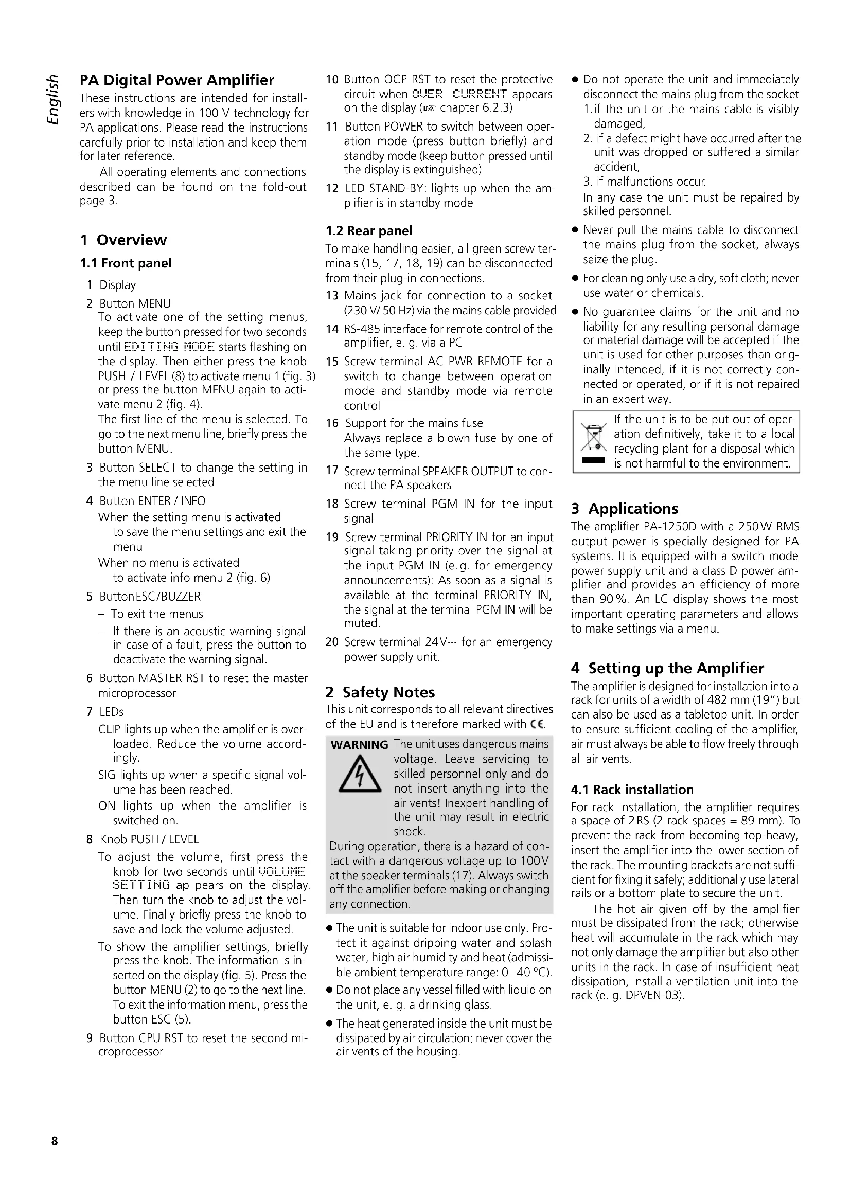
These instructions are intended for installers with knowledge in 100V technology for PA applications. Please read the instructions carefully prior to installation and keep them for later reference.
All operating elements and connections described can be found on the fold-out page 3.
1 Overview
1.1 Front panel
1 Display
2 Button MENU
To activate one of the setting menus, keep the button pressed for two seconds until EDITING MODE starts flashing on the display. Then either press the knob PUSH / LEVEL (8) to activate menu 1 (fig. 3) or press the button MENU again to activate menu 2 (fig. 4).
The first line of the menu is selected. To go to the next menu line, briefly press the button MENU.
3 Button SELECT to change the setting in the menu line selected
4 Button ENTER / INFO
When the setting menu is activated to save the menu settings and exit the menu
When no menu is activated to activate info menu 2 (fig.6)
5 ButtonESC/BUZZER
- To exit the menus
If there is an acoustic warning signal in case of a fault, press the button to deactivate the warning signal.
6 Button MASTER RST to reset the master microprocessor
7 LEDs
CLIP lights up when the amplifier is overloaded. Reduce the volume accordingly.
SIG lights up when a specific signal volume has been reached.
ON lights up when the amplifier is switched on.
8 Knob PUSH / LEVEL
To adjust the volume, first press the knob for two seconds until VOLUME SETTING apears on the display Then turn the knob to adjust the volume. Finally briefly press the knob to save and lock the volume adjusted.
To show the amplifier settings, briefly press the knob. The information is inserted on the display (fig. 5). Press the button MENU (2) to go to the next line. To exit the information menu, press the button ESC (5).
9 Button CPU RST to reset the second microprocessor
10 Button OCP RST to reset the protective circuit when OVER CURRENT appears on the display (6.2.3)
11 Button POWER to switch between operation mode (press button briefly) and standby mode (keep button pressed until the display is extinguished)
12 LED STAND-BY: lights up when the amplifier is in standby mode
1.2 Rear panel
To make handling easier, all green screw terminals (15, 17, 18, 19) can be disconnected from their plug-in connections.
13 Mains jack for connection to a socket (230V / 50Hz) via the mains cable provided
14 RS-485 interface for remote control of the amplifier, e. g. via a PC
15 Screw terminal AC PWR REMOTE for a switch to change between operation mode and standby mode via remote control
16 Support for the mains fuse Always replace a blown fuse by one of the same type.
17 Screw terminal SPEAKER OUTPUT to connect the PA speakers
18 Screw terminal PGM IN for the input signal
19 Screw terminal PRIORITY IN for an input signal taking priority over the signal at the input PGM IN (e.g. for emergency announcements): As soon as a signal is available at the terminal PRIORITY IN, the signal at the terminal PGM IN will be muted.
20 Screw terminal 24V = 1 for an emergency power supply unit.
2 Safety Notes
This unit corresponds to all relevant directives of the EU and is therefore marked with C€
WARNING
The unit uses dangerous mains voltage. Leave servicing to skilled personnel only and do not insert anything into the air vents! Inexpert handling of the unit may result in electric shock.
During operation, there is a hazard of contact with a dangerous voltage up to 100V at the speaker terminals (17). Always switch off the amplifier before making or changing any connection.
The unit is suitable for indoor use only. Protect it against dripping water and splash water, high air humidity and heat (admissible ambient temperature range: 0 - 40^
- Do not place any vessel filled with liquid on the unit, e. g. a drinking glass.
The heat generated inside the unit must be dissipated by air circulation; never cover the air vents of the housing.
- Do not operate the unit and immediately disconnect the mains plug from the socket 1. if the unit or the mains cable is visibly damaged,
- if a defect might have occurred after the unit was dropped or suffered a similar accident,
- if malfunctions occur.
In any case the unit must be repaired by skilled personnel.
- Never pull the mains cable to disconnect the mains plug from the socket, always seize the plug.
- For cleaning only use a dry, soft cloth; never use water or chemicals.
- No guarantee claims for the unit and no liability for any resulting personal damage or material damage will be accepted if the unit is used for other purposes than originally intended, if it is not correctly connected or operated, or if it is not repaired in an expert way.

If the unit is to be put out of operation definitively, take it to a local recycling plant for a disposal which is not harmful to the environment.
3 Applications
The amplifier PA-1250D with a 250W RMS output power is specially designed for PA systems. It is equipped with a switch mode power supply unit and a class D power amplifier and provides an efficiency of more than 90% . An LC display shows the most important operating parameters and allows to make settings via a menu.
4 Setting up the Amplifier
The amplifier is designed for installation into a rack for units of a width of 482mm (19") but can also be used as a tabletop unit. In order to ensure sufficient cooling of the amplifier, air must always be able to flow freely through all air vents.
4.1 Rack installation
For rack installation, the amplifier requires a space of 2 RS (2 rack spaces = 89mm .To prevent the rack from becoming top-heavy, insert the amplifier into the lower section of the rack. The mounting brackets are not sufficient for fixing it safely; additionally use lateral rails or a bottom plate to secure the unit.
The hot air given off by the amplifier must be dissipated from the rack; otherwise heat will accumulate in the rack which may not only damage the amplifier but also other units in the rack. In case of insufficient heat dissipation, install a ventilation unit into the rack (e.g. DPVEN-03).
5 Connecting the Amplifier
All connections must be made by skilled personnel. Always switch off the amplifier before making any connection!
To make handling easier when screwing on the connection cables, all green screw terminals (15, 17, 18, 19) can be disconnected from their plug-in connections.
1) For making announcements and reproducing music, a PA preamplifier (e.g. PA-1414MX) is required which allows connection of microphones and audio units (e.g. CD player, radio). Connect the output of the preamplifier to the input PGM IN (18).
2) For making emergency announcements or other important announcements, the PA-1250D is equipped with the input PRIORITY IN (19). As soon as a line level signal is available at this input, the input PGM IN will be muted so that only the emergency announcement is audible.
3) Connect the PA speakers to the screw terminal SPEAKER OUTPUT (17). Make sure that the total load of the speakers does not exceed 250 W RMS; otherwise the protective circuit will respond and reduce the volume of the amplifier or mute it (www.chapter 6.2.3).
4) To ensure continued operation of the amplifier after mains failure, connect a 24V emergency power supply unit (e.g. PA-24ESP) to the screw terminal 24V = (20) .
5) For remote-controlledactivation/deactivation, connect a switch to the screw terminal AC PWR REMOTE (15).
6) For remote control of the amplifier (e.g. via a PC) and for showing the operating parameters of the amplifier on a display, an RS-485 interface is provided. For data transmission, the Modbus protocol is used (page 26).
Connect the PC to the jack RS 485 IN (14). To operate another unit by remote control, connect this unit to the jack RS 485 OUT.
7) Finally connect the mains cable provided to the mains jack (13) and then connect it to a socket (230V / 50Hz) .The LED STAND-BY (12) lights up.
6 Operation
1) Press the button POWER (11) to switch on the amplifier. The LED STAND-BY (12) is extinguished; the LED ON (7) lights up and the display (1) is illuminated. To switch off the amplifier (i.e. to switch the amplifier to the standby mode), keep the button POWER pressed until the display is extinguished.
Alternatively, switch on / off the amplifier by remote control via a switch connected to the screw terminal AC PWR REMOTE (15). When the amplifier has been switched on by remote control, the
display shows [REMOTE] beneath the line STATUS.
Note: The amplifier can only be switched on / off by remote control when it has not been switched on with the button POWER. To allow for remote-controlled activation / deactivation even though the amplifier has been switched on with the button POWER, open the connected switch and then keep the button POWER pressed until the LED STAND-BY lights up.
2) To adjust the volume, first press the knob PUSH / LEVEL (8) for two seconds until VOLUME SETTING appears on the display. Then turn the knob to adjust the volume. Finally briefly press the knob to exit the volume setting menu and to save and lock the volume adjusted.
The display indicates the volume adjusted:
VOLUME [00] [99]
When a specific volume has been reached, the green LED SIG (7) lights up. The red LED CLIP lights up when the amplifier is being overloaded; reduce the volume accordingly.
3) Make all other settings via the menu.
Note: When in a menu, press a button within 30 sec onds; otherwise the menu will be deactivated and any settings you may have made will be discarded.
a) Press the button MENU (2) for two seconds until EDITING MODE flashes on the display.
b) Press the knob PUSH / LEVEL. The setting menu appears (fig. 3).
c) The first menu line BATTERY? is selected. Use the button SELECT (3) to define if the voltage of an emergency power supply unit connected is to be monitored (YES) or not (NO).
Note: If you use the unit PA-24ESP from MONACOR for emergency power supply, deactivate monitoring (OFF). Since the 24 V power of the PA-24ESP is only available in case of a main's failure, the PA-1250D would report this as a fault even in normal mains operation.
d) To go to the next menu line, press the button MENU; to change the setting, press the button SELECT:
H_P_F? to activate/deactivate the high-pass filter (200Hz) for the input PGM IN (18)
HMP SLEEP? With the setting ON, the amplifier will automatically go to sleep (the message HMP Sleeping starts flashing on the display) if the input signal is missing for more than one minute. After four minutes without an input signal, the amplifier will change to the standby mode. As soon as a signal is available, the amplifier will be reactivated.
AMP CHECK? to activate/deactivate monitoring of the power amplifier. If no input signal is available at the amplifier, the power amplifier will be checked by means of a test signal (the interval of the test signals can be set). If a fault is
detected, the display will show the message HMP FAULT (see chapter 6.2.5).
Note: It is only possible to select the menu line AMP CHECK when the function AMP SLEEP has been deactivated. The function AMP CHECK is automatically deactivated when the function AMP SLEEP is activated.
Interval TINE to set the time intervals of the power amplifier checks (1/2 hour to 24 hours)
e) To save the settings and exit the menu, press the button ENTER (4). EDIT-ING save briefly flashes on the display; then the standard display reappears (fig. 1).
Note: You can exit the setting menu at any time by pressing the button ESC (5). Any settings you may have made will be discarded.
4) If the amplifier is connected to a PC, activate the second setting menu to define the unit ID and the baud rate:
a) Press the button MENU for two seconds until EDITING MODE flashes on the display.
b) Press the button MENU again to activate the second setting menu (fig. 4).
c) The first menu line Communication ID is selected. Use the button SELECT to define the unit ID.
d) Press the button MENU to go to the next menu line. Use the button SELECT to define the baud rate.
e) Press the button ENTER to save the settings and exit the menu.
5) Two info menus can be activated for viewing the settings (figs. 5 and 6): To activate info menu 1, press the knob PUSH/LEVEL; to activate info menu 2, press the button ENTER/INFO. Info menu 1 also shows the temperature of the heat sink (Temperature). Press the button MENU to go to the next menu line. To exit a menu, press the button ESC/BUZZER or wait for approx. 30 seconds until the menu automatically disappears.
6.1 Reset
If the amplifier cannot be operated properly anymore, reset the amplifier by means of the following two buttons:
MASTER RST (6) to reset the master microprocessor
CPU RST (9) to reset the second microprocessor
Additionally, the button OCP RST (10) is available which allows you to reset the protective circuit when OVER CURRENT appears on the menu (W chapter 6.2.3, paragraph "Overload").
IMPORTANT! Use a thin, non-conductive object to press the reset buttons. If the second microprocessor was reset by means of the button CPU RST, the master microprocessor must also be reset by means of the button MASTER RST for the amplifier to work properly.
6.2 Display Messages
The display indicates various operating modes and faults. If there is an acoustic warning signal in case of a fault, press the button BUZZER (5) to deactivate this signal.
6.2.1 Inputs
| Priority Input | Priority Input |
| Be Careful.. |
This message keeps flashing on the display as long as a signal is available at the input PRIOR-ITY IN (19). The input PGM IN (18) is muted.
| AMP SleepingAMF | Sleeping |
| Be Careful.. |
This message is displayed when the input signal is missing for one minute and ON has been set in the line AMP SLEEP? of setting menu 1. The amplifier is in the sleep mode. It is switched on again when the button ESC (5) or the knob PUSH / LEVEL (8) is pressed on when the input signal is available again.
If the signal is missing for four minutes, the amplifier will change to the standby mode and the LED STAND-BY (12) will flash. The amplifier will change from standby mode to operation mode as soon as an input signal is available or the button POWER (11) is pressed.
6.2.2 Power supply
| AC Line CheckAC LOW VOLTAGE | Line Check |
This message appears when the mains voltage falls below approx. 190V . In this case, the power amplifier is switched off.
| VOLUME | STATUS |
| [..] | [DC LOW] |
If the amplifier is connected to an emergency power supply unit and the mains voltage fails, the amplifier will switch to the emergency power supply. If the setting YES was selected in the line BATTERY? of setting menu 1, the display will alternately show [BATT.] and [Normal] beneath the line STATUS.
| Battery Check Battery Check LOW VOLTAGE |
This message appears when the voltage of the emergency power supply unit falls below approx. 21 V and the setting YES was selected in the line BATTERY? of setting menu 1. The standard display will reappear after approx. 30 seconds or when the button ESC (5) is pressed:
| VOLUME | STATUS |
| [..] | [DC LOW] |
The line beneath the line STATUS, however, will alternately show [DC LOW] and [Normal].
6.2.3 Overload
| SKP-LINE SHORTSKP-LINE SHORT Output MUTE |
This message appears when there is a short circuit at the speaker output. The speaker output is muted.
| OUER CURRENTOUER CURRENTProtection |
This message appears when the power consumption is too high (e.g. speaker output overloaded or fault in the amplifier). The standard display will reappear after approx. 30 seconds or when the button ESC (5) is pressed:
| VOLUME | STATUS |
| [..] | [0CP ON] |
The line beneath the line STATUS, however, will show [OCP ON]. The protective circuit has switched off the power amplifier. To find the fault, disconnect the screw terminal SPEAKER OUTPUT (17) and then press the button OCP RST (10), using a thin, non-conductive object. The power amplifier is switched on again. If no fault indication appears, the fault is due to the speaker cable or the speakers. If the fault indication reappears, the amplifier is defective and must be repaired.
6.2.4 Overheating
| OUER TEMPOVER Limited Output | TEMP |
This message appears when the amplifier is overheated (e.g. in case of insufficient heat dissipation). The output power is limited to 18 of the rated power. The standard display will reappear after approx. 30 seconds or when the button ESC (5) is pressed:
| VOLUME | STATUS |
| [..] | [LIMIT] |
The line beneath the line STATUS, however, will alternately show [LIMIT] and [HEATED]. If the temperature of the heat sink continues to rise, the speaker output will be muted and the following message will appear:
| OUERTEMP MUTEOUERTEMP MUTE Output Mute |
The standard display will reappear after approx. 30 seconds or when the button ESC (5) is pressed:
| VOLUME | STATUS |
| [..] | [MUTE] |
The line beneath the line STATUS, however, will alternately show [MUTE] and [HEATED]. As soon as the temperature is back to normal, the amplifier returns to the rated output power.
6.2.5 Amplifier fault
| AMP FAULTAMP FAULT Please AMP Check |
This message appears when the microprocessor of the PA-1250D has detected a fault in the power amplifier by means of a test signal. A self-test is performed when the following conditions are met: ON is selected in the line AMP CHECK? of the setting menu 1 (6) chapter 6) and no input signal is available. The standard display will reappear after approx. 30 seconds or when the button ESC (5) is pressed:
| VOLUME | STATUS |
| [..] | [Fault] |
The line beneath the line STATUS, however, will show [Fault].
7 Specifications
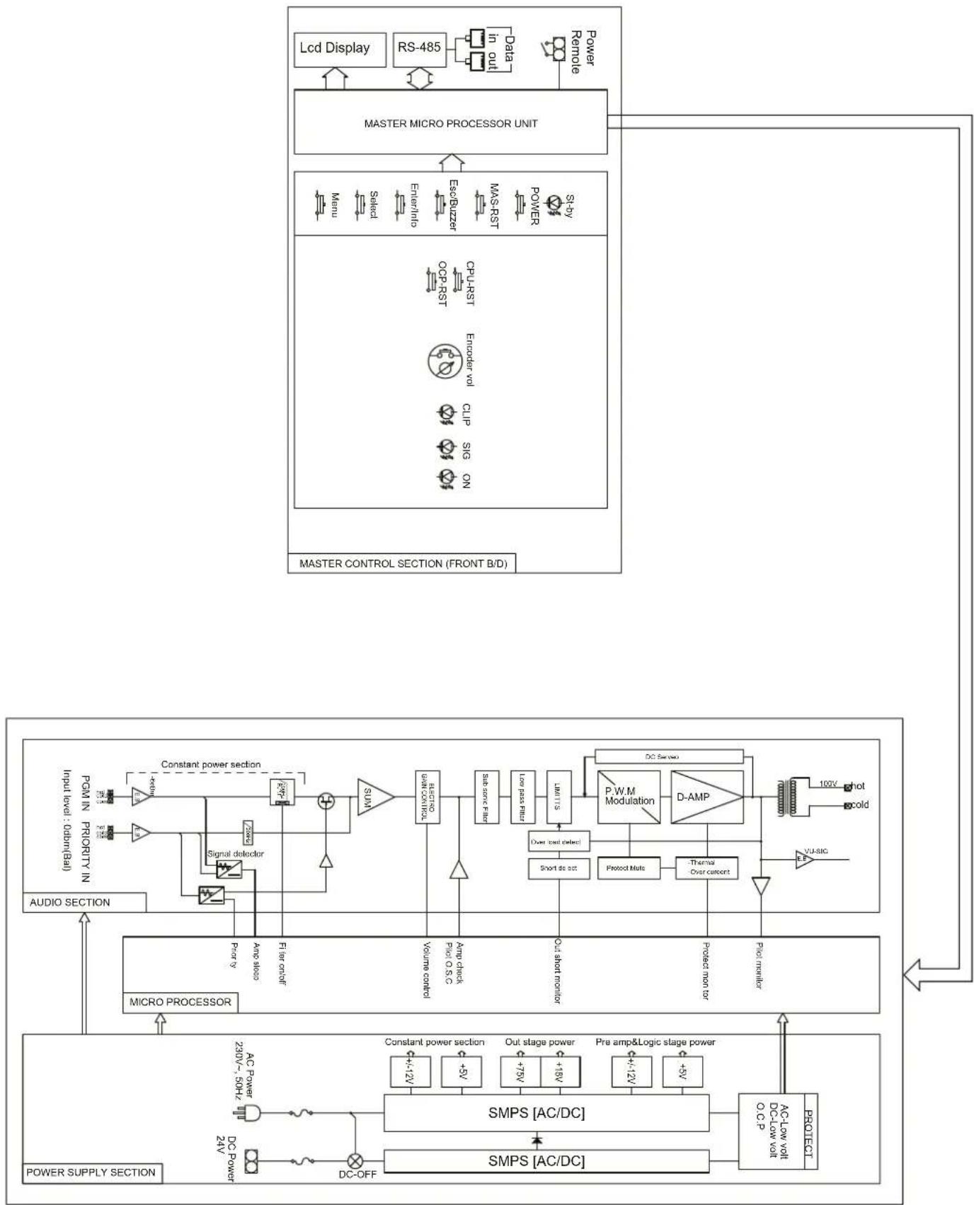
Block diagram see page 29
Output power Rated power: .250W Music power: .350W
THD: <0.5%
Speaker output: 100 V, min. load impedance: 40Ω
Inputs: 1.2V,30kΩ, bal.
Frequency range: .50-18000Hz, ±3dB
S/N ratio: >100dB (A weighted)
High-pass filter: 200Hz, 6dB/oct.
Power supply
Mains operation: .230V/50Hz
Power consumption: .350VA max., 8W standby
Emergency power supply: .24V () Power consumption: .20A max. 280mA standby
Ambient temperature: .0-40°C
Dimensions (W× H× D) .. 482× 88× 410mm,2RS
Weight: 7.5kg
Subject to technical modification.
Priority InputPriority Input Be Careful..
AMP SleepingAmp Sleeping Be Careful..
AC Line CheckAC Line Check LOW VOLTAGE
VOLUME STATUS [..] [DC LOW]
Battery Check Battery Check LOW VOLTAGE
VOLUME STATUS [..] [DC LOW]
OVER TEMPOVER TEMP Limited Output
AMP FAULTAMP FAULT Please AMP Check
VOLUME STATUS [..] [Fault]
Priority InputPriority Input Be Careful..
AMP SleepingAMP Be Careful..
Sleeping
VOLUME STATUS [..] [DC LOW]
Battery Check Battery Check LOW VOLTAGE
VOLUME STATUS [..] [DC LOW]
Sin embargo, la linea bajo la linea STATUS做不到another alternative [DC LOW] y [Normal].
6.2.3 Sobrecarga
SKP-LINE SHORTSKP-LINE SHORT Output MUTE
OVER CURRENTOER CURRENT Protection
OVER TEMPOVER TEMP imited Output
AMP FAULTAMP FAULT Please AMP Check
VOLUME STATUS [..] [Fault]
Priority InputPriority Input Be Careful..
Amp SleepingAmp Sleeping Be Careful..
AC Line CheckAC Line Check LOW VOLTAGE
VOLUME STATUS [..] [DC LOW]
Battery Check Battery Check LOW VOLTAGE
VOLUME STATUS [..] [DC LOW]
OUER TEMPOUER TEMP Limited Output
AMP FAULTAMP FAULT Please AMP Check
VOLUME STATUS [..] [Fault]
| Communication Control | RS-485 MODBUS PROTOCOL |
| Baud rate | 9600, 19200 bps |
| Data Frame | 1 Start bit, 8 Data bit, 1 Stop bit |
| Parity | Non Parity |
| Slave No. 지�� | 1 ~ 99 (Device Setting) |
- SYSTEM CONDITION CHECK
| Code | Bytes | Data M | ag.R | W UnitAddress | ss ParamData Type | ||
| System Status Check | |||||||
| 04h | 30000 | Data HI bit 15 ~ bit 8 Reserved Data LOW bit 7 ~ bit 4 Reserved bit 3 Channel 4 bit 2 Channel 3 bit 1 Channel 2 bit 0 Channel 1 (0=Abence, 1=Presence) | 2 | R | unsigned 16 | ||
- SYSTEM SETTING & VOLUME CHECK
| Code | Bytes Data Mag R/W UnitAddress Parameter Data Type | ||||||
| System Status Check | |||||||
| 04h | 30001 | Channel 1Data HBit 15~bit 8ReservedData LOWbit 7~bit 5Reservedbit 4Battery Modebit 3Sleep Modebit 2Mutebit 1Output Limitbit 0Power(0=OFF,1=ON) | 2 | R | unsigned 16 | ||
| 30002 Channel 2 | |||||||
| 30003 | Channel 3 | ||||||
| 30004 | Channel 4 | ||||||
- SYSTEM SETTING CHECK & VOLUME CHECK
| Code | Bytes | R/W UhitAddeDataPorttarget | Data Type | ||||
| System Setting Check | |||||||
| 04h | 30005 | Channel 1Data HBit 15 ~ bit 8 ReservedData LOW0~99 Volume SET | 2 | R | unsigned 16 | ||
| 30006 Channel 2 | |||||||
| 30007 | Channel 3 | ||||||
| 30008 | Channel 4 | ||||||
- SYSTEM SETTING CHECK & VOLUME CHECK
| Code | Bytes Data Mag R/W | UnitAddress Parameter Data Type | ||||
| System Setting Check | ||||||
| 04h 2 | R | Channel 1Data H0~6AMP Check Interval TimeTime Step0=0.5Hour1=1Hour2=1.5Hour3=3Hour4=6Hour5=12Hour6=12Hour7=22Data LOWbit 7~ bit 4Reservedbit 3Sleep Mode(0=OFF, 1=ON)bit 2AMP Check(0=OFF, 1=ON)bit 1HPF(0=OFF, 1=ON)bit 0Battery(0=NON, 1=YES) | ||||
| 30010 Channel 2 | ||||||
| 30011 | Channel 3 | |||||
| 30012 | Channel 4 | |||||
- VU METER & FAULT STATUS CHECK
| Code | Bytes Data Mag R/W | UnitAddress Parameter | Data Type | ||||
| Fault Monitoring | |||||||
| 04h 2 | R | Channel 1 Data HI 0 ~ 99, 100 VU METER (0~99= Normal, 100= Clipping) Data LOW bit 7 Reserved 16300000 | Reserved AMP Check Error Over Load. Mute Over Temp. Mute Over Temp. Limit Battery Low Volt. AC Low Volt Over current (0= Normal, 1=Fault) | ||||
| 30014 Ch | Channel 2 | ||||||
| 30015 | Channel 3 | ||||||
| 30016 | Channel 4 | ||||||
- SYSTEM PRESET
| Code | Bytes Data Mag R/W UnitAddress Parameter Data Type | ||||||
| System Preset | |||||||
| 10h | 40000 | Data HIReservedData LOW (Power ON/OFF Control)bit 7~bit 1 Reservedbit 0 Power ON/OFF (0=OFF,1=ON) | 2 | W | unsigned 16 | ||
- SYSTEM PRESET
| Code | Bytes Data Mag R/W UnitAddress Parameter Data Type | ||||||
| System Preset | |||||||
| 10h 2 | W | Channel 1Data HBit 15- bit 8 ReservedData LOW (Volume Setup)unsigned 1640QLe me Control | |||||
| 40002 Channel 2 | |||||||
| 40003 | Channel 3 | ||||||
| 40004 | Channel 4 | ||||||
| Code | Bytes | R/W UnitAddress | eBaltBavenger | Data Type | ||
| System Preset | ||||||
| 10h 2 | W | Channel 1 Data HI (AMP Check Time Setup) 0 ~ 6 Time Step 0 = 0.5 Hour 1 = 1 Hour 2 = 1.5 Hour 3 = 3 Hour 4 = 6 Hour 5 = 12 Hour 6 = 24 Hour | Reserved | |||
| unsigned 1640085 bit 7~bit 4 Reserved bit 3 Sleep Mode (0=OFF, 1=ON) bit 2 AMP Check (0=OFF, 1=ON) bit 1 HPF (0=OFF, 1=ON) bit 0 Battery (0=NON, 1=YES) | ||||||
| 40006 Channel 2 | ||||||
| 40007 | Channel 3 | |||||
| 40008 | Channel 4 | |||||
- CRC & Data Flow
| CRC | |||||||
| Slave Address | Function | Starting Addr. Hi | Starting Addr. Lo | No. of Point Hi | No. of Point Lo | CRC LO | CRC HI |
| SUM CRC | |||||||
Data Flow
1) MONITORING
| Query Read (MASTER) | |||||||
| Slave Address | Function | Starting Addr. Hi | Starting Addr. Lo | No. of Point Hi | No. of Point Lo | CRC | CRC |
| 10 | 04 | 00 | 00 | 00 | 02 | XX | XX |
Reading 2 points data from 30000 addresses by Function 04h on digital amp 16.
| Response Read (DIGITAL AMP) | ||||||||
| Slave Address | Function | Byte Count | Byte 3 | Byte 2 | Byte 1 | Byte 0 | CRC | CRC |
| 10 | 04 | 04 | 00 | 00 | 00 | 00 | XX | XX |
Response 2 points data(4Byte) from 30000 addresses by Function 04h on digital amp 16
2) PRESETTING
| Query Preset (MASTER) | |||||||||
| Slave Address | Function | Coil Addr. Hi | Coil Addr. Lo | No. of Reg. Hi | No. of Reg. Lo | Data Hi | Data Lo | CRC | CRC |
| 10 | 10 | 00 | 00 | 00 | 01 | 00 | 00 | XX | XX |
Writing 1 points data(2Byte) from 40000 addresses by Function 10h on digital amp 16
| Response Preset (DIGITAL AMP) | |||||||
| Slave Address | Function | Starting Addr. Hi | Starting Addr. Lo | No. of Point Hi | No. of Point Lo | CRC | CRC |
| 10 | 10 | 00 | 00 | 00 | 01 | XX | XX |
Response 1 points data by Function 10h on digital amp 16
Response interval time: >300msec , Frame interval time: >300msec .
MESSAGE SEQUENCE & INTERVAL
| MASTER | Interval time > 300m sec | DIGITAL AMP |
| Response |
Block Diagram