VS001G - Vacuum Cleaner MAKITA - Free user manual and instructions
Find the device manual for free VS001G MAKITA in PDF.

User questions about VS001G MAKITA
0 question about this device. Answer the ones you know or ask your own.
Ask a new question about this device
Download the instructions for your Vacuum Cleaner in PDF format for free! Find your manual VS001G - MAKITA and take your electronic device back in hand. On this page are published all the documents necessary for the use of your device. VS001G by MAKITA.
USER MANUAL VS001G MAKITA
| EN | Cordless Vacuum Sweeper INSTRUCTION MANUAL 12 | |
| FR | Balayeuse sans fil MANUEL D’INSTRUCTIONS 24 | |
| DE | Akku-Kehrsaugmaschine BETRIEBSANLEITUNG 38 | |
| IT | Spazzatrice aspirante a batteria | ISTRUZIONI PER L’USO 52 |
| NL | Accuveegmachine GEBRUIKSAANWIJZING 66 | |
| ES | Barredora Aspiradora Inalámbrica | MANUAL DE INSTRUCCIONES 80 |
| PT | Varredeira a Bateria MANUAL DE INSTRUÇÕES 94 | |
| EL | Φορητή σκούπα αναρρόφησης | ΕΓΧΕΙΡΙΔΙΟ ΟΔΗΓΙΩΝ 108 |
| TR | Akülü Süpürme Aracı KULLANMA KILAVUZU 123 | |
VS001G
natural_image
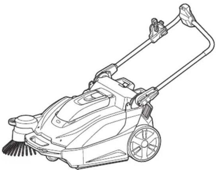
Line drawing of a lawn mower with adjustable handle and brush (no text or symbols)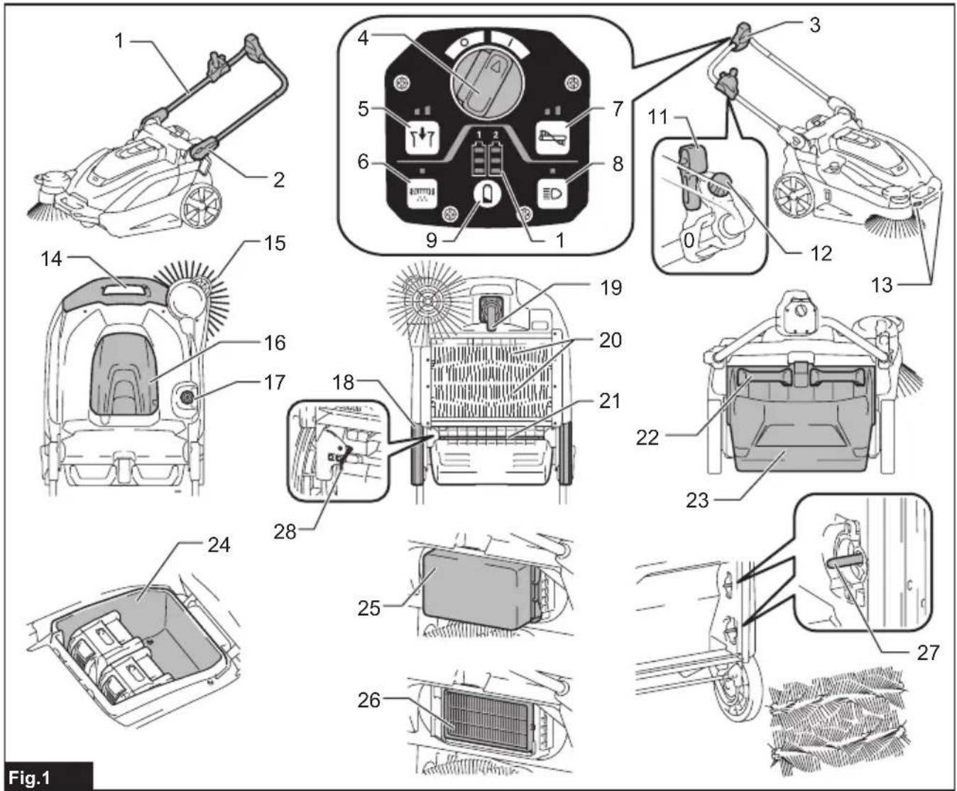
text_image
1 2 3 4 5 6 7 8 9 10 11 12 13 14 15 16 17 18 19 20 21 22 23 24 25 26 27 Fig.1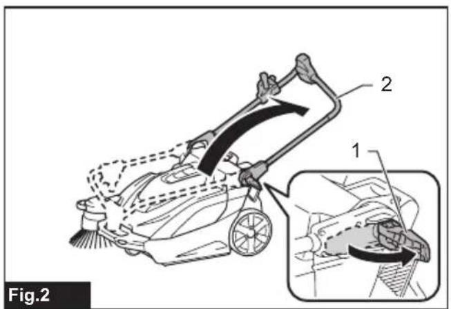
text_image
Fig.2 1 2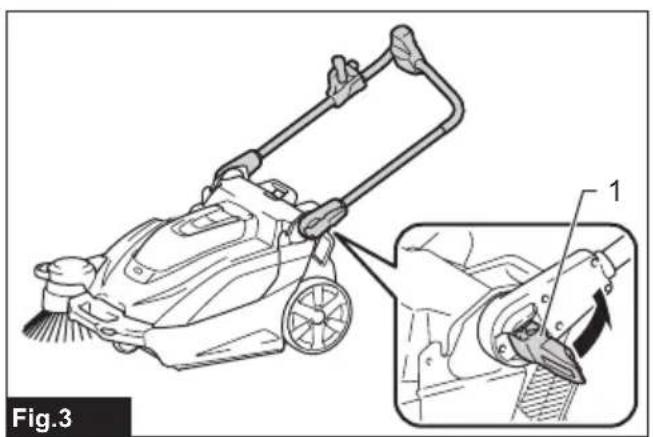
natural_image
Line drawing of a cleaning or cleaning machine with a magnified inset showing the tool path (no text or symbols present)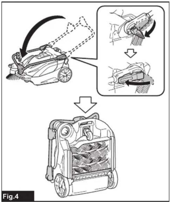
text_image
Fig.4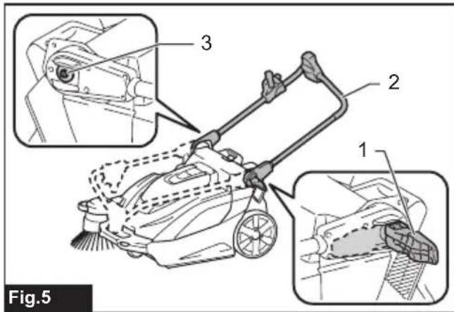
text_image
Fig.5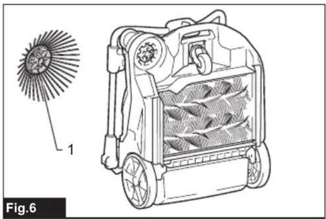
natural_image
Technical line drawing of a mechanical device with internal components and a magnified inset showing a circular component (no text or symbols)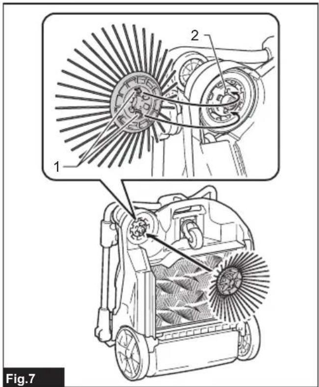
text_image
1 2 Fig.7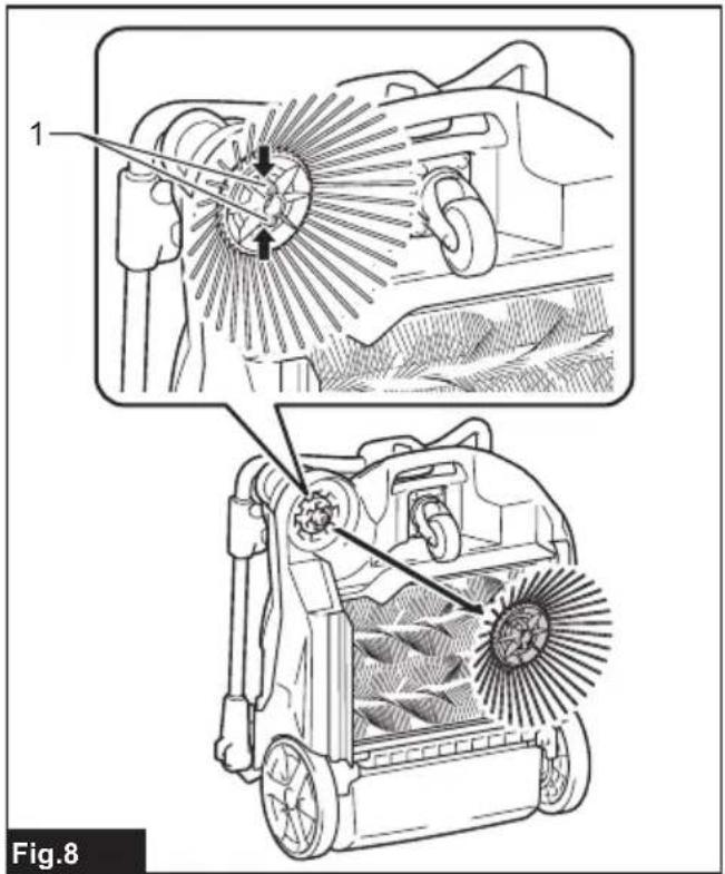
text_image
1 Fig.8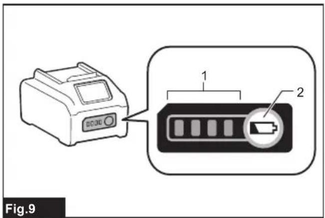
text_image
Fig.9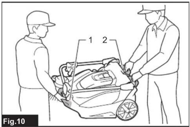
text_image
1 2 Fig.10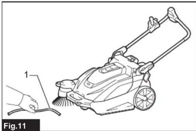
natural_image
Line drawing of a lawn mower with a hand cleaning the blade (no text or symbols)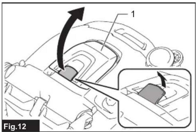
text_image
Fig.12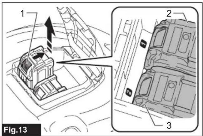
text_image
1 2 3 Fig.13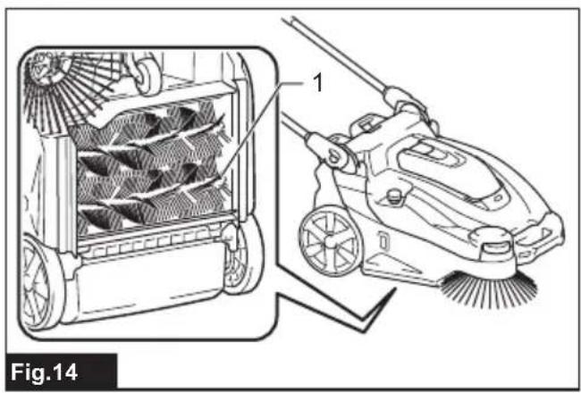
natural_image
Technical illustration of a cleaning or cleaning device with labeled components, showing internal fan structure and brush (no text or symbols)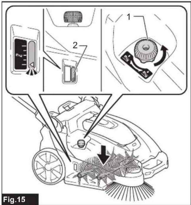
text_image
Fig.15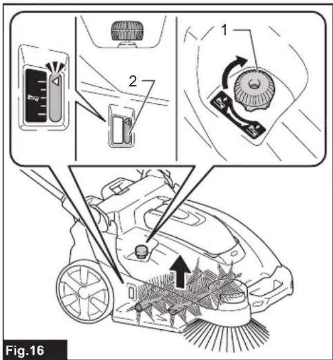
text_image
Fig.16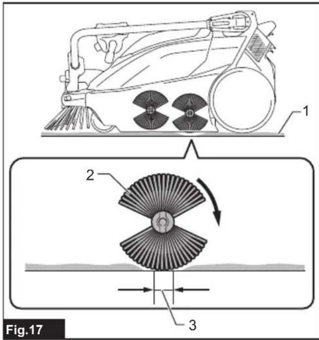
text_image
Fig.17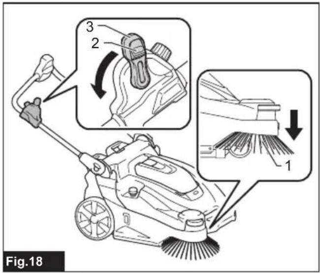
text_image
Fig.18 1 2 3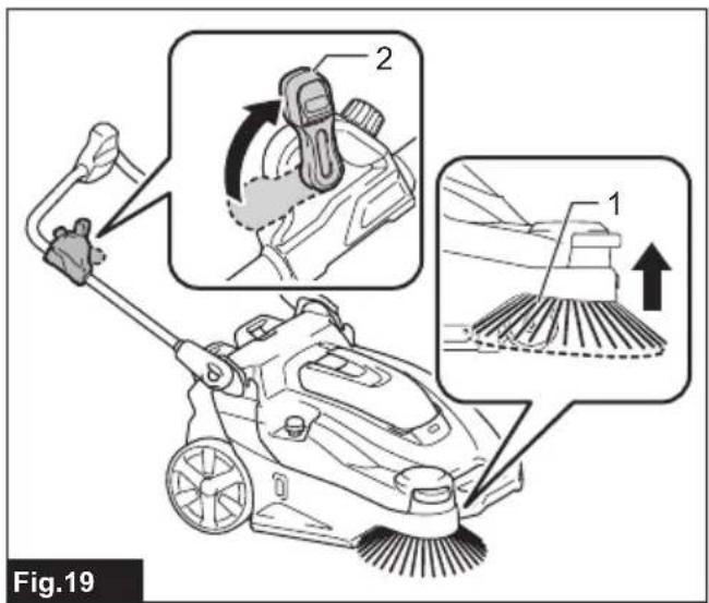
text_image
Fig.19 1 2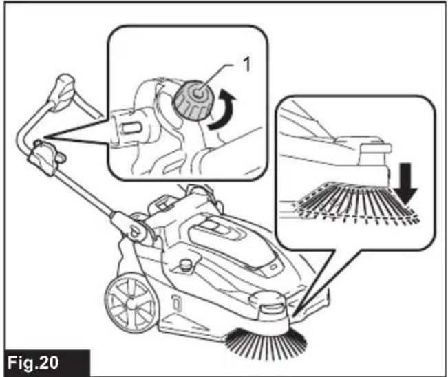
text_image
Fig.20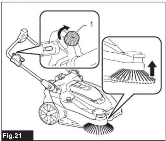
text_image
Fig.21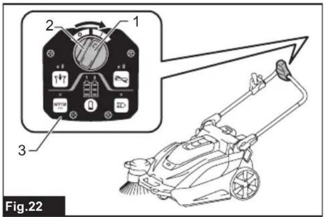
text_image
1 2 3 Fig.22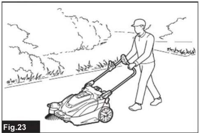
natural_image
Line drawing of a person using a lawn mower in a rural setting (no text or symbols)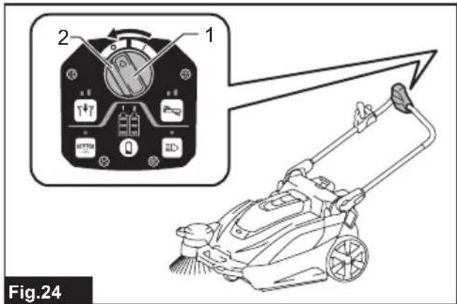
text_image
2 1 Fig.24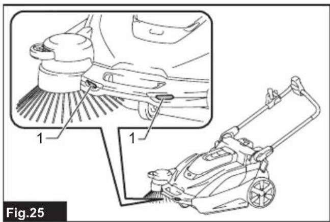
text_image
1 1 Fig.25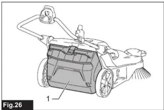
natural_image
Technical line drawing of a lawn mower with labeled components (no text or symbols beyond label)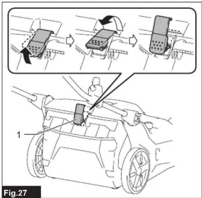
text_image
Fig.27 1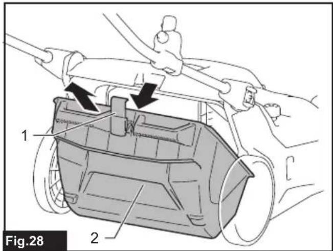
text_image
Fig.28 1 2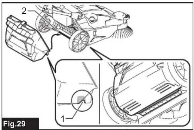
text_image
2 1 Fig.29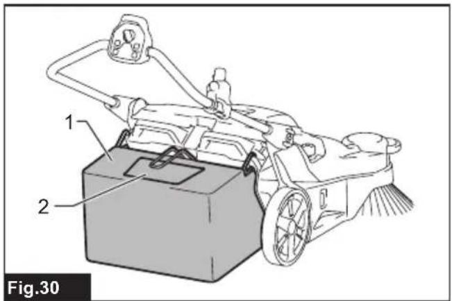
text_image
1 2 Fig.30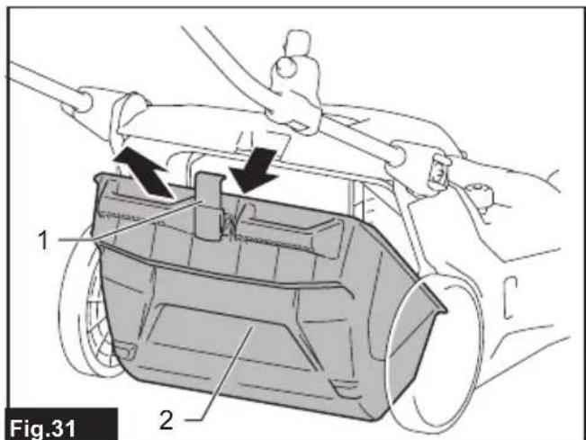
text_image
1 2 Fig.31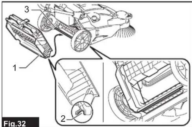
text_image
Fig.32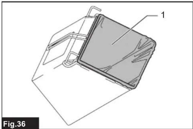
natural_image
Technical line drawing of a mechanical component with labeled part '1', no readable text or symbols present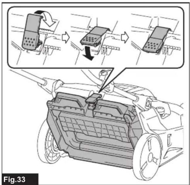
text_image
Fig.33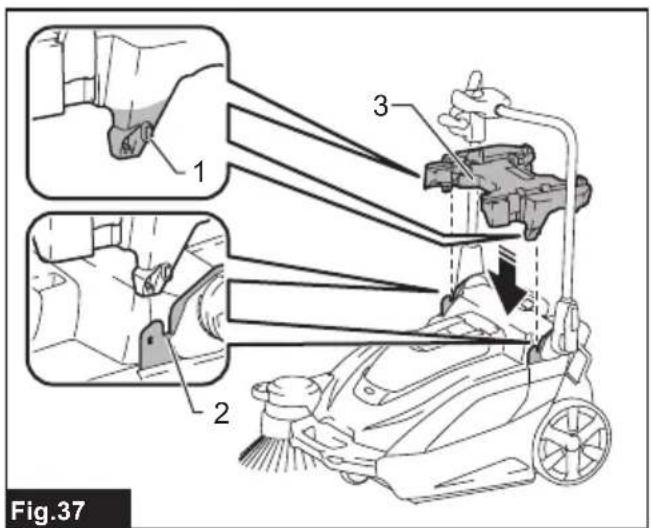
text_image
Fig.37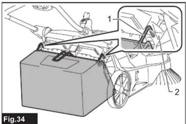
text_image
1 2 Fig.34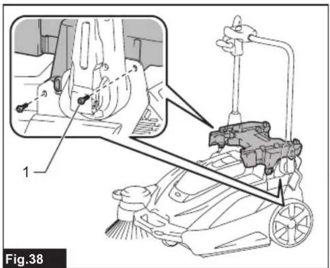
text_image
1 Fig.38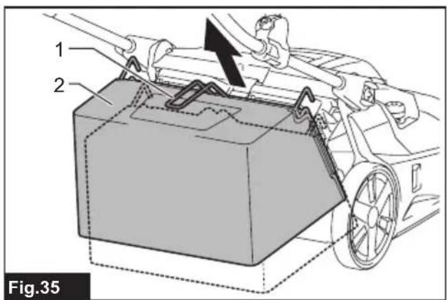
text_image
1 2 Fig.35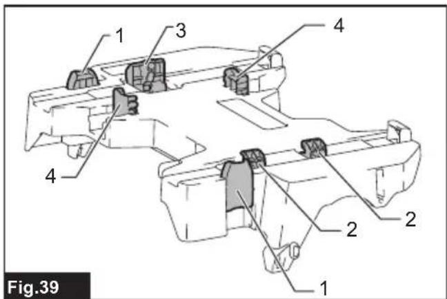
text_image
Fig.39 1 2 3 4 1 2 3 4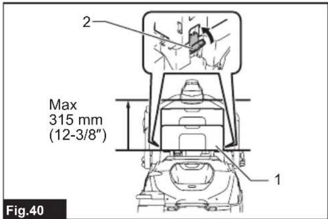
text_image
2 Max 315 mm (12-3/8") 1 Fig.40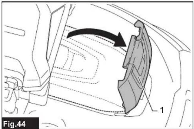
text_image
Fig.44 1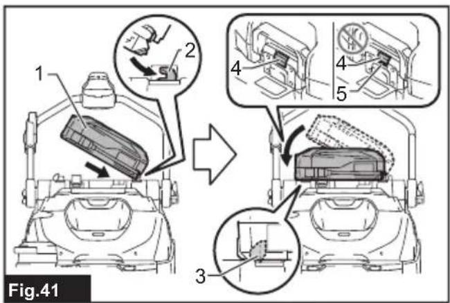
text_image
Fig.41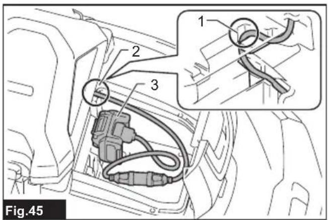
text_image
Fig.45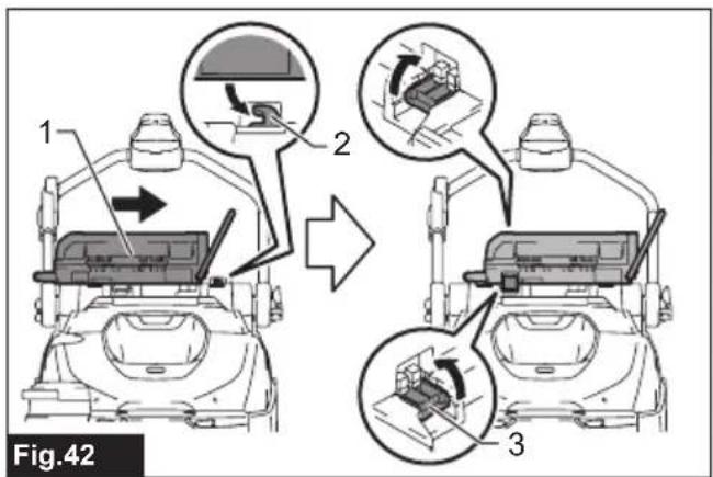
text_image
1 2 3 Fig.42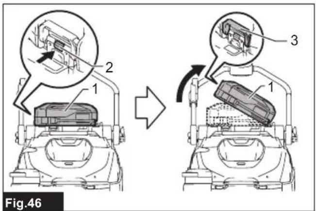
text_image
Fig.46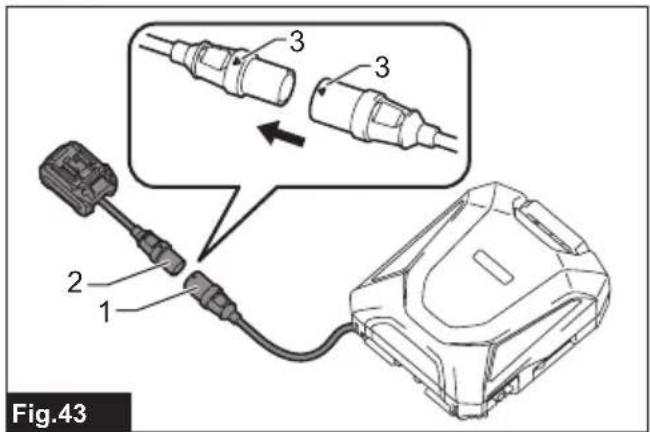
text_image
Fig.43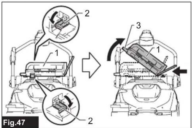
text_image
Fig.47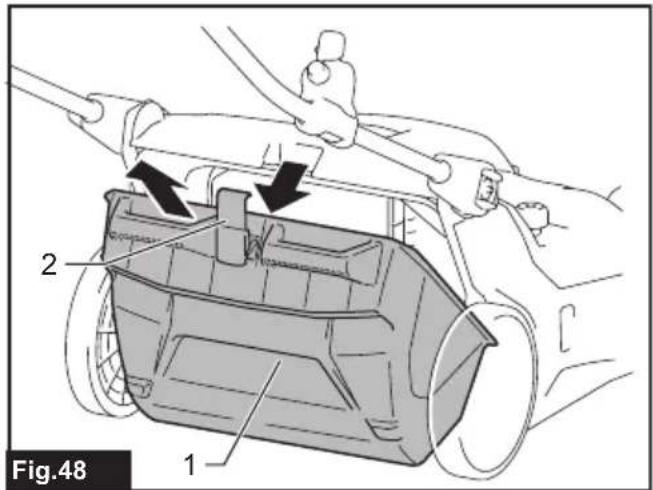
text_image
Fig.48 1 2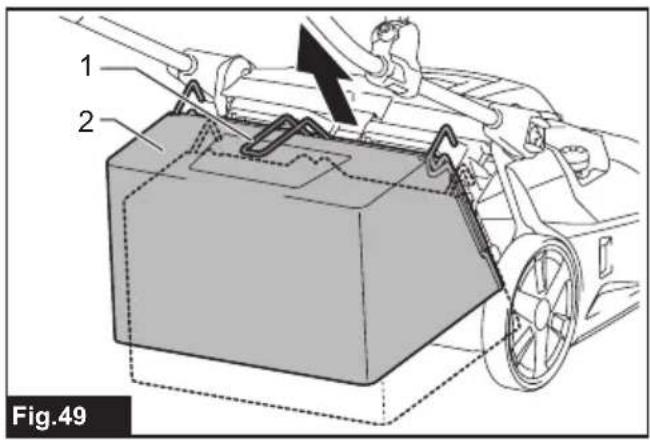
text_image
1 2 Fig.49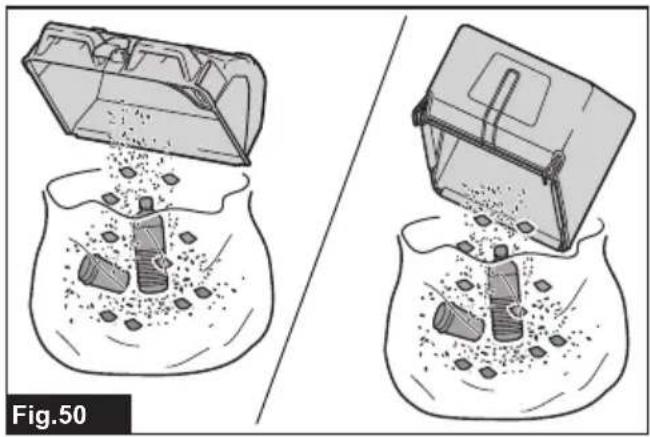
natural_image
Illustration of two fishbowl with plastic debris and a container, showing internal disposal or storage (no text or symbols)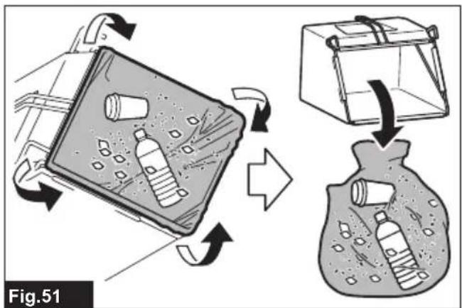
text_image
Fig.51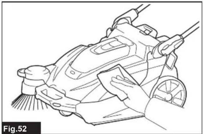
natural_image
Line drawing of a hand cleaning a cleaning machine with a cloth (no text or symbols)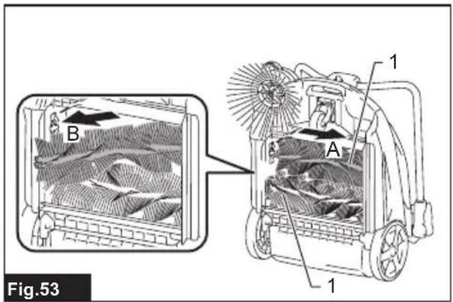
text_image
B A 1 1 Fig.53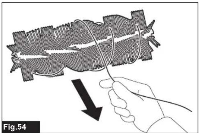
natural_image
Illustration of a hand holding a wire with a black arrow pointing to a biological structure, labeled Fig.54 (no text or symbols on the diagram itself)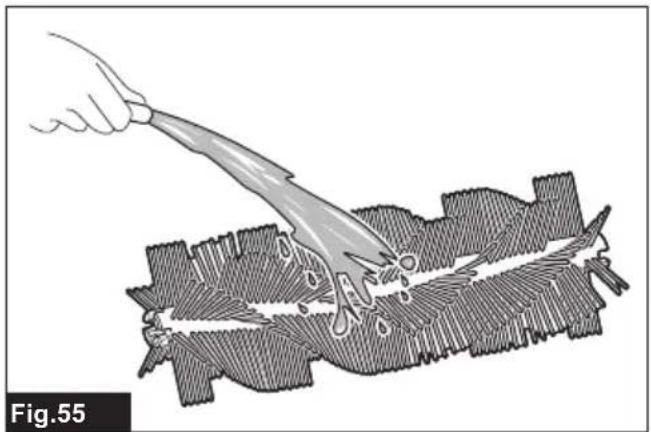
natural_image
Illustration of a hand using a tool to cut a textured surface, labeled Fig.55 (no text or symbols on the diagram itself)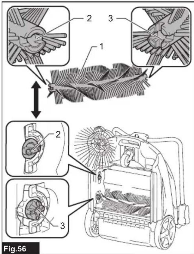
text_image
Fig.56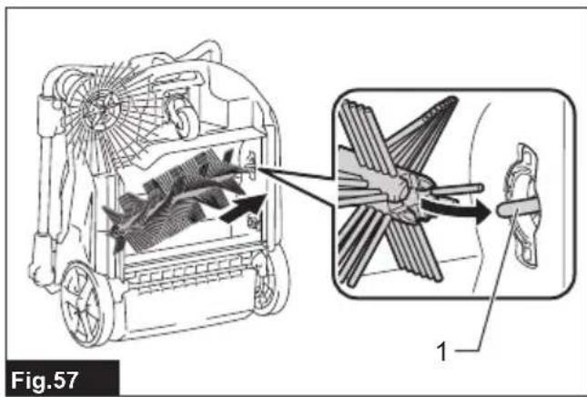
text_image
Fig.57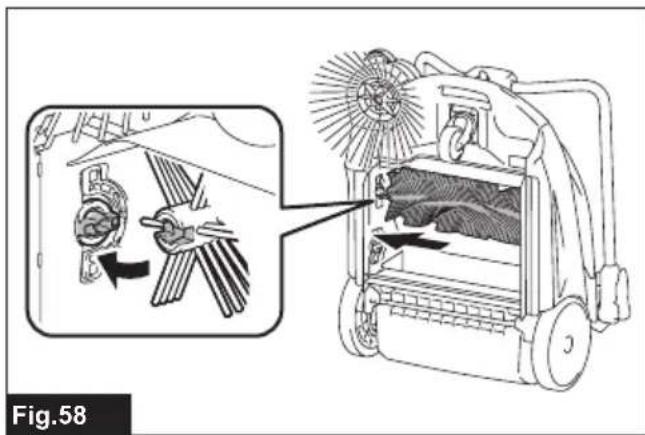
text_image
Fig.58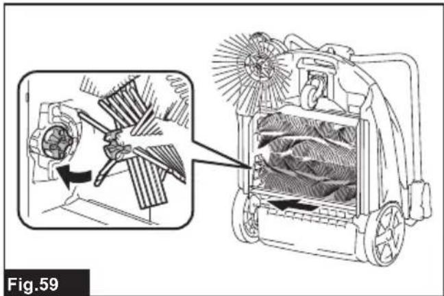
natural_image
Technical illustration of a mechanical device with internal blades and fan components, showing internal structure and assembly (no text or symbols)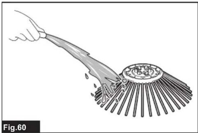
natural_image
Illustration of a hand using a tool to clean or brush the surface of a circular object (no text or symbols)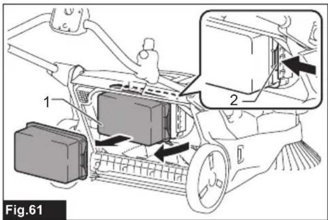
text_image
Fig.61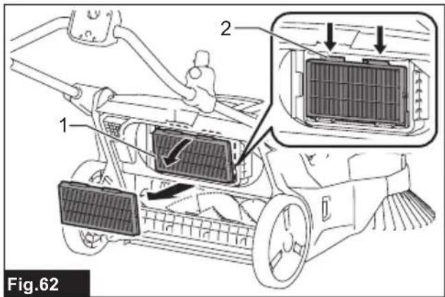
text_image
Fig.62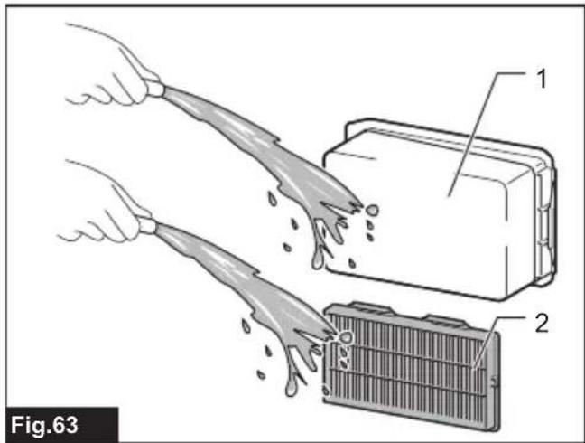
text_image
Fig.63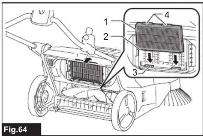
text_image
Fig.64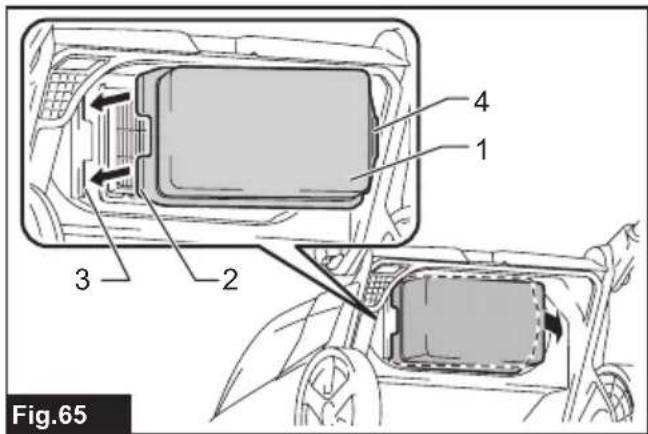
text_image
Fig.65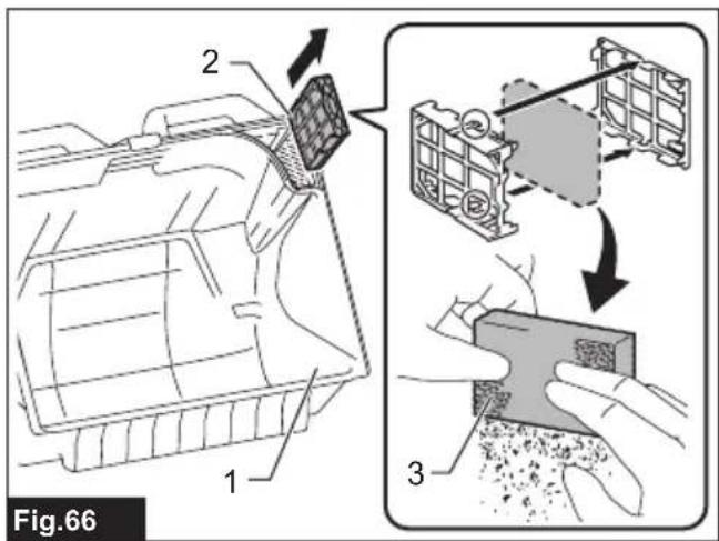
text_image
Fig.66 1 2 3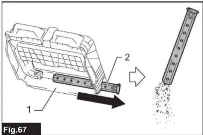
text_image
1 2 Fig.67WARNING
- This appliance is not intended for use by persons (including children) with reduced physical, sensory or mental capabilities, or lack of experience and knowledge.
- For users in Europe:
Children shall not play with the appliance. Cleaning and user maintenance shall not be made by children without supervision. - For users in areas other than Europe:
Children should be supervised to ensure that they do not play with the appliance. - CAUTION: Before carrying out any maintenance operation, disconnect the appliance from the power supply. Perform maintenance on the appliance periodically.
- Rechargeable batteries must be removed from the device before charging.
• To remove or install the battery, first open the battery cover then slide the cartridge out of the tool while pressing the button on the front of the cartridge. - Exhausted batteries must be removed from the device and disposed of safely. Follow local regulations regarding battery disposal.
- If the device is to be stored unused for a long period, the batteries should be removed.
- The power terminals must not be short-circuited.
INTRODUCTION
Specifications
| Model: VS001G | ||
| Waste container capacity 15.6 L | ||
| Cleaning capability *1 Side brush | not used 1,920 m | ^2/h |
| Side brush used 2,600 m | ^2/h | |
| Cleaning width Side brush not used | 480 mm | |
| Side brush used 650 mm | ||
| Rated voltage D.C. 36 V - 40 V max | ||
| Dimensions(L x W x H) | Handle vertical 830 mm x 677 mm x 1,146 mm | |
| Handle folded 830 mm x 677 mm x 467 mm | ||
| Allowable overall weight (GVW) max. 44.0 kg | ||
| Net weight (transportation weight) (with BL4025 x1) | 29.9 kg | |
| Protection degree | IPX4 | |
*1 Assuming a walking speed of 4 km/h.
- Due to our continuing program of research and development, the specifications herein are subject to change without notice.
- Specifications and battery cartridge may differ from country to country.
Applicable battery cartridge and charger
| Battery cartridge | BL4020 / BL4025 / BL4040 / BL4040F / BL4050F / BL4080F |
| Charger | DC40RA / DC40RB / DC40RC / DC40WA |
- Some of the battery cartridges and chargers listed above may not be available depending on your region of residence.
WARNING: Only use the battery cartridges and chargers listed above. Use of any other battery cartridges and chargers may cause injury and/or fire.
Recommended cord connected power source
Portable power pack PDC01 / PDC1200 / PDC1500
- The cord connected power source(s) listed above may not be available depending on your region of residence.
- Before using the cord connected power source, read instruction and cautionary markings on them.
Symbols
The followings show the symbols which may be used for the equipment. Be sure that you understand their meaning before use.

Read instruction manual.

Take particular care and attention.
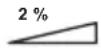
Do not use on a slope of more than 2%.

Do not step onto the appliance.
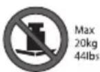
Do not place objects weighing 20 kg (44 lbs) or more on top of the appliance.
To prevent accidents or injury, make sure to switch the appliance off and remove the batteries before maintaining the brushes or performing repairs.

A representative battery applicable to this appliance.

Only for EU countries
Due to the presence of hazardous components in the equipment, waste electrical and electronic equipment, accumulators and batteries may have a negative impact on the environment and human health. Do not dispose of electrical and electronic appliances or batteries with household waste! In accordance with the European Directive on waste electrical and electronic equipment and on accumulators and batteries and waste accumulators and batteries, as well as their adaptation to national law, waste electrical equipment, batteries and accumulators should be stored separately and delivered to a separate collection point for municipal waste, operating in accordance with the regulations on environmental protection. This is indicated by the symbol of the crossed-out wheeled bin placed on the equipment.

Guaranteed sound power level according to EU Outdoor Noise Directive.

Sound power level according to Australia NSW Noise Control Regulation.
Intended use
The appliance is intended for collecting dry debris. The appliance is suitable for commercial use, for example in hotels, schools, hospitals, factories, shops, offices and rental businesses.
Declarations of Conformity
For European countries only
The Declarations of conformity are included in Annex A to this instruction manual.
Safety precautions
Cordless vacuum sweeper safety warnings
- Operators shall be adequately instructed on the use of the vacuum sweeper.
- This vacuum sweeper is for dry use only.
- When not in use, always store the vacuum sweeper indoors.
- Do not use for cleaning purposes on surfaces having a gradient exceeding that marked on the appliance.
- Do not let children play with rechargeable appliance.
- When store the appliance, place the appliance on a flat and stable surface. Store the appliance out of the reach of children.
- Always place the appliance on a flat surface when the appliance will be stood on its end.
- Keep the work location neat and tidy. Also, make sure it is well lit and always kept clean. Failure to do so may cause accidents.
-
Wear appropriate work attire.
-
Do not use battery adapter.
-
Do not touch the battery area with wet hands. Otherwise, electric shock may result.
-
Do not use the filter in a wet. Motor burnout or a breakdown may result.
-
Do not use the appliance when it is raining or when the road surface is wet. Also, do not pick up refuse containing liquid or foam. Motor burnout or a breakdown may result.
-
Do not collect string-like refuse such as cord, string, or wire. These refuse may get entangled in the brushes. Remove the refuse before cleaning operation. Otherwise a breakdown may result.
-
Do not disconnect the earthing line.
-
Do not attempt to clean the exterior or interior with benzine, thinner or cleaning chemicals. Cracks and discoloration may be caused.
-
Wear appropriate protective equipment such as goggles and a dust mask when cleaning dusty location, performing maintenance or disposing of refuse.
-
Mount filters properly. Using the appliance with no filter attached, attached in the wrong position, or in a damaged state could cause motor burnout or a breakdown.
-
Do not disassemble the appliance. Doing so may cause a breakdown.
- If you notice anything that seems abnormal, halt the appliance and remove the batteries immediately.
- Before using the appliance, check to make sure there are no damaged parts and that each part is operating correctly. If there is a damaged part, have it replaced or repaired, as appropriate, by an authorized dealer unless specifically indicated otherwise in the instruction manual.
- There is a risk of being squeezed, caught or injured by the drive belt, main brushes, side brush, handle or rear wheel.
- Do not use the appliance to collect toxic substances such as asbestos.
- Do not use the side brush when cleaning contaminated or dusty location.
- Do not use the appliance in a location where hazardous materials or open flame are present. Doing so may cause a fire or explosion.
- Do not use the appliance in an explosive and flammable location.
Battery tool use and care
- Recharge only with the charger specified by the manufacturer. A charger that is suitable for one type of battery pack may create a risk of fire when used with another battery pack.
- Use power tools only with specifically designated battery packs. Use of any other battery packs may create a risk of injury and fire.
- When battery pack is not in use, keep it away from other metal objects, like paper clips, coins, keys, nails, screws or other small metal objects, that can make a connection from one terminal to another. Shorting the battery terminals together may cause burns or a fire.
- Under abusive conditions, liquid may be ejected from the battery; avoid contact. If contact accidentally occurs, flush with water. If liquid contacts eyes, additionally seek medical help. Liquid ejected from the battery may cause irritation or burns.
- Do not use a battery pack or tool that is damaged or modified. Damaged or modified batteries may exhibit unpredictable behaviour resulting in fire, explosion or risk of injury.
- Do not expose a battery pack or tool to fire or excessive temperature. Exposure to fire or temperature above 130 °C may cause explosion.
- Follow all charging instructions and do not charge the battery pack or tool outside the temperature range specified in the instructions. Charging improperly or at temperatures outside the specified range may damage the battery and increase the risk of fire.
Important safety instructions for battery cartridge
-
Before using battery cartridge, read all instructions and cautionary markings on (1) battery charger, (2) battery, and (3) product using battery.
-
Do not disassemble or tamper with the battery cartridge. It may result in a fire, excessive heat, or explosion.
- If operating time has become excessively shorter, stop operating immediately. It may result in a risk of overheating, possible burns and even an explosion.
-
If electrolyte gets into your eyes, rinse them out with clear water and seek medical attention right away. It may result in loss of your eyesight.
-
Do not short the battery cartridge:
(1) Do not touch the terminals with any conductive material.
(2) Avoid storing battery cartridge in a container with other metal objects such as nails, coins, etc.
(3) Do not expose battery cartridge to water or rain.
A battery short can cause a large current flow, overheating, possible burns and even a breakdown.
-
Do not store and use the tool and battery cartridge in locations where the temperature may reach or exceed 50 °C (122 °F).
-
Do not incinerate the battery cartridge even if it is severely damaged or is completely worn out. The battery cartridge can explode in a fire.
-
Do not nail, cut, crush, throw, drop the battery cartridge, or hit against a hard object to the battery cartridge. Such conduct may result in a fire, excessive heat, or explosion.
-
Do not use a damaged battery.
-
The contained lithium-ion batteries are subject to the Dangerous Goods Legislation requirements.
For commercial transports e.g. by third parties, forwarding agents, special requirement on packaging and labeling must be observed. For preparation of the item being shipped, consulting an expert for hazardous material is required. Please also observe possibly more detailed national regulations.
Tape or mask off open contacts and pack up the battery in such a manner that it cannot move around in the packaging.
-
When disposing the battery cartridge, remove it from the tool and dispose of it in a safe place. Follow your local regulations relating to disposal of battery.
-
Use the batteries only with the products specified by Makita. Installing the batteries to non-compliant products may result in a fire, excessive heat, explosion, or leak of electrolyte.
-
If the tool is not used for a long period of time, the battery must be removed from the tool.
-
During and after use, the battery cartridge may take on heat which can cause burns or low temperature burns. Pay attention to the handling of hot battery cartridges.
-
Do not touch the terminal of the tool immediately after use as it may get hot enough to cause burns.
-
Do not allow chips, dust, or soil stuck into the terminals, holes, and grooves of the battery cartridge. It may cause heating, catching fire, burst and malfunction of the tool or battery cartridge, resulting in burns or personal injury.
- Unless the tool supports the use near high-voltage electrical power lines, do not use the battery cartridge near high-voltage electrical power lines. It may result in a malfunction or breakdown of the tool or battery cartridge.
- Keep the battery away from children.
SAVE THESE INSTRUCTIONS.
⚠️CAUTION: Only use genuine Makita batteries. Use of non-genuine Makita batteries, or batteries that have been altered, may result in the battery bursting causing fires, personal injury and damage. It will also void the Makita warranty for the Makita tool and charger.
Tips for maintaining maximum battery life
- Charge the battery cartridge before completely discharged. Always stop tool operation and charge the battery cartridge when you notice less tool power.
- Never recharge a fully charged battery cartridge. Overcharging shortens the battery service life.
- Charge the battery cartridge with room temperature at 10 °C - 40 °C ( 50 °F - 104 °F ). Let a hot battery cartridge cool down before charging it.
- When not using the battery cartridge, remove it from the tool or the charger.
- Charge the battery cartridge if you do not use it for a long period (more than six months).
Noise
The typical A-weighted noise level determined according to EN60335-2-72:
Sound pressure level ( L_pA ): 70 dB(A) or less
Uncertainty (K): 3 dB (A)
The noise level under working may exceed 80 dB (A).
NOTE: The declared noise emission value(s) has been measured in accordance with a standard test method and may be used for comparing one tool with another.
NOTE: The declared noise emission value(s) may also be used in a preliminary assessment of exposure.
WARNING: Wear ear protection.
WARNING: The noise emission during actual use of the power tool can differ from the declared value(s) depending on the ways in which the tool is used especially what kind of workpiece is processed.
⚠ WARNING: Be sure to identify safety measures to protect the operator that are based on an estimation of exposure in the actual conditions of use (taking account of all parts of the operating cycle such as the times when the tool is switched off and when it is running idle in addition to the trigger time).
Vibration
The vibration total value (tri-axial vector sum) determined according to EN60335-2-72:
Vibration emission ( a_h ): 2.5 m/s ^2 or less
Uncertainty (K) : 1.5 m/s ^2
NOTE: The declared vibration total value(s) has been measured in accordance with a standard test method and may be used for comparing one tool with another.
NOTE: The declared vibration total value(s) may also be used in a preliminary assessment of exposure.
WARNING: The vibration emission during actual use of the power tool can differ from the declared value(s) depending on the ways in which the tool is used especially what kind of workpiece is processed.
WARNING: Be sure to identify safety measures to protect the operator that are based on an estimation of exposure in the actual conditions of use (taking account of all parts of the operating cycle such as the times when the tool is switched off and when it is running idle in addition to the trigger time).
Names of parts
▶ Fig.1
| 1 | Handle | 2 | Handle lock lever | 3 | Control panel | 4 | ON/OFF switch |
| 5 | Suction button | 6 | Filter shake button | 7 | Main brush button | 8 | Lamp button |
| 9 | Check button | 10 | Indicator lamps | 11 | Side brush ON/OFF lever | 12 | Side brush height adjusting knob |
| 13 | Lamp | 14 | Grip | 15 | Side brush | 16 | Battery box cover |
| 17 | Main brush height adjusting knob | 18 | Rear wheel | 19 | Front wheel | 20 | Main brushes |
| 21 | Waste container shaft | 22 | Grip (waste container part) | 23 | Waste container | 24 | Battery box |
| 25 | Prefilter | 26 | HEPA filter | 27 | Brush shaft | 28 | Earthing line |
Introduction of separately sold items
⚠️CAUTION: These accessories or attachments are recommended for use with your Makita tool specified in this manual. The use of any other accessories or attachments might present a risk of injury to persons. Only use accessory or attachment for its stated purpose.
For details of separately sold items, refer to the catalog or contact the dealer or our sales office.
- Multifunction adapter
- Dust bag
- Makita genuine battery and charger
NOTE: Some items in the list may be included in the tool package as standard accessories. They may differ from country to country.
PREPARATIONS FOR USE
Assembly
⚠️CAUTION: Before operating the appliance, make sure the ON/OFF switch is turned off and the batteries have been removed.
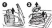
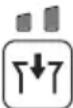
Handle angle adjustment
You can adjust the angle of the handle to make it easier to operate the appliance. At the factory shipment, the handle is folded down.
⚠️CAUTION: Properly engage the handle lock lever. If the handle collapses or falls over, there is a danger of injury.
- Release the lock of the handle lock lever.
- Adjust the handle to the desired angle.
▶ Fig.2: 1. Handle lock lever 2. Handle
- Engage the handle lock lever.
▶ Fig.3: 1. Handle lock lever
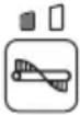
Folding down the handle
When you stand the appliance on its end for storage/inspection or when you transport the appliance by lifting the appliance, fold down the handle.
▶ Fig.4
If the handle is loose and rattles
If the handle is loose and rattles even though the handle lock lever is properly locked, adjust it by tightening the nut opposite the handle lock lever. If the appliance is used when the handle is loose and rattles, there is a danger of collapse or fall over of the handle, possibly causing injury.
▶ Fig.5: 1. Handle lock lever 2. Handle 3. Tightening nut (for adjusting looseness)
Attaching and removing the side brush
The side brush can be used to extend the cleaning width and also used to clean the areas along walls.
⚠️ CAUTION: Attach the side brush correctly. If the brush comes loose, it may contact with persons, possibly causing injury.
Attachment
- Extend the side brush and stand the appliance on its end as shown in the figure.
▶ Fig.6: 1. Side brush - Align the hooks (2 locations) of the side brush with the mounting holes and attach the side brush.
The hooks (2 locations) of the side brush can be aligned with any of the 6 holes.
▶ Fig.7: 1. Hooks (2 locations) 2. Holes (6 locations)
NOTE: To make it easier to engage the hooks and holes, rotate the side brush counterclockwise while the side brush lever is lowered.
Removal
While pinching inward on the grips of the hooks, remove the side brush.
▶ Fig.8: 1. Grips of hooks
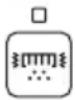
Charging the batteries
Indicating the remaining battery capacity
Press the check button on the battery cartridge to indicate the remaining battery capacity. The indicator lamps light up for a few seconds.
▶ Fig.9: 1. Indicator lamps 2. Check button
| Indicator lamps Remaining | capacity | ||
| Lighted Off | Blinking | ||
| 75% to 100% | |||
| 50% to 75% | |||
| 25% to 50% | |||
| 0% to 25% | |||
| Charge the battery. | |||
| The battery may have malfunctioned. | |||
NOTE: Depending on the conditions of use and the ambient temperature, the indication may differ slightly from the actual capacity.
NOTE: The first (far left) indicator lamp will blink when the battery protection system works.
Remaining battery capacity indication (control panel)
You can also check the remaining battery capacity on the control panel. The remaining battery capacity is displayed when the ON/OFF switch is turned on or off, or when the check button is pressed. The battery indicator lamps light up for 3 seconds.
| Indicator lamps Remaining | battery capacity | ||
| On | [A446]Off | Blinking | |
 | 50% to 100% | ||
| [A2X5] | 20% to 50% | ||
 | 0% to 20% | ||
| [YYXD] | Charge the battery | ||
Things to know before use
Transporting the appliance
⚠️CAUTION: Before transporting the appliance, make sure the ON/OFF switch is turned off and the batteries have been removed.
⚠️CAUTION: Empty the waste container and make sure that the waste container is properly locked by the hook before lifting and transporting the appliance. Failure to lock the hook could result in injury.
⚠️CAUTION: Lifting and transporting the appliance should always be performed by at least two persons using a safe carrying posture. Transporting the appliance in an unsafe manner could result in injury.
⚠️CAUTION: When loading and unloading the appliance in slope, be careful not to let the wheels fall off.
Two persons should transport the appliance, one holding the grip and the other holding the grip (waste container part).
▶ Fig.10: 1. Grip 2. Grip (waste container part)
Work environment
If there is string-like refuse such as cords or wire in the location to be cleaned, clear it away before proceeding. The string-like refuse may become tangled in the main brushes and the side brush.
▶ Fig.11: 1. String-like refuse
Protection function
This appliance is equipped with a protection function. When one of the following conditions occurs, the protection function automatically stops all motors. The lamps on the control panel indicates the error state.
| Illumination state Error | state Action | |||
| On | Off | Blinking | ||
 | Battery error C | Charge the batteries. | ||
 | Appliance temperature is high | Allow the appli-ance to cool down. | ||
 | Brush overload | Stop use of the brush and remove the source of the overload. | ||
 | Suction overload | Stop use of the suction mode and remove the source of the overload. | ||
 | Filter shake overload | Stop use of the filter shake func-tion and remove the source of the overload. | ||
 | Restart prevention | Switch off the ON/OFF switch. | ||
Restart prevention
This appliance is equipped with a restart prevention function. If the batteries are inserted while the ON/OFF switch is turned on, or if the appliance recovers from low-power mode* while the ON/OFF switch is turned on, the restart prevention function prevents an unexpected restart. When the ON/OFF switch is turned off, the error indication disappears. When the ON/OFF switch is turned on afterwards, the appliance starts.
* Low-power mode: When all of the following conditions apply, the appliance turns low-power mode to save the battery capacity.
— No motors operate.
— The front lamps are off.
— No button has been pressed for one minute.
This mode cuts off power to some electronic circuits.
NOTE: To cancel an error indication other than restart prevention, turn off the ON/OFF switch and perform one of the following three actions.
— Turn on the ON/OFF switch.
— Press a button on the control panel.
— Perform no operation for one minute.
NOTE: Regardless of whether or not an error has occurred, you can turn on or off the lamps.
NOTE: If no operation is performed for one minute after an error has occurred while the ON/OFF switch is on, all control panel indications turn off, but the error has not been cleared.
— If the lamps are on: Press any button on the control panel to redisplay the error indication.
— If the lamps are off: The appliance is in low-power mode, so pressing a button on the control panel triggers the restart prevention.
Protections against other causes
Protection system is also designed for other causes that could damage the appliance and allows the appliance to stop automatically. Take all the following steps to clear the causes, when the appliance has been brought to a temporary halt or stop in operation.
- Turn the appliance off, and then turn it on again to restart.
- Charge the battery(ies) or replace it/them with recharged battery(ies).
- Let the appliance and battery(ies) cool down.
If no improvement can be found by restoring protection system, then contact your local Makita Service Center.
USAGE
Mounting/removing the batteries
⚠️CAUTION: Make sure the ON/OFF switch is turned off before mounting or removing the batteries.
⚠CAUTION: Be careful not to get your fingers caught when opening and closing the battery box cover. There is a danger of injury.
Mounting the batteries
Open the battery box cover. Align the battery with the groove, and insert it until it clicks into place. Close the battery box cover.
▶ Fig.12: 1. Battery box cover
Removing the batteries
While holding down the button on the battery, lift the battery out of the battery box.
▶ Fig.13: 1. Button 2. Battery "1" 3. Battery "2"
The appliance will operate with either one or two batteries mounted.
- Mounting two batteries
With two batteries mounted side by side, battery "1" is used first. When battery "1" is exhausted, the appliance automatically switches to battery "2" without a pause in operation.
NOTE: Even if battery "1" is mounted, when battery "2" is being used, the appliance does not switch to battery "1" unless battery "2" is exhausted or the ON/OFF switch is turned off.
- Mounting one battery
The mounted battery is detected automatically.
Operating the appliance
Main brush height adjustment
The height of the main brush (rear side only) at the bottom of the appliance is adjustable. Adjust appropriately depending on the condition of the floor to be cleaned, the length of the main brush, etc.
▶ Fig.14: 1. Main brush (rear side)
Turn the main brush height adjusting knob to adjust the height of the main brush.
Turn the knob in the direction indicated by the arrow to reduce the height of the main brush (to adjust towards more contact with the floor).
▶ Fig.15: 1. Main brush height adjusting knob 2. Main brush height
Turn the knob in the direction indicated by the arrow to increase the height of the main brush (to adjust towards less contact with the floor).
▶ Fig.16: 1. Main brush height adjusting knob 2. Main brush height
NOTE: The main brushes become worn down. Check and adjust the height of the main brushes regularly. If it is not possible to adjust the brushes sufficiently, replace them.
How to check the appropriate main brush height
NOTICE: Observe the appropriate height. Too much pressure on the main brush accelerates the wear of the main brush and shorten run-time.
A main brush track width indicates the appropriate height of the main brush.
-
Raise up the front of the appliance by holding the grip or handle. Move the appliance to a flat surface covered with the following materials, and then gently lower the appliance onto the surface.
-
Layer of dust
- Layer of chalk
- Turn on the ON/OFF switch and rotate the main brushes approx. 15 - 30 seconds.
- Turn off the ON/OFF switch. Raise the front of the appliance to prevent the main brush from contacting the surface and move the appliance to another area.
Check that the main brush track is evenly rectangular, 25 - 40 mm (1" - 1-9/16") wide.
Readjust the height by using the main brush height adjusting knob if the track shape is inappropriate.
▶ Fig.17: 1. Layer of dust or chalk 2. Main brush (rear side) 3. Track
Turning the side brush on or off
The side brush can be used to extend the cleaning width and also used to clean the areas along walls.
To use the side brush, hold down the lock off button and lower the side brush ON/OFF lever.
The side brush is lowered to the floor surface. When the side brush is on, it rotates in conjunction with the main brushes.
▶ Fig.18: 1. Side brush 2. Lock off button 3. Side brush ON/OFF lever
Raise the side brush ON/OFF lever when the side brush is not in use.
The side brush is raised from the floor surface. When the side brush is off, it does not rotate.
▶ Fig.19: 1. Side brush 2. Side brush ON/OFF lever
Side brush height adjustment
When the side brush is on, the height is adjustable. Adjust appropriately depending on the condition of the floor to be cleaned, the length of the side brush, etc.
Turn the side brush height adjusting knob to adjust the height of the side brush.
Turn the knob in the direction indicated by the arrow to reduce the height of the side brush (to adjust towards more contact with the floor).
▶ Fig.20: 1. Side brush height adjusting knob
Turn the knob in the direction indicated by the arrow to increase the height of the side brush (to adjust towards less contact with the floor).
▶ Fig.21: 1. Side brush height adjusting knob
NOTE: The side brush becomes worn down. Check and adjust the height of the side brush regularly. If it is not possible to adjust the brush sufficiently, replace it.
Starting cleaning
⚠️CAUTION: Hold the appliance firmly during use. Also, do not leave the appliance unattended regardless of whether the appliance is on a slope or not. The appliance may move and cause an accident.
⚠️CAUTION: Do not rotate the brushes or start the filter shake function when the waste container or dust bag are not attached to the appliance.
⚠️CAUTION: Do not touch rotating brushes. There is a danger of injury.
CAUTION: Do not use the appliance to collect items that could become tangled in the brushes, such as cords, string, or wire. Doing so may cause a breakdown. Clear away string-like refuse beforehand.
CAUTION: Do not use the appliance in unstable places such as locations where the floor has a steep slope or is very slippery. There is a danger that operation could be unstable or the appliance could tip over.
⚠️CAUTION: Wear protective equipment such as a mask, glasses and gloves when cleaning in a dusty environment.
Cleaning
NOTICE: Do not turn the ON/OFF switch forcibly without pressing the lock off button.
- Turn the ON/OFF switch with pressing the lock off button to the "I" position to turn on power.
▶ Fig.22: 1. ON/OFF switch 2. Lock off button 3. Control panel - If necessary, change settings by pressing the function switches on the control panel. (Refer to "Control panel operations.")
- Push the handle to start cleaning.
▶ Fig.23
NOTE: For how to turn the side brush on or off, refer to "Turning the side brush on or off."
- Turn the ON/OFF switch with pressing the lock off button to the "O" position to turn off power.
▶ Fig.24: 1. ON/OFF switch 2. Lock off button
Control panel operations
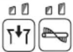
Changing the main brush rotation speed
When power is turned on, each press of the [main brush button] switches the brush rotation speed mode.
| Button/LED indication | Mode Function | |
 | Standard mode | The brush rotation speed is standard. This is optimal for when there is a lot of dirt. |
 | Quiet mode | This is optimal for when you want to clean quietly or when you want to clean for a long time. |
NOTE: The rotation speed of the side brush is linked to the rotation speed of the main brushes.
NOTE: When power is turned on, operation starts in the mode being used when power was previously turned off.
Changing the suction mode
When power is turned on, each press of the [suction button] switches the suction power mode.
| Button/LED indication | Mode Function | |
 | Standard mode | The suction power is standard. This is optimal for cleaning in a dusty environment. |
 | Quiet mode | This is optimal for quiet and long cleaning. |
 | Off | This is optimal for when suction is not needed, as well as quieter and longer cleaning than quiet mode. |
NOTE: When power is turned on, operation starts in the mode being used when power was previously turned off.
NOTE: If the filter shake function is turned on while the suction fan is in use, the suction fan stops temporarily and then restarts when filter shake stops.
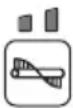
Turns the filter shake function on or off
Pressing the [filter shake button] toggles the filter shake function between on and off.
| Button/LED indication | Mode Function | |
 | On | Turns on the filter shake function.When the filter shake function is operating, dust is removed from the filter automatically to eliminating the clogging. It turns off automatically after about 15 seconds. |
 | Off | Turns off the filter shake function. |
Turns the lamps on or off
Pressing the [lamp button] toggles the lamps between on and off.
| Button/LED indication | Mode Function | |
 | On | Turns the lamps on. |
 | Off | Turns the lamps off. |
▶ Fig.25: 1. Lamp
Lamp auto-off function
The lamps turn off automatically if the following two conditions continue for 30 minutes.
- None of the motors (main brushes, suction, and filter shake) is operating.
- No button has been pressed.
Showing the remaining battery capacity
Press the [check button] to display the remaining battery capacity.
Using the waste container
▶ Fig.26: 1. Waste container
- The refuse is collecting in the waste container.
- For details of the cleaning procedure, refer to "Starting cleaning."
Removal
- Raise the hook of the waste container.
- Remove the hook from the appliance.
▶ Fig.27: 1. Hook
- Remove the waste container from the appliance.
▶ Fig.28: 1. Hook 2. Waste container
Attachment
- Attach the groove of the waste container to the waste container shaft of the appliance.
▶ Fig.29: 1. Groove 2. Waste container shaft - Fit the hook onto the appliance and lower the hook to secure the waste container in place.
Using the dust bag
Optional accessory
▶ Fig.30: 1. Dust bag 2. Transparent window
- The dust bag has a large capacity, making it suitable for collecting bulky refuse such as fallen leaves.
- You can check how much refuse has been collected by looking through the transparent window on the top.
- Use the waste container when suction dust. The dust bag is not as airtight as the waste container.
- For details of the cleaning procedure, refer to "Starting cleaning."
NOTE: When collecting light refuse such as fallen leaves, using suction mode is recommended. Using suction mode helps to collect more refuse than when the mode is off.
Attachment
- Remove the waste container from the appliance.
▶ Fig.31: 1. Hook 2. Waste container - Attach the groove of the dust bag frame to the waste container shaft of the appliance.
▶ Fig.32: 1. Dust bag frame 2. Groove 3. Waste container shaft - Fit the hook onto the appliance and lower the hook to secure the dust bag frame in place.
▶ Fig.33 - Attach the dust bag by hanging the hooks on the left and right of the dust bag on the attaching grooves.
▶ Fig.34: 1. Hook 2. Groove
Removal
Reverse the steps of the attachment procedure.
Attaching a polyethylene bag
NOTICE: When attaching a polyethylene bag, it may be difficult to see inside of the dust bag.
Attaching a polyethylene bag to the dust bag gives you the convenience when it is time to discard refuse, because discarding work can be completed by simply removing and throwing away the polyethylene bag with its contents.
- Lift up the grip (for the dust bag) and remove the dust bag.
▶ Fig.35: 1. Grip (for the dust bag) 2. Dust bag - Attach a polyethylene bag (commercial appliance, bag opening perimeter is over 1,600 mm (63")) to the dust bag.
▶ Fig.36: 1. Polyethylene bag - Attach the dust bag by hanging the hooks on the left and right of the dust bag on the attaching grooves.
Using a multifunction adapter
Optional accessory
Attaching a multifunction adapter makes it possible to mount a Makpac or portable power pack.
⚠️CAUTION: Properly secure the multifunction adapter in place using the supplied screws.
⚠️CAUTION: Properly secure the Makpac or portable power pack in place by using the latches or hooks on the multifunction adapter.
⚠️CAUTION: Do not place objects weighting more than 20 kg (44 lbs) or more on the multifunction adapter.
CAUTION: Do not use the handle of a Makpac or portable power pack mounted on the multifunction adapter to transport or operate the appliance. Doing so may cause accidents.
⚠️CAUTION: Do not stand the appliance on its end when a Makpac or portable power pack is mounted on the multifunction adapter. Doing so may damage the locking mechanism of the multifunction adapter, and the Makpac or portable power pack may fall off.
Attaching the multifunction adapter
- Align the protrusions on the left and right of the multifunction adapter with the mounting grooves on the appliance and attach the multifunction adapter.
▶ Fig.37: 1. Protrusion 2. Groove 3. Multifunction adapter
If it is difficult to mount the multifunction adapter, loosen the handle lock lever on the appliance. When loosen the handle lock lever, fold down the handle to prevent the handle from falling over, and then mount the multifunction adapter.
- Tighten the four screws to secure the multifunction adapter in place.
▶ Fig.38: 1. Screws
Removing the multifunction adapter
Reverse the steps of the attachment procedure.
Names of parts of multifunction adapter
▶ Fig.39: 1. Securing latch (for Makpac) 2. Hooks A (for PDC01 / PDC1200 / PDC1500) 3. Hook B (for PDC1200 / PDC1500) 4. Hooks C (for PDC01)
Mounting a Makpac
⚠CAUTION: Do not exceed the height 315 mm (12-3/8") when mounting the Makpac.
Firmly fit the two securing latches on the left and right into the mounting notches of the Makpac to secure the Makpac in place.
▶ Fig.40: 1. Makpac 2. Securing latches
Removing a Makpac
Disengage the two securing latches on the left and right and remove the Makpac.
Mounting a portable power pack
CAUTION: Do not use the appliance with the portable power pack on your back.
CAUTION: When mounting a portable power pack on the multifunction adapter, make sure the cord of the portable power pack is arranged properly. Otherwise sagging cord may be scraped by the floor and disconnection, smoke, or fire result.
- Fit the bottom edge of the portable power pack onto hooks A and secure it in place with hook B or hook C. Confirm that the portable power pack does not detach from the appliance by lifting up the handle of the portable power pack lightly.
• PDC1200 / PDC1500
Fit the bottom edge of the portable power pack onto hooks A and secure it in place with hook B. Confirm that the portable power pack does not detach from the appliance by lifting up the handle of the portable power pack lightly.
If the red indicator of the lock button is visible, the portable power pack is not completely locked.
▶ Fig.41: 1. Portable power pack 2. Hooks A 3. Hook B 4. Lock button 5. Red indicator
• PDC01
Fit the bottom edge of the portable power pack onto hooks A and secure it in place with hooks C. Hook B is not used.
▶ Fig.42: 1. Portable power pack 2. Hooks A 3. Hooks C
- Align the triangle marks on the socket of the portable power pack and the plug of the adapter (for the XGT battery) and fit them together firmly as far as they will go.
▶ Fig.43: 1. Socket of portable power pack 2. Plug of adapter (for XGT battery) 3. Triangle marks
- Open the battery box cover.
▶ Fig.44: 1. Battery box cover
- As shown in the figure, arrange the cord so it passes through the groove in the multifunction adapter and the battery box. Align the adapter (for the XGT battery) with the groove in the battery insertion opening, and insert the adapter until it clicks into place.
▶ Fig.45: 1. Groove in multifunction adapter
2. Groove in battery box 3. Adapter (for XGT battery)
- Close the battery box cover.
Removing a portable power pack PDC1200 / PDC1500
- Remove the plug of the adapter (for the XGT battery) from the socket of the portable power pack and remove the cord.
NOTICE: Do not pull the cord when removing from the plug of adapter. Also, do not carry the portable power pack by holding only the cord.
The cord may break or otherwise be damaged.
- While holding down the lock button of the portable power pack, raise the handle of the portable power pack.
▶ Fig.46: 1. Portable power pack 2. Lock button 3. Handle
PDC01
- Remove the plug of the adapter (for the XGT battery) from the socket of the portable power pack and remove the cord.
NOTICE: Do not pull the cord when removing from the plug of adapter. Also, do not carry the portable power pack by holding only the cord.
The cord may break or otherwise be damaged.
- Disengage hooks C and pull the portable power pack out and then up.
▶ Fig.47: 1. Portable power pack 2. Hooks C 3. Handle
Handling after use
⚠️CAUTION: If the appliance will not be in use, make sure the ON/OFF switch is turned off and the batteries have been removed.
Discarding refuse
⚠️CAUTION: Always wear protective equipment such as a mask and gloves when disposing of refuse. There is a danger you may touch sharp objects in the refuse, possibly causing injury.
⚠️CAUTION: Discard refuse early, before too much accumulates. The suction power could be reduced.
- Remove the hook and then remove the waste container from the appliance.
▶ Fig.48: 1. Waste container 2. Hook
When using the dust bag, raise the grip and lift out the dust bag.
▶ Fig.49: 1. Grip (for dust bag) 2. Dust bag
- Transport the waste container or dust bag to the refuse collection are and discard the refuse.
▶ Fig.50
When using the dust bag, attaching a polyethylene bag inside allows you to discard the polyethylene bag together with the refuse.
▶ Fig.51
- After discarding refuse, mount the waste container or dust bag to the appliance. Make sure that the hook is properly locked.
MAINTENANCE
⚠️CAUTION: Always be sure that the appliance is switched off and the battery cartridge is removed before attempting to perform inspection or maintenance.
NOTICE: Never use gasoline, benzine, thinner, alcohol or the like. Discoloration, deformation or cracks may result.
Maintenance
Cleaning the appliance body
⚠️ CAUTION: Do not wash the appliance body with water. Doing so may cause a breakdown.
To remove dirt from the appliance body, wipe it using a cloth that has been moistened with a small amount of diluted neutral detergent.
▶ Fig.52
Cleaning the main brushes
- Fold down the handle and stand the appliance on its end as shown in the figure.
- Push in a main brush in the direction indicated by the arrow A in the figure.
Remove one end of the main brush in the direction indicated by the arrow B in the figure.
▶ Fig.53: 1. Main brush
- Remove the other end of the main brush from the brush shaft.
- In like manner, remove the other main brush.
- If there is string-like refuse adhered to the brushes, remove it by hand.
▶ Fig.54
- Shake off dust, and wash the brushes with water if they are very dirty. After washing, leave them to dry in the shade; do not use them until they are completely dry.
▶ Fig.55
- Orient each main brush so that the shapes of the ends match the mounting areas of the appliance, as shown in the figure.
If the shapes of the ends do not match, reverse the left-right orientation of the main brush so they match.
▶ Fig.56: 1. Main brush 2. Minus shape 3. Plus shape
- Fit a main brush onto the brush shaft of the appliance in the direction indicated by the arrow in the figure.
▶ Fig.57: 1. Brush shaft - Fit a main brush into mounting area of the appliance, in the direction indicated by the arrow in the figure, and secure it in place.
▶ Fig.58
NOTE: If the shapes of the ends do not match, you will not be able to mount the main brush. In this case, go back to step 7 and redo the process.
- In like manner, mount the other main brush.
▶ Fig.59
CAUTION: After mounting the main brushes, check that the shapes are correctly engaged.
NOTE: If the main brushes are worn down to a shorter length, replace them.
Cleaning the side brush
For the procedure for mounting and removing the side brush, refer to "Attaching and removing the side brush."
-
Remove the side brush.
-
Shake off dust, and wash the brush with water if it is very dirty. After washing, leave the brush to dry in the shade; do not use it until it is completely dry.
▶ Fig.60
- Mount the side brush.
NOTE: If the side brush is worn down to a shorter length, replace it.
Cleaning the filters
⚠️CAUTION: Make sure the filters are mounted properly, and do not use the appliance when the filters are not in place. Also, do not use filters that are damaged or wet. Motor burnout or a breakdown may result.
NOTICE: The filters can be washed and reused. To prevent damage to the filters, do not use the following items when cleaning them.
— Air dusters
— High-pressure washers
— Brushes made of hard materials such as metal
-
Remove the waste container.
-
While pushing on the hook of the prefilter in the direction indicated by the arrow in the figure, remove the prefilter.
▶ Fig.61: 1. Prefilter 2. Hook
- While pushing on the hooks of the HEPA filter in the direction indicated by the arrows in the figure, remove the HEPA filter.
▶ Fig.62: 1. HEPA filter 2. Hook
- Shake off dust, and wash the filters with water if they are very dirty. After washing, leave the prefilter and HEPA filter to dry in the shade; do not use them until they are completely dry.
▶ Fig.63: 1. Prefilter 2. HEPA filter
- To mount the HEPA filter, fit the edge of the HEPA filter onto the grooves on the appliance, and push the filter into place. Check that the hooks are securely fixed.
▶ Fig.64: 1. HEPA filter 2. Edge 3. Groove 4. Hook
- To mount the prefilter, fit the protrusions on the prefilter into the grooves on the appliance, and push the filter into place. Check that the hook is securely fixed.
▶ Fig.65: 1. Prefilter 2. Protrusion 3. Groove 4. Hook
Cleaning the sponge filter
⚠️CAUTION: After cleaning the sponge filter, be sure to install it on the waste container. If washed in water, dry it up before installing.
When the sponge filter is clogged with dust, remove it from the waste container and then wipe it off or wash in water.
-
Remove the sponge case from the waste container.
-
Open the sponge case to remove the sponge filter.
▶ Fig.66: 1. Waste container 2. Sponge case 3. Sponge filter
-
Wipe off the sponge filter or wash in water.
-
Install the sponge filter in its original position.
Cleaning the tube
When using the dust bag (optional accessory), the tube may become clogged with fine refuse such as sand, pebbles, and small fallen leaves.
-
Pull the tube from the dust bag frame.
-
Remove the refuse from the tube.
▶ Fig.67: 1. Dust bag frame 2. Tube
- Install the tube in its original position.
Periodic inspections
To ensure a long service life for the appliance and safety usage, perform the inspections listed below periodically.
Daily inspections
- Waste container: empty the container.
- Filters: if they are dirty, cleaning them.
- Brushes: if string-like refuse get entangled, remove it.
- Control and movable parts: check that they move smoothly.
Weekly inspections
- Main brush height: if the height is inappropriate, readjust it.
- Screws (when using multifunction adapter): if they are loose, tighten them.
Replacement/replenishment of consumable items
Brush replacement
If the main brushes and side brush become worn out, ask your local Makita service center for replacement.
Replacing the main brushes
Replace the main brushes if they cannot be adjusted appropriately. Refer to "Main brush height adjustment." For removing and mounting the main brushes, refer to "Cleaning the main brushes."
Replacing the side brush
Replace the side brush if it does not contact the floor when the side brush height adjusting knob is turned to the lowest position. Refer to "Side brush height adjustment."
For removing and mounting the side brush, refer to "Attaching and removing the side brush."
AVERTISSEMENT
▶ Fig.7: 1. Crochets (2 emplacements) 2. Orifices (6 emplacements)
⚠ WAARSCHUWING: Draag gehoorbescherming.
▶ Fig.11: 1. Langdradig afval
Beveiligingsfunctie
▶ Fig.13: 1. Knop 2. Accu "1" 3. Accu "2"
▶ Fig.53: 1. Escobilla principal
Carregar as baterias
Montar/remover as baterias
Liga ou desliga as lâmpadas
▶ Şek.13: 1. Düğme 2. Batarya "1" 3. Batarya "2"