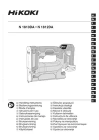
N1810DA - Stapler HiKOKI - Free user manual and instructions
Find the device manual for free N1810DA HiKOKI in PDF.


| Product Type | Cordless Stapler |
| Brand | HiKOKI |
| Model | N1810DA |
| Magazine Capacity | 150 staples |
| Compatible Staples | HiKOKI only, type: crown 0.5 mm, width 9 mm, length 10 mm (N1810DA) |
| Weight | 1.5 kg (with battery BSL1820M) |
| Dimensions (H × W × D) | 166 mm × 85 mm × 235 mm |
| Power Source | 18 V lithium-ion battery (sold separately) |
| Motor Type | DC motor |
| Recommended Battery | BSL1820M (2.0 Ah) or other compatible HiKOKI 18 V batteries |
| Operating Temperature | 0 °C to 40 °C |
| Sound Pressure Level | 67 dB (A) (typical value) |
| Sound Power Level | 78 dB (A) (typical value) |
| Vibration | 1.7 m/s² (typical value, uncertainty K=1.5 m/s²) |
| Main Functions | Fastening of sealing sheets and thermal insulation materials |
| Safety | Trigger lock, push lever, thermal protection, automatic jam stop |
| Maintenance and Cleaning | Clean the magazine and feeding mechanism by blowing daily; wipe the exterior with a soft, dry cloth |
| Spare Parts and Reparability | Repair by HiKOKI authorized center; use only identical replacement parts |
| General Information | Warranty according to national regulations; do not dispose of with household waste (recycling) |
Frequently Asked Questions - N1810DA HiKOKI
User questions about N1810DA HiKOKI
0 question about this device. Answer the ones you know or ask your own.
Ask a new question about this device
Download the instructions for your Stapler in PDF format for free! Find your manual N1810DA - HiKOKI and take your electronic device back in hand. On this page are published all the documents necessary for the use of your device. N1810DA by HiKOKI.
USER MANUAL N1810DA HiKOKI
natural_image
Technical line drawing of a mechanical device with no visible text or symbols
en Handling instructions
de Bedienungsanleitung
fr Mode d'emploi
it Istruzioni per l'uso
nl Gebruiksaanwijzing
es Instrucciones de manejo
pt Instruções de uso
sv Bruksanvisning
da Brugsanvisning
no Bruksanvisning
fi Käyttöohjeet
el Οδηγίες χειρισμού
pl Instrukcja obsługi
hu Kezelési utasítás
cs Návod k obsluze
tr Kullanım talimatları
ro Instructiuni de utilizare
sl Navodila za rokovanje
sk Pokyny na manipuláciu
bg Инструкция за експлоатация
sr Uputstvo za rukovanje
hr Upute za rukovanje
1
2
natural_image
Diagram of a car interior with a directional arrow and a labeled component (no text or symbols present)3
4
5
6
7
8
natural_image
Technical line drawing of a mechanical device with labeled component '6' and directional arrows (no text or symbols beyond label)9
10
natural_image
Line drawing of a hand using a digital camera to adjust the case (no text or symbols present)11
12
13
GENERAL POWER TOOL SAFETY WARNINGS
WARNING
Read all safety warnings and all instructions.
Failure to follow the warnings and instructions may result in electric shock, fire and/or serious injury.
Save all warnings and instructions for future reference.
The term "power tool" in the warnings refers to your mains-operated (corded) power tool or battery-operated (cordless) power tool.
1) Work area safety
a) Keep work area clean and well lit.
Cluttered or dark areas invite accidents.
b) Do not operate power tools in explosive atmospheres, such as in the presence of flammable liquids, gases or dust.
Power tools create sparks which may ignite the dust or fumes.
c) Keep children and bystanders away while operating a power tool.
Distractions can cause you to lose control.
2) Electrical safety
a) Power tool plugs must match the outlet. Never modify the plug in any way. Do not use any adapter plugs with earthed (grounded) power tools.
Unmodified plugs and matching outlets will reduce risk of electric shock.
b) Avoid body contact with earthed or grounded surfaces, such as pipes, radiators, ranges and refrigerators.
There is an increased risk of electric shock if your body is earthed or grounded.
c) Do not expose power tools to rain or wet conditions.
Water entering a power tool will increase the risk of electric shock.
d) Do not abuse the cord. Never use the cord for carrying, pulling or unplugging the power tool. Keep cord away from heat, oil, sharp edges or moving parts.
Damaged or entangled cords increase the risk of electric shock.
e) When operating a power tool outdoors, use an extension cord suitable for outdoor use.
Use of a cord suitable for outdoor use reduces the risk of electric shock.
f) If operating a power tool in a damp location is unavoidable, use a residual current device (RCD) protected supply.
Use of an RCD reduces the risk of electric shock.
3) Personal safety
a) Stay alert, watch what you are doing and use common sense when operating a power tool. Do not use a power tool while you are tired or under the influence of drugs, alcohol or medication.
A moment of inattention while operating power tools may result in serious personal injury.
b) Use personal protective equipment. Always wear eye protection.
Protective equipment such as dust mask, non-skid safety shoes, hard hat, or hearing protection used for appropriate conditions will reduce personal injuries.
c) Prevent unintentional starting. Ensure the switch is in the off position before connecting to power source and/or battery pack, picking up or carrying the tool. Carrying power tools with your finger on the switch or energising power tools that have the switch on invites accidents.
d) Remove any adjusting key or wrench before turning the power tool on.
A wrench or a key left attached to a rotating part of the power tool may result in personal injury.
e) Do not overreach. Keep proper footing and balance at all times.
This enables better control of the power tool in unexpected situations.
f) Dress properly. Do not wear loose clothing or jewellery. Keep your hair, clothing and gloves away from moving parts.
Loose clothes, jewellery or long hair can be caught in moving parts.
g) If devices are provided for the connection of dust extraction and collection facilities, ensure these are connected and properly used.
Use of dust collection can reduce dust-related hazards.
4) Power tool use and care
a) Do not force the power tool. Use the correct power tool for your application.
The correct power tool will do the job better and safer at the rate for which it was designed.
b) Do not use the power tool if the switch does not turn it on and off.
Any power tool that cannot be controlled with the switch is dangerous and must be repaired.
c) Disconnect the plug from the power source and/or the battery pack from the power tool before making any adjustments, changing accessories, or storing power tools.
Such preventive safety measures reduce the risk of starting the power tool accidentally.
d) Store idle power tools out of the reach of children and do not allow persons unfamiliar with the power tool or these instructions to operate the power tool.
Power tools are dangerous in the hands of untrained users.
e) Maintain power tools. Check for misalignment or binding of moving parts, breakage of parts and any other condition that may affect the power tool's operation.
If damaged, have the power tool repaired before use.
Many accidents are caused by poorly maintained power tools.
f) Keep cutting tools sharp and clean. Properly maintained cutting tools with sharp cutting edges are less likely to bind and are easier to control.
g) Use the power tool, accessories and tool bits etc. in accordance with these instructions, taking into account the working conditions and the work to be performed.
Use of the power tool for operations different from those intended could result in a hazardous situation.
5) Battery tool use and care
a) Recharge only with the charger specified by the manufacturer.
A charger that is suitable for one type of battery pack may create a risk of fire when used with another battery pack.
English
b) Use power tools only with specifically designated battery packs.
Use of any other battery packs may create a risk of injury and fire.
c) When battery pack is not in use, keep it away from other metal objects, like paper clips, coins, keys, nails, screws or other small metal objects, that can make a connection from one terminal to another.
Shorting the battery terminals together may cause burns or a fire.
d) Under abusive conditions, liquid may be ejected from the battery; avoid contact. If contact accidentally occurs, flush with water. If liquid contacts eyes, additionally seek medical help.
Liquid ejected from the battery may cause irritation or burns.
6) Service
a) Have your power tool serviced by a qualified repair person using only identical replacement parts.
This will ensure that the safety of the power tool is maintained.
PRECAUTION
Keep children and infirm persons away.
When not in use, tools should be stored out of reach of children and infirm persons.
CORDLESS STAPLER SAFETY WARNINGS
- Always assume that the tool contains fasteners.
Careless handling of the stapler can result in unexpected firing of fasteners and personal injury. - Do not point the tool towards yourself or anyone nearby. Unexpected triggering will discharge the fastener causing an injury.
- Do not actuate the tool unless the tool is placed firmly against the workpiece. If the tool is not in contact with the workpiece, the fastener may be deflected away from your target.
- Disconnect the tool from the power source when the fastener jams in the tool. While removing a jammed fastener, the stapler may be accidentally activated if it is plugged in.
- Use caution while removing a jammed fastener. The mechanism may be under compression and the fastener may be forcefully discharged while attempting to free a jammed condition.
- Do not use this stapler for fastening electric cables.
It is not designed for electric cable installation and may damage the insulation of electric cables thereby causing electric shock or fire hazards.
ADDITIONAL SAFETY WARNINGS
- Safe operation through correct usage.
This tool was designed for driving staples into wood and similar materials. Use it for its intended purpose only.
- Be careful of ignition and explosions.
Since sparks may fly during stapling, it is dangerous to use this tool near lacquer, paint, benzine, thinner, gasoline, gas, adhesives and similar inflammable substances as they may ignite or explode. Under no circumstances should this tool therefore be used in the vicinity of such inflammable material.
- Always wear eye protection (protective goggles).
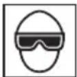
When operating the power tool, always wear eye protection, and ensure that surrounding people wear eye protection too.
The possibility of fragments of staples or staples that were not properly hit entering the eye is a threat to sight. Eye protection can be bought at any hardware store.
Always wear eye protection while operating this tool. Use either eye protection or a wide vision mask over prescription glasses.
Employers should always enforce the use of eye protection equipment.
- Protect your ears and head.
When engaged in stapling work please wear ear mufflers and head protection. Also, depending on condition, ensure that surrounding people also wear ear mufflers and head protection.
- Pay attention to those working close to you.
It would be very dangerous if staples that were not properly driven in should hit other people. Therefore, always pay attention to the safety of the people around you when using this tool. Always make sure that nobody's body, hands or feet are close to the staple outlet.
- Never point the staple outlet towards people.
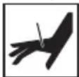
Always assume the tool contains fasteners.
If the staple outlet is pointed towards people, serious accidents may be caused if you mistakenly discharge the tool. When connecting and check disconnecting the battery, during staple loading or similar operations, be sure the staple outlet is not pointed towards anyone (including yourself). Even when no staples are loaded at all, it is dangerous to discharge the tool while pointing it at someone, so never attempt to do so. No horseplay. Respect the tool as a working implement.
-
Prior to using this product, make sure that it is operating properly in accordance with the content of "Testing the stapler" on page 11.
-
Check push lever before use.
Make sure the push lever operates properly. Never use the Stapler unless the push lever is operating properly, otherwise the Stapler could drive a fastener unexpectedly. Do not tamper with or remove the push lever, otherwise the push lever becomes inoperable.
- Be careful when connecting the battery.
When connecting the battery and loading staples in order not to fire the tool by mistake, make sure of the followings.
○ Do not touch the trigger.
O Do not allow the firing head to contact with any surface.
○ Keep the firing head down.
Strictly observe the above instructions, and always make sure that no part of the body, hands or legs is ever in front of the staple outlet.
- Use specified staples only.
Never use staples other than those specified and described in these instructions.
-
Do not carelessly place your finger on the trigger. Do not place your finger on the trigger except when actually stapling. If you carry this tool or hand it to someone while having your finger on the trigger, you may inadvertently discharge a staple and thus cause an accident.
-
Press the staple outlet firmly against the material to be stapled.
When driving in staples, press the staple outlet firmly against the material to be stapled. If the outlet is not applied properly, the staples may rebound.
- Keep hands and feet away from the firing head when using.
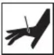
It is very dangerous for a staple to hit the hands or feet by mistake.
- Beware of the tool's kickback.
Do not approach the top of the tool with your head etc. during operation. This is dangerous because the tool may recoil violently if the staple currently being driven in comes into contact with a previous staple or a knot in the wood.
- Be careful of double fire due to recoil.
If the push lever is unintentionally allowed to re-contact the workpiece following recoil, an unwanted fastener will be driven.
In order to avoid this undesirable double fire, pull the trigger rapidly and firmly.
- Take care when stapling thin boards or the corners of wood.
When stapling thin boards, the staples may pass right through, as may also be the case when stapling the corners of wood due to deviation of the staples. In such cases, always make sure that there is no one (and nobody's hands or feet; etc.) behind the thin board or next to the wood you are going to staple.
- Simultaneous staping on both sides of the same wall is dangerous.
Under no circumstances should stapling be performed on both sides of a wall at the same time. This would be very dangerous since the staples might pass through the wall and thus cause injuries.
- Do not use the power tool on scaffoldings, ladders.
The power tool shall not be used for specific application for example:
- when changing one driving location to another involves the use of scaffoldings, stairs, ladders or ladder alike constructions, e.g. roof laths,
- closing boxes or crates,
- fitting transportation safety systems e.g. on vehicles and wagons
- Remove all remaining fasteners and battery from stapler when:
1) doing maintenance and inspection;
2) checking proper operation of push lever and trigger;
3) clearing a jam;
4) it is not in use;
5) leaving work area;
6) moving it to another location; and
7) handing it to another person.
Never attempt to clear a jam unless you have removed battery and all remaining fasteners from the Stapler.
The Stapler should never be left unattended since people who are not familiar with the Stapler might handle it and injure the themselves.
-
Remove battery from stapler when loading staples.
-
The operating environment for this device is between 0°C and 40°C so ensure use within this temperature range. The device may fail to operate below 0°C or above 40°C.
-
Always charge the battery at a temperature of 0°C-40°C.
A temperature of less than 0^ C will result in over
charging which is dangerous. The battery cannot be charged at a temperature higher than 40^ C. The most suitable temperature for charging is that of 20^ C– 25^ C.
- Do not use the charger continuously.
When one charging is completed, leave the charger for about 15 minutes before the next charging of battery.
-
Do not allow foreign matter to enter the hole for connecting the rechargeable battery.
-
Never disassemble the rechargeable battery or charger.
-
Never short-circuit the rechargeable battery.
Short-circuiting the battery will cause a great electric current and overheat. It results in burn or damage to the battery.
- Do not dispose of the battery in fire.
If the battery is burnt, it may explode.
-
Using an exhausted battery will damage the charger.
-
Bring the battery to the shop from which it was purchased as soon as the post-charging battery life becomes too short for practical use. Do not dispose of the exhausted battery.
-
Do not insert objects into the air ventilation slots of the charger.
Inserting metal objects or inflammables into the charger air ventilation slots will result in electrical shock hazard or a damaged charger.
- NEVER allow magnets (or similar magnetic devices) to be adjacent to the stapler, because the stapler has a magnetic sensor inside.
Doing so will cause a failure or risk of injury by malfunction.
-
Resting the unit after continuous work.
-
The power tool is equipped with a temperature protection circuit to protect the motor. Continuous work may cause the temperature of the unit to rise, activating the temperature protection circuit and automatically stopping operation. If this happens, allow the power tool to cool before resuming use.
-
This product may cease to operate when an abnormality is detected. In such cases, check the items listed under "TROUBLESHOOTING" on page 15.
-
Do not look directly into the light.
Such actions could result in eye injury.
- Wipe off any dirt or grime attached to the lens of the LED light with a soft cloth, being careful not to scratch the lens.
Scratches on the lens of the LED light can result in decreased brightness.
- Make sure that the battery is installed firmly.
If it is at all loose it could come off and cause an accident.
- Do not use the product if the tool or the battery terminals (battery mount) are deformed.
Installing the battery could cause a short circuit that could result in smoke emission or ignition.
- Keep the tool's terminals (battery mount) free of swarf and dust.
- Prior to use, make sure that swarf and dust have not collected in the area of the terminals.
○ During use, try to avoid swarf or dust on the tool from falling on the battery.
○ When suspending operation or after use, do not leave the tool in an area where it may be exposed to falling swarf or dust.
Doing so could cause a short circuit that could result in smoke emission or ignition.
CAUTION ON LITHIUM-ION BATTERY
To extend the lifetime, the lithium-ion battery equips with the protection function to stop the output.
In the cases of 1 to 3 described below, when using this product, even if you are pulling the switch, the motor may stop. This is not the trouble but the result of protection function.
-
When the battery power remaining runs out, the motor stops. In such a case, charge it up immediately.
-
If the tool is overloaded, the motor may stop. In this case, release the switch of tool and eliminate causes of overloading. After that, you can use it again.
-
If the battery is overheated under overload work, the battery power may stop. In this case, stop using the battery and let the battery cool. After that, you can use it again.
Furthermore, please heed the following warning and caution.
WARNING
In order to prevent any battery leakage, heat generation, smoke emission, explosion and ignition beforehand, please be sure to heed the following precautions.
- Make sure that swarf and dust do not collect on the battery.
○ During work make sure that swarf and dust do not fall on the battery.
○ Make sure that any swarf and dust falling on the power tool during work do not collect on the battery.
○ Do not store an unused battery in a location exposed to swarf and dust.
Before storing a battery, remove any swarf and dust that may adhere to it and do not store it together with metal parts (screws, nails, etc.).
-
Do not pierce battery with a sharp object such as a nail, strike with a hammer, step on, throw or subject the battery to severe physical shock.
-
Do not use an apparently damaged or deformed battery.
-
Do not use the battery for a purpose other than those specified.
-
If the battery charging fails to complete even when a specified recharging time has elapsed, immediately stop further recharging.
-
Do not put or subject the battery to high temperatures or high pressure such as into a microwave oven, dryer, or high pressure container.
-
Keep away from fire immediately when leakage or foul odor are detected.
-
Do not use in a location where strong static electricity generates.
-
If there is battery leakage, foul odor, heat generated, discolored or deformed, or in any way appears abnormal during use, recharging or storage, immediately remove it from the equipment or battery charger, and stop use.
-
Do not immerse the battery or allow any fluids to flow inside. Conductive liquid ingress, such as water, can cause damage resulting in fire or explosion. Store your battery in a cool, dry place, away from combustible and flammable items. Corrosive gas atmospheres must be avoided.
-
Do not give a strong shock to the display panel or break it. It may lead to a trouble.
-
If alkaline lubricant or cutting fluid adheres to the battery, quickly wipe it off with a dry cloth. Failure to do so may result in damage or degradation of the case.
CAUTION
-
If liquid leaking from the battery gets into your eyes, do not rub your eyes and wash them well with fresh clean water such as tap water and contact a doctor immediately. If left untreated, the liquid may cause eye-problems.
-
If liquid leaks onto your skin or clothes, wash well with clean water such as tap water immediately. There is a possibility that this can cause skin irritation
-
If you find rust, foul odor, overheating, discolor, deformation, and/or other irregularities when using the battery for the first time, do not use and return it to your supplier or vendor.
WARNING
If a conductive foreign matter enters in the terminal of lithium ion battery, the battery may be shorted, causing fire. When storing the lithium ion battery, obey surely the rules of following contents.
○ Do not place conductive debris, nail and wires such as iron wire and copper wire in the storage case.
To prevent shorting from occurring, load the battery in the tool or insert securely the battery cover for storing until the ventilator is not seen.
REGARDING LITHIUM-ION BATTERY TRANSPORTATION
When transporting a lithium-ion battery, please observe the following precautions.
WARNING
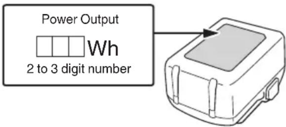
Notify the transporting company that a package contains a lithium-ion battery, inform the company of its power output and follow the instructions of the transportation company when arranging transport.
○ Lithium-ion batteries that exceed a power output of 100 Wh are considered to be in the freight classification of Dangerous Goods and will require special application procedures.
○ For transportation abroad, you must comply with international law and the rules and regulations of the destination country.
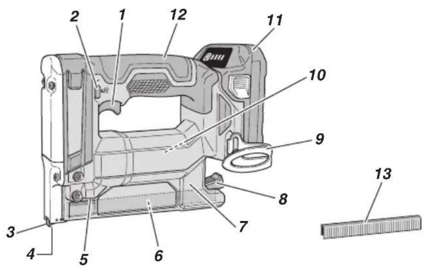
NAMES OF PARTS
The numbers in the list below correspond to Fig. 1–Fig. 13.
| 1 | Trigger |
| 2 | Trigger lock button |
| 3 | Push lever |
| 4 | Firing head (outlet) |
| 5 | LED light |
| 6 | Magazine base |
| 7 | Magazine |
| 8 | Stop lever |
| 9 | Hook |
| 10 | Motor |
| 11 | Battery |
| 12 | Handle |
| 13 | Staple strip |
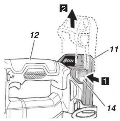
| 14 | Latch |
| 15 | Pilot lamp |
| 16 | Blade guide |
| 17 | Remaining battery indicator switch |
| 18 | Remaining battery indicator lamp |
| 19 | Display panel |
SYMBOLS
WARNING
The following show symbols used for the machine. Be sure that you understand their meaning before use.
 | N1810DA / N1812DA: Cordless Stapler |
 | To reduce the risk of injury, user must read instruction manual. |
 | Only for EU countriesDo not dispose of electric tools together with household waste material!In observance of European Directive 2012/19/EU on waste electrical and electronic equipment and its implementation in accordance with national law, electric tools that have reached the end of their life must be collected separately and returned to an environmentally compatible recycling facility. |
| Direct current | |
 | Switching ON |
 | Switching OFF |
 | Disconnect the battery |
 | Trigger locked |
 | Trigger unlocked |
 | Do not use on scaffoldings, ladders. |
 | Warning |

Prohibited action
Battery
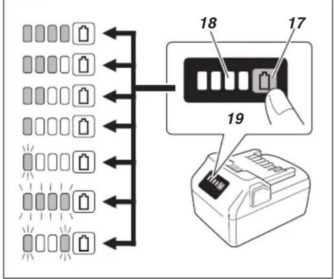
| 0000 | Lights;The battery remaining power is over 75%. |
| 0000 | Lights;The battery remaining power is 50%-75%. |
| 0000 | Lights;The battery remaining power is 25%-50%. |
| 0000 | Lights;The battery remaining power is less than 25%. |
 | Blinks;The battery remaining power is nearly empty.Recharge the battery soonest possible. |
 | Blinks;Output suspended due to high temperature.Remove the battery from the tool and allow it to fully cool down. |
 | Blinks;Output suspended due to failure or malfunction.The problem may be the battery so please contact your dealer. |
SPECIFICATIONS
- Power tool
| Model N1810DA / N1812DA | |
| Motor DC motor | |
| Staple Loading capacity 150 staples | |
| Weight*1 | 1.5 kg (BSL1820M)2.2 kg (BSL36B18X) |
| Dimension*2Length × Width × Height | 166 mm × 85 mm × 235 mm |
*1 Weight: According to EPTA-Procedure 01/2014 Depending on attached battery. The heaviest weight is measured with BSL36B18X (sold separately).
*2 Dimension: The battery BSL36A18X is included
2. Applicable staple
The staples indicated in the chart below can be used with this stapler.
150 staples are bonded together to form a strip.
Contact the dealer from which you purchased the stapler for details on obtaining the staples.
NOTE
Only staples manufactured by HiKOKI may be used. Staples other than those manufactured by HiKOKI may cause jamming and subsequent malfunctions.
English
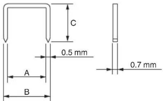
| A B C | |||
| N1810DA 9 mm 10 mm | 7 mm | ||
| 10 mm | |||
| N1812DA 12 mm 13 mm | 6 mm | ||
| 10 mm | |||
| 13 mm |
NOTE
Due to HiKOKI's continuing program of research and development, the specifications herein are subject to change without prior notice.
3. Battery (sold separately)
| Model Voltage Battery capacity | ||
| BSL1820M 18 V 2 | 0 Ah | |
STANDARD ACCESSORIES
In addition to the main unit (1 unit), the package contains the accessories listed on page 258.
Standard accessories are subject to change without notice.
APPLICATIONS
○ Securing the moisture-permeable waterproofing sheet in position
○ Securing the heat insulation material in position
CHARGING
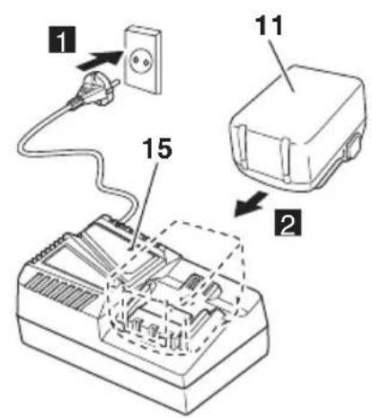
Before using the power tool, charge the battery as follows.
-
Connect the charger's power cord to the receptacle. When connecting the plug of the charger to a receptacle, the pilot lamp will blink in red. (See Table 1)
-
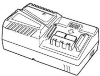
Insert the battery into the charger. Firmly insert the battery into the charger as shown in Fig. 3 (on page 2).
-
Charging When inserting a battery in the charger, charging will commence and the pilot lamp will light continuously in red. When the battery becomes fully recharged, the pilot lamp will blink in red. (See Table 1)
(1) Pilot lamp indication
The indications of the pilot lamp will be as shown in Table 1, according to the condition of the charger or the rechargeable battery.
Table 1: Indications of the pilot lamp
| ON/OFF at 0.5 sec. intervals | Before charging *1 or Charging complete |
| Lights continuously | While charging |
| Lights for 1 sec. at intervals of 0.5 sec. | Overheat standby *2 |
| ON/OFF at 0.1 sec. intervals | Charging impossible *3 |
NOTE
*1 If the red lamp continues to blink even after the charger has been attached, check to confirm that the battery has been fully inserted.
*2 Battery overheated. Unable to charge.
Although charging will start once the battery has cooled down even when left in situ, the best practice is to remove the battery and allow it to cool down in a shaded, well-ventilated location before charging.
*3 Malfunction in the battery or the charger
- Fully insert the battery.
- Check to confirm that no foreign matter is stuck to the battery mount or terminals. If there are no foreign objects, it is probable that the battery or charger is malfunctioning. Take it to your authorized Service Center.
If the pilot lamp does not blink in red even though the charger cord is connected to the power, it indicates that the protection circuit of the charger may be activated. Remove the cord or plug from the power and then connect it again after 5 minutes or so. If this does not cause the pilot lamp to blink in red, please take the charger to the HiKOKI Authorized Service Center.
When the battery charger has been continuously used, the battery charger will be heated, thus constituting the cause of the failures. Once the charging has been completed, give 15 minutes rest until the next charging.
(2) Regarding the temperatures and charging time of the battery. (See Table 2)
Table 2
| Model UC18YFSL | ||
| Type of battery Li-ion | ||
| Charging voltage 14.4–18 V | ||
| Temperatures at which the battery can be recharged | 0°C–50°C | |
| Charging time for battery capacity, approx. (At 20°C) | 1.5 Ah 22 min | |
| 2.0 Ah 30 min | ||
| 2.5 Ah 35 min | ||
| 3.0 Ah 45 min | ||
| 4.0 Ah 60 min | ||
| 5.0 Ah 75 min | ||
| Charging time for battery capacity, approx. (At 20°C) | 6.0 Ah 90 min | |
| Charging time for multi volt battery capacity, approx. (At 20°C) | 1.5 Ah (×2 unit) | 45 min |
| 2.5 Ah (×2 unit) | 75 min | |
| 4.0 Ah (×2 unit) | 120 min | |
| Number of battery cells 4–10 | ||
| Weight 0.5 kg | ||
NOTE
○ The recharging time may vary according to the ambient temperature and power source voltage.
○ If charging takes a long time
- Charging will take longer at extremely low ambient temperatures. Charge the battery in a warm location (such as indoors).
- Do not block the air vent. Otherwise the interior will overheat, reducing the charger's performance.
-
If the cooling fan is not operating, contact a HiKOKI Authorized Service Center for repairs.
-
Disconnect the charger's power cord from the receptacle.
-
Hold the charger firmly and pull out the battery. NOTE
Be sure to pull out the battery from the charger after use, and then keep it.
Regarding electric discharge in case of new batteries, etc.
As the internal chemical substance of new batteries and batteries that have not been used for an extended period is not activated, the electric discharge might be low when using them the first and second time. This is a temporary phenomenon, and normal time required for recharging will be restored by recharging the batteries 2–3 times.
How to make the batteries perform longer.
(1) Recharge the batteries before they become completely exhausted. When you feel that the power of the tool becomes weaker, stop using the tool and recharge its battery. If you continue to use the tool and exhaust the electric current, the battery may be damaged and its life will become shorter.
(2) Avoid recharging at high temperatures. A rechargeable battery will be hot immediately after use. If such a battery is recharged immediately after use, its internal chemical substance will deteriorate, and the battery life will be shortened. Leave the battery and recharge it after it has cooled for a while.
BEFORE USE
| Action Figure Page | ||
| Removing and inserting the battery 2 2 | ||
| Charging 3 2 | ||
| Remaining battery indicator 13 4 | ||
| Selecting accessories — 259 |
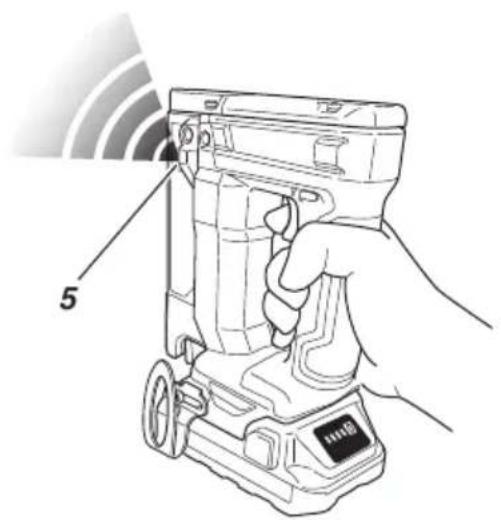
1. LED light warning signals (Fig. 4)
In case of operation error, LED light shows as below.
Table 3
| On 0.5 second/Off 0.5 second | Empty-firing prevention function was activated → Load staples.Battery voltage drop → Replace the battery. |
| On 0.25 second/Off 0.25 second | Overloaded condition (staple jam) → Remove the cause of the overloading.Temperature protection (stapler body is hot) → Allow the stapler body to cool sufficiently. |
| On 0.05 second/Off 0.05 second | Possibly malfunctioning→Request repairs from the dealer where it was purchased. |
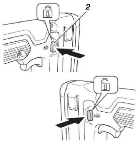
2. Trigger Lock Mechanism (See Fig. 5) WARNING
○ Make sure the trigger is locked when not firing staples.
- This Stapler has a lock mechanism to prevent the staples from being fired.
To lock the trigger:
Firmly press in the trigger lock button from the inside.
To operate:
Firmly press in the trigger lock button from the side. The lock is released and the trigger can be pulled.
3. Checking push lever operations WARNING
Make sure the trigger is locked when not firing staples. (See Fig. 5)
Always make sure the trigger is locked and the battery removed from the power tool when checking push lever operations.
Check to make sure the push lever slides smoothly when operated.
Clean the sliding area on the push lever if it doesn't slide smoothly.
4. Testing the stapler
WARNING
O Make sure the trigger is locked when not firing staples. (See Fig. 5)
O Never use Stapler unless push lever is operating properly.
Before actually beginning the stapling work, test the Stapler by using the checklist below. Conduct the tests in the following order.
If abnormal operation occurs, stop using the Stapler and contact a HiKOKI authorized service center immediately.
(1) REMOVE ALL STAPLES AND BATTERY FROM STAPLER.
- ALL SCREWS MUST BE TIGHTENED.
- THE PUSH LEVER AND TRIGGER MUST MOVE SMOOTHLY.
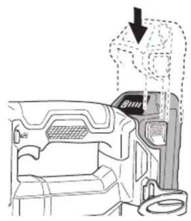
(2) Installing the battery. Do not operate the push lever or trigger while installing the battery. (See Fig. 2)
(3) Remove the finger from the trigger and press the push lever against the workpiece.
- THE STAPLER MUST NOT OPERATE.
English
(4) Separate the push lever from the workpiece. Next, point the stapler downward and release the trigger lock button, then pull the trigger and then wait in that position for 5 seconds or longer.
- THE STAPLER MUST NOT OPERATE.
(5)
A: Without touching the trigger, depress the push lever against the workpiece. Next, pull the trigger.
- THE STAPLER MUST OPERATE.
B: Hold the trigger back and depress the push lever against the workpiece again.
- THE STAPLER MUST NOT OPERATE.
C: Separate the finger from the trigger. Next, A is operated again.
- THE STAPLER MUST OPERATE.
(6) If no abnormal operation is observed, you may load staples in the Stapler. Drive staples into the workpiece that is the same type to be used in the actual application.
- THE STAPLER MUST OPERATE PROPERLY.
5. Loading staples
WARNING
When loading staples into Stapler,
1) remove battery from the stapler;
2) do not pull trigger; and
3) do not depress push lever.
NOTE
○ Do not simultaneously load staples of different lengths.
- Do not consecutively load several staple strips that have a small number of staples.
- Doing so may cause a staple jam or other problems.
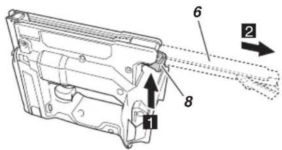
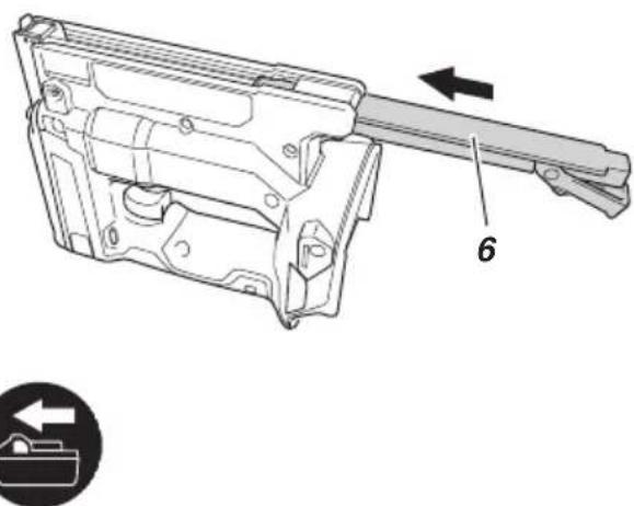
(1) Press the stop lever, and pull out the magazine base. (Fig. 6)
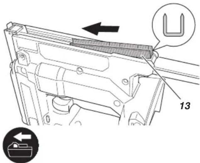
(2) Put the staples into the magazine with their legs pointed up. (Fig. 7)
(3) Press in the magazine base to its original position, and the stop lever will lock it. (Fig. 8)
NOTE
Gently close the magazine base. If it is closed forcefully, the staple strips may become deformed and prevent the magazine base from closing.
The Stapler is now ready to operate.
HOW TO USE THE STAPLER
WARNING
○ NEVER point tool at yourself or others in work area.
- Keep fingers AWAY from trigger when not driving staples to avoid accidental firing.
○ Do not use the electrical cord if damaged. Have it repaired immediately.
○ Never place your face, hands or feet near firing head when using.
○ Do not drive staples on top of other staples or with Stapler at too steep of an angle; staples can ricochet and hurt someone.
○ Do not drive staples into thin boards or near corners and edges of workpiece. Staples can be driven through or away from workpiece and hit someone.
Never drive staples from both sides of a wall at the same time. Staples can be driven into and through the wall and hit a person on the opposite side.
- Never use Stapler which is defective or operating abnormally.
O Do not use Stapler as hammer.
○ Remove all remaining staples and battery from stapler when:
1) doing maintenance and inspection;
2) checking proper operation of push lever and trigger;
3) cleaning a jam;
4) it is not in use;
5) leaving work area;
6) moving it to another location; and
7) handing it to another person.
○ Remove battery from Stapler when loading staples.
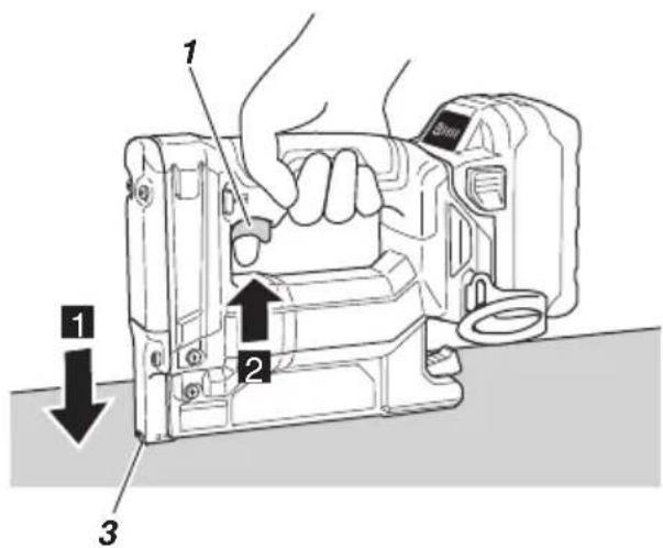
1. Stapling procedures (Fig. 9)
This Stapler is equipped with the push lever and does not operate unless the push lever is depressed. First, press the push lever against the wood; next, pull the trigger to drive the staple.
After stapling once, stapling will not be possible again until the trigger is released and pull again.
WARNING
- To avoid double firing or accidental firing due to recoil. Pull the trigger rapidly and firmly.
A: Position the staple outlet on the workpiece with finger off the trigger.
B: Depress the push lever firmly until it is completely depressed.
C: Pull the trigger to drive a staple.
D: Remove finger from the trigger and lift the tool off the wood surface completely.
To continue stapling in a separate location, move the stapler along the wood, repeating from the step A as required.
NOTE
Operations B and C should be done within 4 seconds of each other. If more than 4 seconds pass after B, the Stapler will not work properly. If this happens, retry from B.
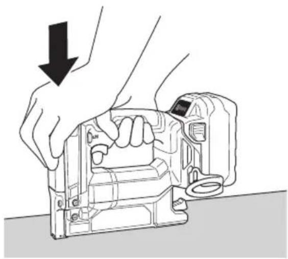
○ If the staples are not being driven in completely, firmly press down on the head of the stapler when firing.
(Fig. 10)
WARNING
Keep your finger off the trigger except during stapling operation, because serious injury could result if the push lever accidentally contacts you or others in work area.
Keep hands and body away from the discharge area. This HiKOKI stapler may bounce from the recoil of driving a staple and unwanted subsequent staple may be driven, possibly causing injury.
NOTE
○ Always handle staples and package carefully. If staples are dropped, collating bond may be broken, which will cause mis-feeding and jamming.
○ After stapling:
1) remove battery from the Stapler;
2) remove all staples from the Stapler;
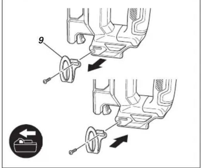
2. Using the hook (See Fig. 11)
WARNING
When using the hook, remove the battery. Pay sufficient attention so that the main equipment does not fall. If the tool falls, there is a risk of accident.
Hook can be installed on the left or right side.
A: Remove the battery, then remove all remaining staples from the magazine.
B: Securely hold the main unit and remove the screw using a screwdriver.
C: Remove the hook.
D: Install the hook on the other side and securely fasten with screw.
NOTE
Hook can be used as a hanger.
MAINTENANCE AND INSPECTION
WARNING
Be sure to remove all remaining staples, lock the trigger, and remove the battery from the stapler before maintenance and inspection.
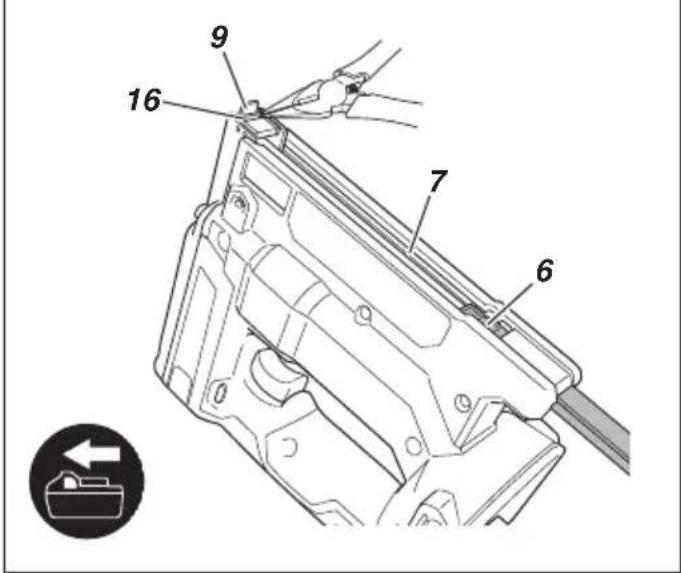
1. Removing Staple Jams (Fig. 12)
(1) Remove the battery from the power tool.
(2) Press the stop lever, slide open the magazine base and remove all remaining staples.
(3) Remove any jammed staples, adhesive of staples, fragments, and splinters that have collected in the blade guide with pliers, etc.
(4) Check to ascertain that the push lever works smoothly.
NOTE
After removing staple jams, reload the staples and fire a test staple.
2. Magazine Inspections
The inside of the magazine needs to be cleaned from time to time. Slide the magazine base open and remove adhesive of staples, fragments and splinters that have collected.
NOTE
Dirt inside the magazine may result in trouble with movement of staples or cause empty firing.
- Maintenance chart
| ACTION WHY | HOW | |
| Clean magazine and feeder mechanism. | Prevent a jam. Blow clean daily. | |
| Keep push lever working properly. | Promote operator safety and efficient Stapler operation. | Blow clean daily. |
4. Inspecting the mounting screws
Regularly inspect all mounting screws and ensure that they are properly tightened. Should any of the screws be loose, retighten them immediately. Failure to do so could result in serious hazard.
5. Maintenance of the motor
The motor unit winding is the very “heart” of the power tool. Exercise due care to ensure the winding does not become damaged and/or wet with oil or water.
6. Cleaning on the outside
When the power tool is stained, wipe with a soft dry cloth or a cloth moistened with soapy water. Do not use chloric solvents, gasoline or paint thinner, for they melt plastics.
7. Storage
Store the power tool and battery in a place in which the temperature is less than 40^ C and out of reach of children.
NOTE
Storing lithium-ion batteries. Make sure the lithium-ion batteries have been fully charged before storing them. Prolonged storage (3 months or more) of batteries with a low charge may result in performance deterioration, significantly reducing battery usage time or rendering the batteries incapable of holding a charge.
However, significantly reduced battery usage time may be recovered by repeatedly charging and using the batteries two to five times.
If the battery usage time is extremely short despite repeated charging and use, consider the batteries dead and purchase new batteries.
CAUTION
In the operation and maintenance of power tools, the safety regulations and standards prescribed in each country must be observed.
Important notice on the batteries for the HiKOKI cordless power tools
Please always use one of our designated genuine batteries. We cannot guarantee the safety and performance of our cordless power tool when used with batteries other than these designated by us, or when the battery is disassembled and modified (such as disassembly and replacement of cells or other internal parts).
GUARANTEE
We guarantee HiKOKI Power Tools in accordance with statutory/country specific regulation. This guarantee does not cover defects or damage due to misuse, abuse, or normal wear and tear. In case of complaint, please send the Power Tool, undismantled, with the GUARANTEE CERTIFICATE found at the end of this Handling instruction, to a HiKOKI Authorized Service Center.
Noise Information
Noise characteristic values in accordance with EN60745: The typical A-weighted single-event sound power level
LWA,1s,d = 78 dB
The typical A-weighted single-event emission sound pressure level at work station LpA, 1s, d = 67 dB Uncertainty KpA: 3 dB
These values are tool-related characteristic values and do not represent the noise development at the point of use. Noise development at the point of use will for example depend on the working environment, the workpiece, the workpiece support and the number of driving operations, etc.
Depending on the conditions at the workplace and the form of the workpiece, individual noise attenuation measures may need to be carried out, such as placing workpieces on sound-damping supports, preventing workpiece vibration by means of clamping or covering, etc.
In special cases it is necessary to wear hearing protection equipment.
Vibration Information
The typical vibration characteristic value in accordance with EN60745: 1.7 m/s ^2
Uncertainty K: 1.5 m/s²
This values is a tool-related characteristic value and does not represent the influence to the hand-arm-system when using the tool. An influence to the hand-arm-system when using the tool will for example depend on the gripping force, the contact pressure force, the working direction, the adjustment of energy supply, the workpiece, the wrokpiece support.
The declared vibration total value has been measured in accordance with a standard test method and may be used for comparing one tool with another. It may also be used in a preliminary assessment of exposure.
WARNING
○ The vibration emission during actual use of the power tool can differ from the declared total value depending on the ways in which the tool is used.
○ Identify safety measures to protect the operator that are based on an estimation of exposure in the actual conditions of use (taking account of all parts of the operating cycle such as the times when the tool is switched off and when it is running idle in addition to the trigger time).
NOTE
Due to HiKOKI's continuing program of research and development, the specifications herein are subject to change without prior notice.
TROUBLESHOOTING
Use the inspections in the table below if the tool does not operate normally. If this does not remedy the problem, consult your dealer or the HiKOKI Authorized Service Center.
| PROBLEM CHECK METHOD CORRECTION | ||
| Stapler doesn't operate. Stapler not enough | ough pressed against workpiece. | Hold stapler firmly and press to the workpiece completely. |
| Trigger not enough pulled. Pull the trigger firmly. | ||
| More than 4 seconds pass from push lever ON to trigger ON. | Make sure that less than 4 seconds pass between push lever ON and trigger ON. | |
| Trigger lock button (Trigger lock function) is “Lock” position. | Set trigger lock button to “Unlock” position. (Refer to Fig. 6) | |
| Damaged internal electronics. Contact HiKOKI for replacement. | ||
| Stapler operates, but no staple is driven. | Magazine is dirty. Blow and wipe clean the magazine. | |
| Check for a jam. Clear a jam (refer to Fig. 12). | ||
| Driver blade worn or damaged? Contact HiKOKI for replacement. | ||
| Check for proper staples. Use only recommended staples. | ||
| Skipping staples. Intermittent feed. | Check for proper staples. Use only recommended staples. | |
| Staple feeder damaged? Replace staple feeder. | ||
| Feed spring weakened or damaged? Replace feed spring. | ||
| Driver blade worn or damaged? Contact HiKOKI for replacement. | ||
| Staples jam. Driven staple is bent. | Check for proper staples. Use only recommended staples. | |
| Driver blade worn or damaged? Contact HiKOKI for replacement. | ||
ALLGEMEINE
natural_image
Simple line drawing of a rectangular device with a central screen and side connectors (no text or symbols)VEILIGHEIDSWAARSCHUWINGEN VOOR ACCU NIETAPPARAAT
VEILIGHEIDSWAARSCHUWINGEN
natural_image
Simple line drawing of a rectangular device with a central screen and side connectors (no text or symbols)NAMEN VAN ONDERDELEN
- HET NIETAPPARAAT MOET IN WERKING TREDEN.
Nederlands
- HET NIETAPPARAAT MOET IN WERKING TREDEN.
1. LED light warning signals (Fig. 4)
(1) Pilot lamp indication
- KLAMMEPISTOLEN MÅ IKKE VÆRE I DRIFT.
- KLAMMEPISTOLEN MÅ IKKE VÆRE I DRIFT.
(5)
- KLAMMEPISTOLEN SKAL VÆRE I DRIFT.
- KLAMMEPISTOLEN MÅ IKKE VÆRE I DRIFT.
- KLAMMEPISTOLEN SKAL VÆRE I DRIFT.
VEDLIKEHOLD OG INSPEKSJON
ADVARSEL
natural_image
Simple line drawing of a rectangular device with a central screen and side connectors (no text or symbols)PARÇA ADLARI
| Model Tensiune | Capacitateacumulator |
| BSL1820M 18 V 2,0 Ah |
ACCESORII STANDARD
natural_image
Line drawing of a battery pack with display and control panel (no text or symbols)BSL18.. UC18YFSL (14,4 V–18 V)
natural_image
Line drawing of a mechanical device with internal compartments and ports (no text or symbols)
329897
natural_image
Line drawing of a quill pen in an inkwell (no text or symbols)| English | Dansk | Română | |||
| GUARANTEE CERTIFICATE1 Model No.2 Serial No.3 Date of Purchase4 Customer Name and Address5 Dealer Name and Address(Please stamp dealer name and address) | GARANTIBEVIS1 Modelnummer2 Serienummer3 Købsdato4 Kundes navn og adresse5 Forhandlers navn og adresse(Indsæt stempel med forhandlers navn og adresse) | CERTIFICAT DE GARANTIE1 Model nr.2 Nr. de serie3 Data cumpărării4 Numele și adresa clientului5 Numele și adresa distribuitorului(Vă rugăm aplicați štampila cu numele și adresa distribuitorului) | |||
| Deutsch | Norsk | Slovenščina | |||
| GARANTIESCHEIN1 Modell-Nr.2 Serien-Nr.3 Kaufdatum4 Name und Anschrift des Kunden5 Name und Anschrift des Händlers(Bitte mit Namen und Anschrift des Handlers abstempeln) | GARANTISERTIFIKAT1 Modellnr.2 Serienr.3 Kjøpsdato4 Kundens navn og adresse5 Forhandlerens navn og adresse(Vennligst stemple forhandlerens navn og adresse) | GARANCIJSKO POTRDILO1 Št. modela2 Serijska št.3 Datum nakupa4 Ime in naslov kupca5 Ime in naslov prodajalca(Prosimo vitisnite žig z imenom in naslovom prodajalca) | |||
| Français | Suomi | Slovenčina | |||
| CERTIFICAT DE GARANTIE1 No. de modèle2 No de série3 Date d'achat4 Nom et adresse du client5 Nom et adresse du revendeur(Cachet portant le nom et l'adresse du revendeur) | TAKUUTODISTUS1 Malli nro2 Sarja nro3 Ostopăivămâäră4 Asiakkaan nimi ja osoite5 Myyjăn nimi ja osoite(Leimaa myyjăn nimi ja osoite) | ZÁRUČNÝ LISTA1 Č. modelu2 Sériové č.3 Dátum zakúpenia4 Meno a adresa zákazníka5 Názov a adresa predajcu(Pečiatka s názvom a adresou predajcu) | |||
| Italiano | Ελληνικά | Български | |||
| CERTIFICATO DI GARANZIA1 Modello2 N° di serie3 Data di acquisto4 Nome e indirizzo dell'acquirente5 Nome e indirizzo del rivenditore(Si prega di apporre il timbro con questi dati) | ПІЗТОПОІНТИКО ЕГГУНЄНЕ1 Ap. Movtėlou2 Aŭξων Ap.3 Нμερομηνία αγοράς4 ́Оvoμα και διεύθυνση πελάτη5 ́Оvoμα και διεύθυνση μεταπωλητή(Παρακαλούμε να χρησιμοποιηθεί σφραγίδα) | ГАРАНЦИОНЕН СЕРТИФИКАТ1 Модел No2 Сериен No3 Дата за закупуване4 Име и адрес на клиента5 Име и адрес на търговеца(Моля, отпечатайте името и адрес на дильра) | |||
| Nederlands | Polski | Srpski | |||
| GARANTIEBEWIJS1 Modelnummer2 Serienummer3 Datum van aankoop4 Naam en adres van de gebruiker5 Naam en adres van de handelaar(Stempel a.u.b. naam en adres vande de handolaar) | GWARANCJA1 Model2 Numer seryjny3 Data zakupu4 Nazwa klienta i adres5 Nazwa dealera i adres(Pieczęć punktu sprzedaży) | GARANTNI SERTIFIKAT1 Br. modela.2 Serijski br.3 Datum kupovine4 Ime i adresa kupca5 Ime i adresa prodavca(Molimo da stavite pečat na ime i adresu trgovca) | |||
| Español | Magyar | Hrvatski | |||
| CERTIFICADO DE GARANTÍA1 Número de modelo2 Número de serie3 Fecha de adquisición4 Nombre y dirección del cliente5 Nombre y dirección del distribuidor(Se ruega poner el sello del distribuidor con su nombre y dirección) | GARANCIA BIZONYLAT1 Tipusszám2 Sorozatszám3 A vásárlás dátuma4 A Vásárló neve és címe5 A Kereskedő neve és címe(Kérjük ide elhelyezni a Kereskedő nevének és címének pecsétjét) | JAMSTVENI CERTIFIKAT1 Br modela.2 Serijski br.3 Datum kupnje4 Ime i adresa kupca5 Ime i adresa trgovca(Molimo stavite pečat na ime i adresu trgovca) | |||
| Português | Čeština | ||||
| CERTIFICADO DE GARANTIA1 Número do modelo2 Número do série3 Data de compra4 Nome e morada do cliente5 Nome e morada do distribuidor(Por favor, carímbe o nome e morada do distribuidor) | ZÁRUČNÍ LIST1 Model č.2 Série č.3 Datum nákupu4 Jméno a adresa zákazníka5 Jméno a adresa prodejce(Prosíme o razítko se jménem a adresou prodejce) | ||||
| Svenska | Türkçe | ||||
| GARANTICERTIFIKAT1 Modellnr2 Serienr3 Inköpsdatum4 Kundens namn och adress5 Försäljarens namn och adress(Stämpla försäljarens namn och adress) | GARANTI SERTÍFİKASI1 Model No.2 Seri No.3 Satin Alma Tarihi4 Müşteri Adı ve Adresi5 Bayi Adı ve Adresi(Lütfen bayi adını ve adresini kaşe olarak basın) | ||||
HiKOKI
| 1 | |
| 2 | |
| 3 | |
| 4 | |
| 5 |
Siemensring 34, 47877 willich, Germany
Tel: +49 2154 49930
Fax: +49 2154 499350
URL: http://www.hikoki-powertools.de
Hikoki Power Tools Netherlands B.V.
Brabanthaven 11, 3433 PJ Nieuwegein, The Netherlands
Tel: +31 30 6084040
Fax: +31 30 6067266
URL: http://www.hikoki-powertools.nl
Hikoki Power Tools (U.K.) Ltd.
25 Majestic Road, Southampton, SO16 OYT,
United Kingdom
Tel: +44 1908 660663
Fax: +44 1908 606642
URL: http://www.hikoki-powertools.uk
Hikoki Power Tools France S.A.S.
Hikoki Power Tools Belgium N.V./S.A.
Koningin Astridlaan 51, B-1780 Wemmel, Belgium
Tel: +32 2 460 1720
Fax: +32 2 460 2542
URL: http://www.hikoki-powertools.be
Hikoki Power Tools Italia S.p.A
Via Piave 35, 36077, Altavilla Vicentina (VI), Italy
Tel: +39 0444 548111
Fax: +39 0444 548110
URL: http://www.hikoki-powertools.it
Hikoki Power Tools Ibérica, S.A.
C/ Puigbarral, 26-28, Pol. Ind. Can Petit, 08227 Terrassa
(Barcelona), Spain
Tel: +34 93 735 6722
Fax: +34 93 735 7442
URL: http://www.hikoki-powertools.es
Kjeller Vest 7, N-2007 Kjeller, Norway
Tel: (+47) 6692 6600
Fax: (+47) 6692 6650
URL: http://www.hikoki-powertools.no
Hikoki Power Tools Sweden AB
Rotebergsvagen 2B SE-192 78 Sollentuna, Sweden
Tel: (+46) 8 598 999 00
Fax: (+46) 8 598 999 40
URL: http://www.hikoki-powertools.se
Hikoki Power Tools Denmark A/S
Lillebaeltsvej 90, 6715 Esbjerg N, Denmark
Tel: (+45) 75 14 32 00
Fax: (+45) 75 14 36 66
URL: http://www.hikoki-powertools.dk
Hikoki Power Tools Finland Oy
Tupalankatu 9, 15680 Lahti, Finland
Tel: (+358) 20 7431 530
Fax: (+358) 20 7431 531
URL: http://www.hikoki-powertools.fi
Hikoki Power Tools Hungary Kft.
Hikoki Power Tools Romania S.R.L.
Ring Road, No. 66, Mustang Traco Warehouses,
Warehouse No.1, Pantelimon City, 077145, Ilfov County, Romania
natural_image
Line drawing of a quill pen in an inkwell (no text or symbols)natural_image
Three black-and-white icons: a person recycling with arrows, a rectangular object resembling a pencil, and a trash can with an 'Recycle' symbol (no text or numbers present)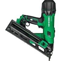
- GENERAL POWER TOOL SAFETY WARNINGS
- WARNING
- Save all warnings and instructions for future reference.
- 1) Work area safety
- 2) Electrical safety
- 3) Personal safety
- 4) Power tool use and care
- 5) Battery tool use and care
- English
- PRECAUTION
- CORDLESS STAPLER SAFETY WARNINGS
- ADDITIONAL SAFETY WARNINGS
- CAUTION ON LITHIUM-ION BATTERY
- CAUTION
- REGARDING LITHIUM-ION BATTERY TRANSPORTATION
- NAMES OF PARTS
- SYMBOLS
- SPECIFICATIONS
- Applicable staple
- NOTE
- Battery (sold separately)
- STANDARD ACCESSORIES
- APPLICATIONS
- CHARGING
- Pilot lamp indication
- Regarding electric discharge in case of new batteries, etc.
- How to make the batteries perform longer.
- BEFORE USE
- LED light warning signals (Fig. 4)
- Trigger Lock Mechanism (See Fig. 5) WARNING
- Checking push lever operations WARNING
- Testing the stapler
- Loading staples
- HOW TO USE THE STAPLER
- Stapling procedures (Fig. 9)
- (Fig. 10)
- Using the hook (See Fig. 11)
- MAINTENANCE AND INSPECTION
- Removing Staple Jams (Fig. 12)
- Magazine Inspections
- Inspecting the mounting screws
- Maintenance of the motor
- Cleaning on the outside
- Storage
- Important notice on the batteries for the HiKOKI cordless power tools
- GUARANTEE
- Noise Information
- Vibration Information
- TROUBLESHOOTING
- ALLGEMEINE
- VEILIGHEIDSWAARSCHUWINGEN VOOR ACCU NIETAPPARAAT
- VEILIGHEIDSWAARSCHUWINGEN
- NAMEN VAN ONDERDELEN
- Nederlands
- VEDLIKEHOLD OG INSPEKSJON
- ADVARSEL
- PARÇA ADLARI
- ACCESORII STANDARD
- Hikoki Power Tools Netherlands B.V.
- Hikoki Power Tools (U.K.) Ltd.
- Hikoki Power Tools France S.A.S.
- Hikoki Power Tools Belgium N.V./S.A.
- Hikoki Power Tools Italia S.p.A
- Hikoki Power Tools Ibérica, S.A.
- Hikoki Power Tools Sweden AB
- Hikoki Power Tools Denmark A/S
- Hikoki Power Tools Finland Oy
- Hikoki Power Tools Hungary Kft.
- Hikoki Power Tools Romania S.R.L.
Brand : HiKOKI
Model : N1810DA
Category : Stapler