OV 1800 - Oven DOMETIC - Free user manual and instructions
Find the device manual for free OV 1800 DOMETIC in PDF.

User questions about OV 1800 DOMETIC
0 question about this device. Answer the ones you know or ask your own.
Ask a new question about this device
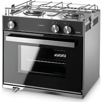
Download the instructions for your Oven in PDF format for free! Find your manual OV 1800 - DOMETIC and take your electronic device back in hand. On this page are published all the documents necessary for the use of your device. OV 1800 by DOMETIC.
USER MANUAL OV 1800 DOMETIC
natural_image
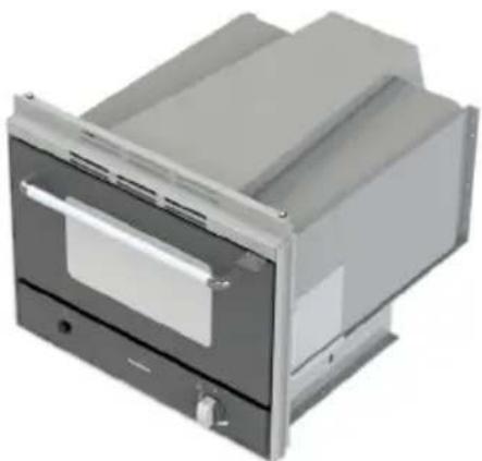
3D rendering of a stainless steel oven with open door and control panel (no text or symbols visible)OVG340I
natural_image
3D rendering of a stainless steel oven or oven unit with a flat lid and control panel (no visible text or symbols)OV1800 - OVN1800I
IT
Forno
Installation, Use, and Maintenance ..... 25
FR
Four
Installation, Usage, Entretien ....41
DE
Backofen
2
OVG340I
FRONT VIEW SIDE VIEW
OV1800 - OVN1800I
FRONT VIEW SIDE VIEW
3
4
OVG340I
natural_image
Technical line drawing of a mechanical oven or rack unit with internal slatted structure and mounting base (no text or symbols)OV1800 - OVN1800I
natural_image
Technical line drawing of a mechanical assembly with mounting brackets and internal components (no text or symbols)5
6
natural_image
Technical line drawing of a mechanical device with structural supports and a control panel (no text or symbols)7
natural_image
Close-up of hands using a wrench to adjust a mechanical component (no text or symbols visible)Please read this instruction manual carefully before using the appliance. If the appliance is given to another party, the instruction manual must also be provided.
Table of contents
1 Explanation of symbols....26
2 General safety instructions....26
3 Contents of supply....27
4 Intended use....27
5 Installation....28
5.1 Installation hole 28
5.2 Gas connection....29
5.3 Electrical connections....30
5.4 Fixing 30
6 Technical description....31
6.1 Control panel....31
6.2 Burners 32
7 Use ....33
7.1 Additional safety warnings....33
7.2 Oven....34
7.3 Grill (if present)....36
7.4 Visual inspection of the flame....37
7.5 Accessories 37
7.6 Gas cylinders....38
8 Cleaning and maintenance ....39
8.1 Cleaning the appliance....39
8.2 Replacing injectors 40
9 Warranty ....40
1 Explanation of symbols

CAUTION!
Security warning: Ignoring this warning could cause serious injury or death.

IMPORTANT!
Failure to observe this note can cause material damages and affect the operation of the product.

NOTE
Additional information relative to the use of the product.
Action: this symbol indicates that action is required on your part. The required action is described step-by-step.
Fig. 1 5, page 3: this information refers to an element in a figure; in this case, the figure is found in "position 5 in figure 1 on page 3".
2 General safety instructions
The manufacturer does not assume any liability for damages in the following cases:
● damage to the product resulting from improper use
- changes to the product without express permission from the manufacturer
- use for purposes other than those described in the operating manual
• non-compliant installation and/or connections
- This warning is located on the appliance.
- This appliance must be installed according to the regulations in force and used only in a well ventilated area.
- Refer to the instructions before installing and using this appliance.
- The appliance must be installed by specialised technicians.

CAUTION!
Use the appliance in accordance with the intended use.
3 Contents of supply
| Reference | Quantity Name |
| Fig. 1, page 2 | |
| 11 Oven | |
| 21 Top panel (OVG340l) | |
| 31 Fixing screw bag | |
| 41 Drip pan | |
| 51 Oven rack | |
| 1 Instructions manual | |
4 Intended use

CAUTION!
This appliance can only be used to cook food. Any other use is deemed incorrect and therefore hazardous. The manufacturer declines liability for damage to property and injury to persons caused by improper, incorrect or irresponsible use.
5 Installation

CAUTION!
Before installation, check that the local distribution conditions (gas type and pressure) and the settings of the appliance compatible.
The adjustment conditions for this appliance are provided on the label (or on the data plate).
This appliance is not connected to a combustion product evacuation system. It must be installed and connected in accordance with the installation rules in force. Special attention must be given to relevant ventilation governing provisions.
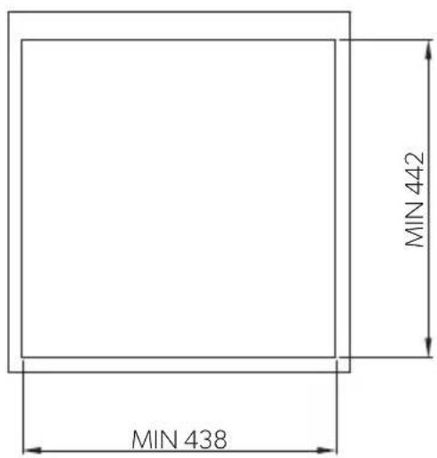
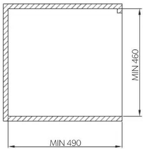
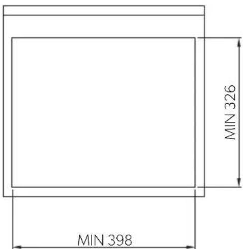
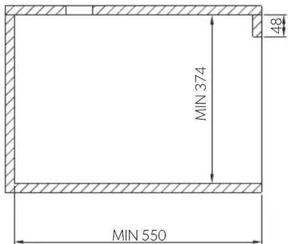
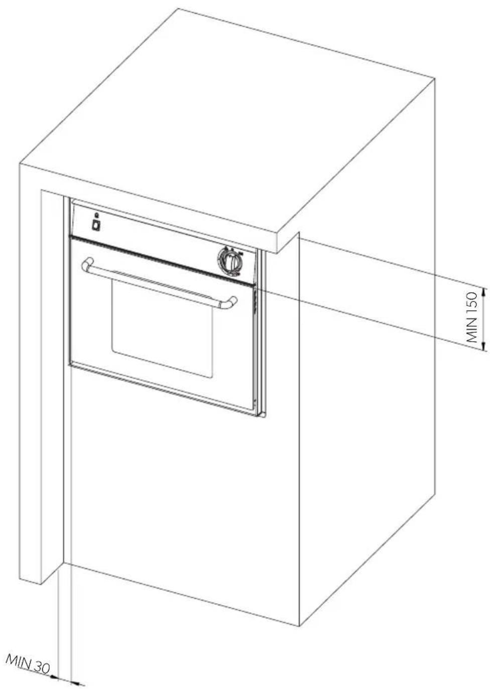
5.1 Installation hole

CAUTION!
The appliance should be kept away from flammable materials.
This appliance belongs to CLASS 3: APPLIANCE TO BE BUILT INTO A KITCHEN UNIT OR WORKTOP.
Minimum distances to observe from the walls
Distance Position
150 mm From the top edge of the door to the top horizontal wall.
30 mm From the side edge of the door to the adjacent vertical wall.
Built in hole dimensions
Depending on the model, make a hole in the cabinet as shown in Fig. 2, page 3.
The cabinet must be parallel to and flush with the horizontal worktop.
The cabinet built-in hole must be parallel. If the cabinet has aeration openings, prevent combustible materials from accessing these openings.
5.2 Gas connection

CAUTION!
Check this data before connecting the appliance to the gas cylinder. Pressure reducing valves to be used between the gas cylinder and the appliance must conform to the categories listed in the table below.
This appliance can be operated with the gases and related pressures described in the following table. The identification label glued to the appliance clearly shows the category (or categories) according to which the appliance has been adjusted.
| CATEGORY AND COUNTRIES OF DESTINATION | GAS PRESSURE |
| 13B/P(30) | 30 mbar Butane (G30) |
| AT BE DE DK FI GB NL NO PT SE SI | 30 mbar Propane (G31) |
| 13+ (28-30/37) | 28-30 mbar Butane (G30) |
| BE CH ES FR GB IE IT PT SI | 37 mbar Propane (G31) |
| MODEL NOMINAL AND COMPLETEHEAT OUTPUTkW - gr/h | VOLUME OF AIRREQUIRED FORCOMBUSTION m^3/h |
OVG340I 1.6 - 115 3.2
OV1800 1.1 - 80 2.2
OVN1800I 1.1 - 80 2.2

CAUTION!
During installation and connection, the gas conductor of the appliance must not be subject to twisting, pulling or other stresses.
The gas pipeline connection to the appliance must be done using a rigid metal pipe and sealing connections.
It is possible to use a hose, but it must:
- Allow for inspection at all times.
- Be protected from possible contact with heatable parts (such as the underside of the burners).
- Be protected from any stress (torsion, tensile, compression, etc.).
- Be protected from the moving parts of the cabinet (e.g. a drawer).
- Have a maximum length of 1.5 m.
- Be replaced before its expiration date.
Once connected, check the gas circuit seal by using a non-corrosive fluid to detect any leaks. Do not use a soap and water solution. DO NOT USE AN OPEN FLAME.
5.3 Electrical connections

CAUTION!
This appliance must be connected to a 12 V power pack. If a 2 x 0,5 mm ^2 cable is used for the connection, its length must not exceed 2 meters. When wiring the appliance respect correct polarity!

CAUTION!
Never connect the appliance to the main voltage (230 V\~); this would result in the ultimate destruction of the parts and a hazard to the user.
To connect the appliance, use a double cable and connect it to the terminal board identified with "+12 V =", found on the back side of the appliance. The red terminal is the positive pole, while the black terminal is the negative pole.
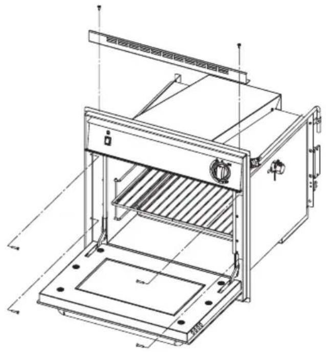
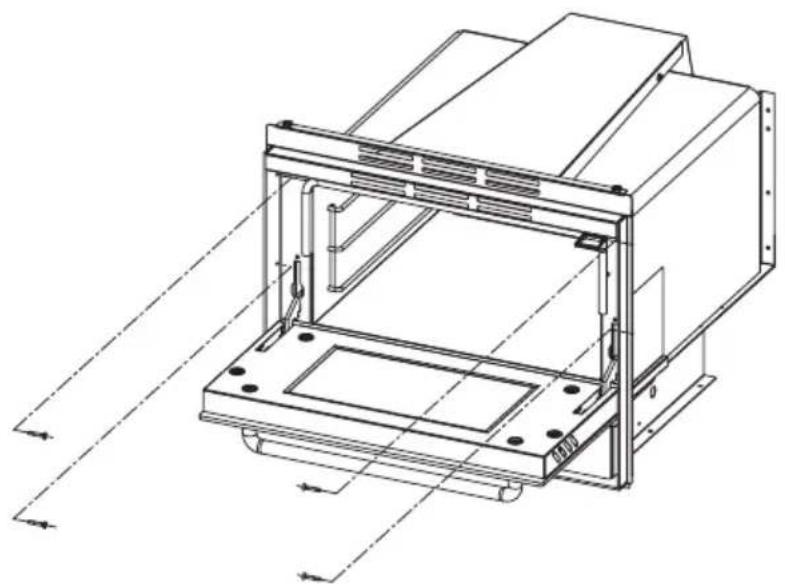
5.4 Fixing

CAUTION!
This appliance must be fixed to the cabinet using the screws as described in Fig. 4, page 5.
6 Technical description
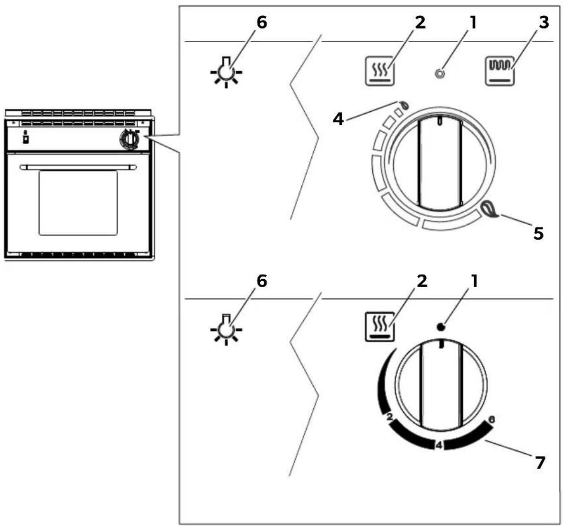
6.1 Control panel
The following table shows all the buttons and symbols on the appliance.

NOTE
Buttons and symbols may vary depending on the model.
Reference
Fig. 5, page 6
Symbol Description
1 Gas turned off.

2 Indicates the oven control kn

3 Indicates the grill control kno

4 Minimum adjustment of the flame.
5 Maximum adjustment of the flame.
6 Button to turn on the oven light.

72-4-6 Oven Temperature
6.2 Burners
| MODEL | HEAT OUTPUT | |||
| GRILL OVEN | ||||
| kW gr/h | kW gr/h | |||
| OVG340I | 1.6 115 1.1 | 80 | ||
| OV1800 | --1.180 | |||
| OVN1800I | --1.180 | |||
7 Use
7.1 Additional safety warnings

CAUTION!
This appliance must only be used by responsible adults. The accessible parts may be hot during and immediately after use; do not touch them and keep children away. After cooking, return the knob(s) to the closed position(s). After use, close the main gas line tap.

CAUTION!
This appliance may not be used by people (including children) with impaired physical and mental capacities, or with no experience in using electrical appliances, unless they are supervised and instructed by a person who is responsible for their safety. Children must be controlled to make sure they do not play with the appliance.
The use of a gas cooking appliance leads to the generation of heat and moisture in the room in which it is installed. Make sure to provide good ventilation in the kitchen: keep natural ventilation openings open or install a mechanical ventilation device (mechanical extractor hood).
Intense and prolonged use of the appliance may require supplementary aeration such as the opening of a window or more effective ventilation such as an increase in the power of the possible mechanical extractor hood.

CAUTION!
Inadequate ventilation creates hazard to the user and risk for injury.

IMPORTANT!
When cooking food for the first time, leave the oven and the grill on at maximum capacity. The oven must be kept on for at least 30 minutes and the grill must be kept on for 15-20 minutes.
7.2 Oven

CAUTION!
The burner must only be ignited when the door is fully open.
The rack, drip pan (tray) or the pan must be positioned in the oven in a way that they are not directly in contact with the flames.
If the burner flame accidentally goes out, close the gas knob and wait a minute before relighting.
Electronic ignition of the oven
To turn on the flame, fully press the control knob and rotate from the minimum flame to the maximum flame position (Fig. 5, page 6).
Once the flame has been generated, press the knob down for a few seconds so that the flame remains lit.

CAUTION!
If the burner does not turn on:
• proceed with manual ignition;
- check that there is gas in the cylinder.
If the device does not work, close the gas inlet tap and contact your dealer.
Manual ignition of the oven
If the electronic ignition does not work, the manual ignition is used as a substitute.
To turn on the flame, fully press the control knob and rotate from the minimum flame to the maximum flame position (Fig. 5, page 6).
▶ Simultaneously ignite the burner with a match or gas lighter.
Once the flame has been generated, press the knob down for a few seconds so that the flame remains lit.

CAUTION!
If the burner does not turn on:
- check that there is gas in the cylinder.
If the device does not work, close the gas inlet tap and contact your dealer.
Regulating the oven flame
To adjust the flame, turn the knob to the desired position (Fig. 5, page 6).
| OVG340I | ||
| Position | ||
| Temperature 120 °C 240 °C | ||
| OV1800 - OVN1800I | |
| Position 246 | |
| Temperature 150 °C 200 °C 240 °C | |

NOTE
As soon as the oven burner flame is turned on, it remains at the maximum flow rate in all potions of the knob and then automatically decreases to the minimum flow rate when the set oven temperature is reached.
7.3 Grill (if present)

CAUTION!
The burner must only be ignited when the door is fully open.
If the burner does not light immediately, release the knob and repeat the operation after 10 seconds.
Never use the grill for more than 25 minutes. The grill cannot be used as an oven.
If the burner flame accidentally goes out, close the gas knob and wait a minute before relighting.
Accessible parts may be hot when the grill is used, keep children away.
Electronic ignition of the grill
To generate the flame, fully press down the control knob and turn it from position grill (Fig. 5, page 6).
Once the flame has been generated, press the knob down for a few seconds so that the flame remains lit.

CAUTION!
If the burner does not turn on:
• proceed with manual ignition;
- check that there is gas in the cylinder.
If the device does not work, close the gas inlet tap and contact your dealer.
Manual ignition of the grill
If the electronic ignition does not work, the manual ignition is used as a substitute.
To generate the flame, fully press down the control knob and turn it from position grill (Fig. 5, page 6).
▶ Simultaneously ignite the burner with a match or gas lighter.
Once the flame has been generated, press the knob down for a few seconds so that the flame remains lit.

CAUTION!
If the burner does not turn on:
- check that there is gas in the cylinder.
If the device does not work, close the gas inlet tap and contact your dealer.
Regulating the grill flame
The grill is to be used only at its rated thermal capacity.
7.4 Visual inspection of the flame
Depending on the type of gas used, the flame appears as follows:
• Propane (G31): flame with blue internal pin point and clear outline.
- Butane (G30): flame with slight yellow tips when igniting the burner; these tips intensify as the burner heats.
7.5 Accessories
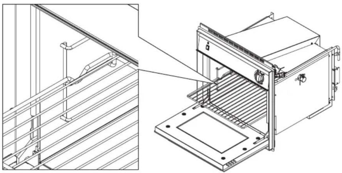
The rack and drip pan have a block that prevents accidental extraction (Fig. 6, page 7).
For a correct insertion, the blocks must be facing upwards and toward the inside of the appliance.
To extract, slightly lift the front of the rack or the drip pan.
7.6 Gas cylinders

CAUTION!
The use of gas and/or a pressure different from those indicated by the manufacturer could cause irregular and incorrect operation of the appliance. The manufacturer declines all liability for the incorrect or improper use of the appliance.
The gas cylinders to be used are the most common in the country where the appliance is used. The gas to be used is clearly indicated on the outside of the packaging and on the indelible label attached on the back of the appliance. In any case, observe the following: Gas cylinders with valve and pressure reducer must be placed in an upright position and in the appropriate compartment, and access should not be impeded. Replacement of the cylinders must be performed without impediment and with ease.
Replacing the gas cylinder
▶ Close the taps of the appliance.
▶ Make sure no flames or fire are nearby.
▶ Close the valve of the cylinder to be replaced.
Unscrew the pressure reducer of the empty cylinder, take it out of the compartment.
▶ Proceed in reverse order for replacement.
▶ Check for gas leaks with the use of a non-corrosive fluid.

CAUTION!
- Do not use a soap and water solution.
- Do not use an open flame.
▶ Turn on the burners and check for proper operation, otherwise contact an authorised technician.
CLOSE THE CYLINDER GAS SUPPLY AFTER USE.
GAS LEAKS
We recommend using a certified electronic gas leak detector.
If you smell gas:
Open the windows and immediately get all people out of the camper, caravan etc.
▶ Never touch electrical switches, light matches or do anything that could ignite the gas.
Extinguish any open flame.
- Close the cylinder valve or gas tank, and do not open the valve until the gas leak has been detected and eliminated.
▶ Contact an authorised technician.
8 Cleaning and maintenance
8.1 Cleaning the appliance

CAUTION!
Before cleaning, switch off the appliance, disconnect it from the mains power supply and wait for it to cool down.

IMPORTANT!
Hot surfaces could be damaged if they come into contact with cold water or a damp cloth.
Do not use abrasive, corrosive, chlorine-based products, scourers or steel wool.
Do not leave acid or alkaline substances (vinegar, salt, lemon juice, etc.) on appliance surfaces.
For stainless steel surfaces and enamelled parts: wash with soap and water or mild detergent, rinse and dry. Use clean sponges and cloths.

CAUTION!
Do not use rough abrasive material or sharp metal scrapers to clean the glass oven doors as these products may cause the glass to shatter.
Do not use steam cleaners to clean the appliance.
Clean surfaces with soap and water or mild detergent, rinse and dry. In particular, remove oil residues and encrusted grease.
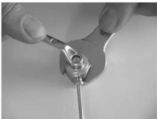
8.2 Replacing injectors

CAUTION!
The activities must be done by authorised personnel. After this operation, we decline all liability resulting from the intervention.
The injector holder must be blocked (with the use of a tool) when removing and mounting the injectors (Fig. 7, page 7).
BURNER ∅ INJECTOR (mm) NUMBER PRINTED ON
INJECTOR
GRILL 0.64 64
OVEN 0.52 52
9 Warranty
The statutory warranty period applies. If the product is defective, please contact the local manufacturer in your country (the address is on the back of the instruction manual) or your reference specialised dealer.
For repair and warranty processing, the following documents must be included when sending the appliance:
- a copy of the receipt showing the date of purchase;
- a reason for the claim or a description of the fault.
6 Description technique
RAZRED IN DRŽAVE, KJER JE V UPORABI PLINSKI TLAK
| 13B/P(30) | 30 mbar Butan (G30) |
| AT BE DE DK FI GB NL NO PT SE SI | 30 mbar Propan (G31) |
| 13+ (28-30/37) | 28-30 mbar Butan (G30) |
| BE CH ES FR GB IE IT PT SI | 37 mbar Propan (G31) |
MODEL SKUPNA NOMINALNA
TOPLOTNA MOČ
POTREBNA KOLIČINA
ZRAKA ZA ZGOREVANJE
m³/h
kW - g/h
Dometic Australia Pty. Ltd.
1 John Duncan Court
Varsity Lakes QLD 4227
1800212121
+61755076001
Mail: sales@dometic-waeco.com.au
AUSTRIA
Dometic Austria GmbH
Neudorferstraße 108
A-2353 Guntramsdorf
+43 2236 908070
+43 2236 90807060
Mail: info@dometic.at
BENELUX
Dometic Branch Office Belgium
Zincstraat 3
B-1500 Halle
+32 2 3598040
+32 2 3598050
Mail: info@dometic.be
BRAZIL
Dometic DO Brasil LTDA
Avenida Paulista 1754, conj. 111
SP 01310-920 Sao Paulo
+55 11 3251 3352
+551132513362
Dometic Group Asia Pacific
Suites 2207-11 · 22/F · Tower 1
The Gateway · 25 Canton Road,
Tsim Sha Tsui · Kowloon
+852 2 4611386
+852 24665553
Mail: info@waeco.com.hk
HUNGARY
Dometic Zrt. Sales Office
Kerékgyártó u. 5
H-1147 Budapest
+3614684400
+3614684401
Domettic Italy S.r.l.
Via Virgilio, 3
I-47122 Forli (FC)
+390543754901
+39 0543 754983
Mail: vendite@dometic.it
IAPAN
Dometic KK
Maekawa-Shibaura, Bldg. 2
2-13-9 Shibaura Minato-ku
Tokyo 108-0023
+81354453333
+81354453339
Mail: info@dometic.jp
MEXICO
Circuito Médicos No. 6 Local 1
Colonia Ciudad Satélite
CP 53100 Naucalpan de Juárez
Estado de México
+52 55 5374 4108
+52 55 5393 4683
Mail: info@dometic.com.mx
NETHERLANDS
Dometic Benelux B.V.
Ecustraat 3
NL-4879 NP Elten-Leur
+31765029000
+31765029019
Mail: info@dometic.nl
NEW ZEALAND
Dometic New Zealand Ltd.
Unite E, The Gate
373 Neilson Street
Penrose 1, Auckland
+6496221490
+6496221573
Mail: customerservices@dometic.co.nz
NORWAY
Dometic Norway AS
∅sterøyveien 46
N-3232 Sandefjord
+4733428450
+4733428459
Mail: firmapost@dometic.no
POLAND
Dometic Poland Sp. z o.o.
Ul. Puławska 435A
PL-02-801 Warszawa
+48 22 414 3200
+48 22 414 3201
Mail: info@dometic.pl
PORTUGAL
Dometic Spain, S.L.
Komsomolskaya square 6-1
RU-107140 Moscow
+7 495 780 79 39
+7 495 916 56 53
Mail: info@dometic.ru
SINGAPORE
Dometic Pte Ltd
18 Boon Lay Way 06-140 Trade Hub 21
Singapore 609966
+65 6795 3177
+65 6862 6620
Mail: dometic@dometic.com.sg
SLOVAKIA
Dometic Slovakia s.r.o. Sales Office Bratislava
Nádražná 34/A
900 28 Ivánka pri Dunaji
+421 2 45 529 680
Mail: bratislava@dometic.com
SOUTH AFRICA
Dometic (Pty) Ltd.
Regional Office
South Africa & Sub-Saharan Africa
2 Avalon Road
West Lake View Ext 11
Modderfontein 1645
Johannesburg
+27114504978
+27114504976
Mail: info@dometic.co.za
SPAIN
Dometic Spain S.L.
Avda, Sierra del Guadarrama, 16
E-28691 Villanueva de la Cañada
Madrid
+34902111042
+34 900 100 245
Mail: info@dometic.es
SWEDEN
Dometic Scandinavia AB
Gustaf Melins gata 7
Dometic Switzerland AG
Riedackerstrasse 7a
CH-8153 Rümlang
+41448187171
+41 44 8187191
Mail: info@dometic.ch
UNITED ARAB EMIRATES
Dometic Middle East FZCO
P.O.Box 17860
S-D 6, lebel Ali Freezone
Dubai
+97148833858
+97148833868
Mail: info@domelic.ae
UNITED KINGDOM
Dometic UK Ltd.
Dometic House, The Brewery
Blandford St. Mary
Dorset DT119LS
+44 344 626 0133
+443446260143
Mail: customerservices@dometic.co.uk
USA
Dometic RV Division
1120 North Main Street
Elkhart, IN 46515
+1574-264-2131