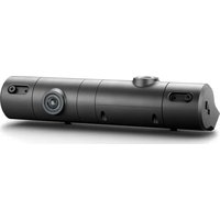
PerfectView CAM 200NAV - Rear Camera DOMETIC - Free user manual and instructions
Find the device manual for free PerfectView CAM 200NAV DOMETIC in PDF.


User questions about PerfectView CAM 200NAV DOMETIC
0 question about this device. Answer the ones you know or ask your own.
Ask a new question about this device
Download the instructions for your Rear Camera in PDF format for free! Find your manual PerfectView CAM 200NAV - DOMETIC and take your electronic device back in hand. On this page are published all the documents necessary for the use of your device. PerfectView CAM 200NAV by DOMETIC.
USER MANUAL PerfectView CAM 200NAV DOMETIC
natural_image
Product photo of a handheld electronic device with coiled cable, connectors, and connector pin (no visible text or symbols)CAM200
EN
Rear View Video Camera
Installation and Operating Manual ..... 13
DE
Rückfahrvideokamera
© 2021 Dometic Group. The visual appearance of the contents of this manual is protected by copyright and design law. The underlying technical design and the products contained herein may be protected by design, patent or be patent pending. The trademarks mentioned in this manual belong to Dometic Sweden AB. All rights are reserved.
1
text_image
2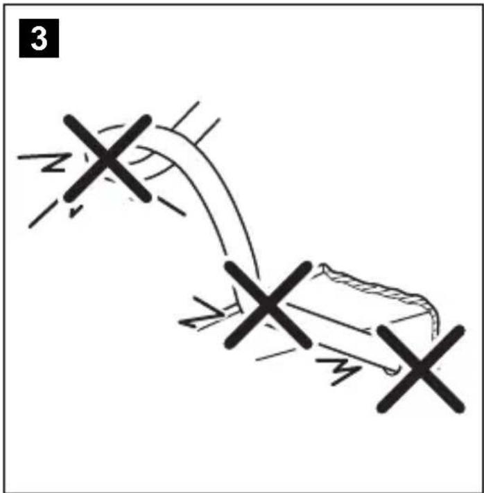
text_image
3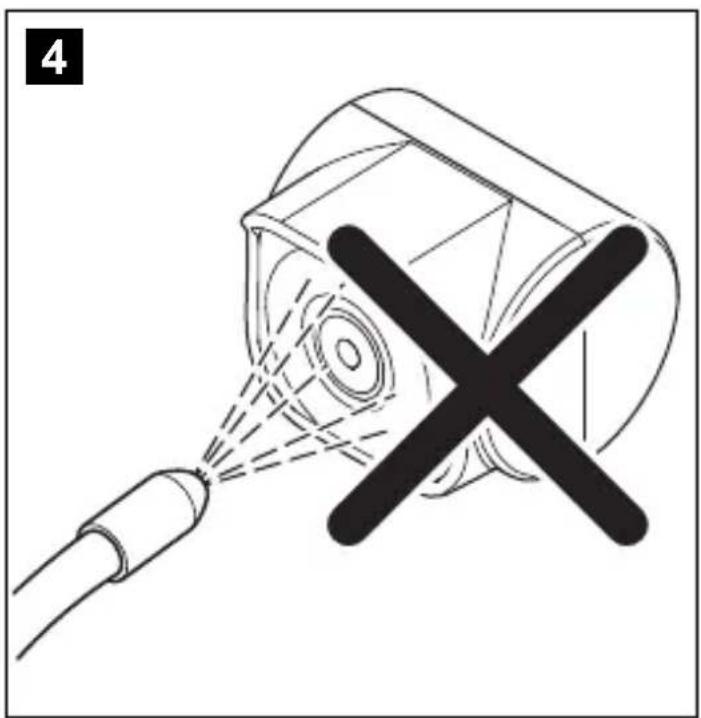
natural_image
Diagram showing a spray gun emitting particles from a nozzle, with no text or symbols present.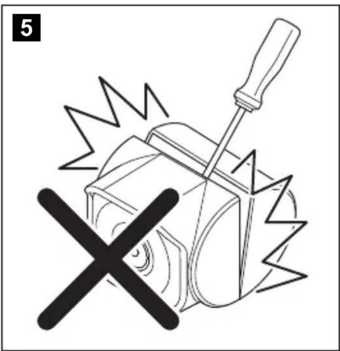
natural_image
Illustration of a hammer and screwdriver crossed over a gear with a cross symbol (no text or labels)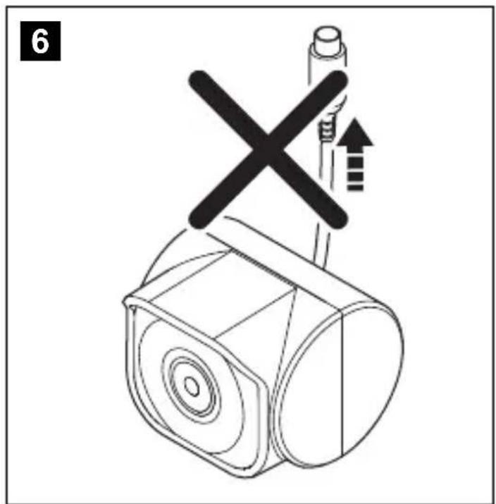
text_image
6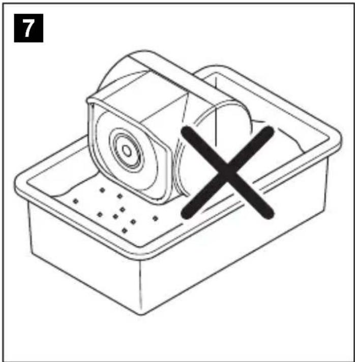
natural_image
Line drawing of a tray with a lid and a cross mark, no text or symbols present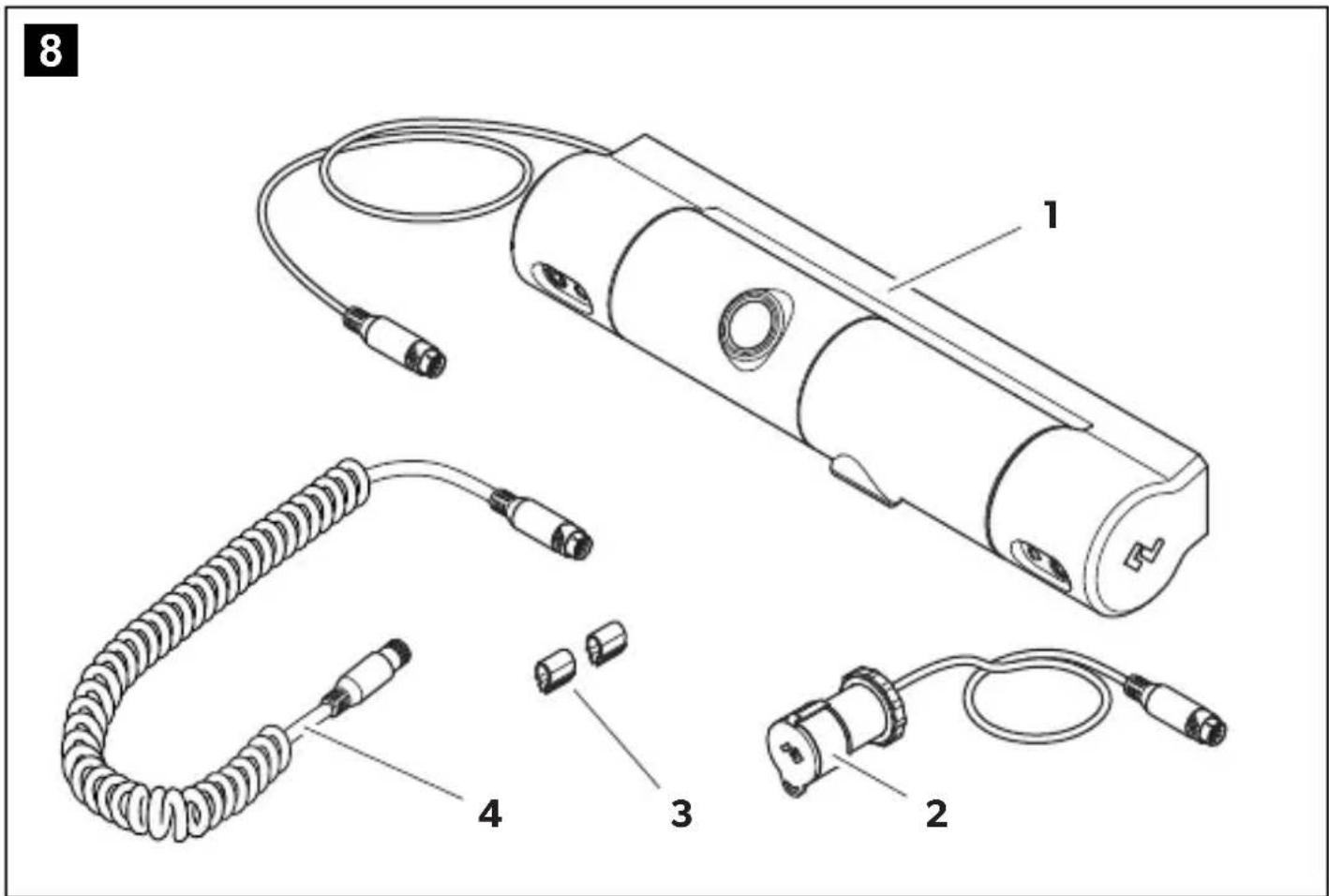
text_image
8 1 4 3 2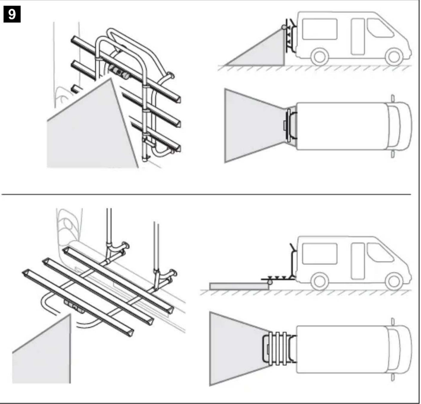
10
natural_image
Pure electrical circuit lines without any symbols11
natural_image
Technical line drawing of a mechanical assembly with pipes and a central rod (no text or symbols)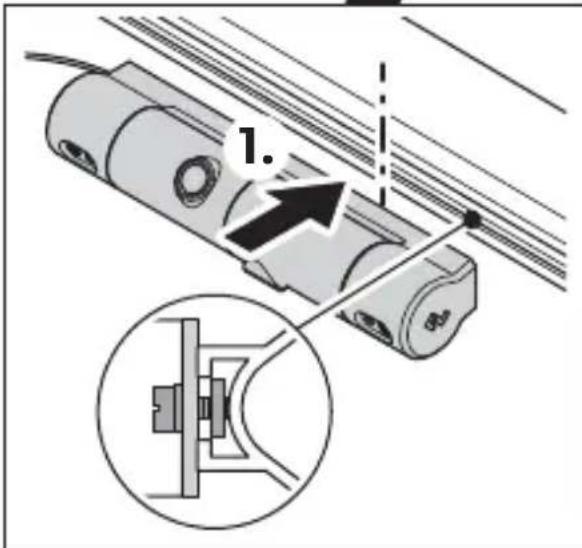
text_image
1.
text_image
2.
text_image
6-8 mm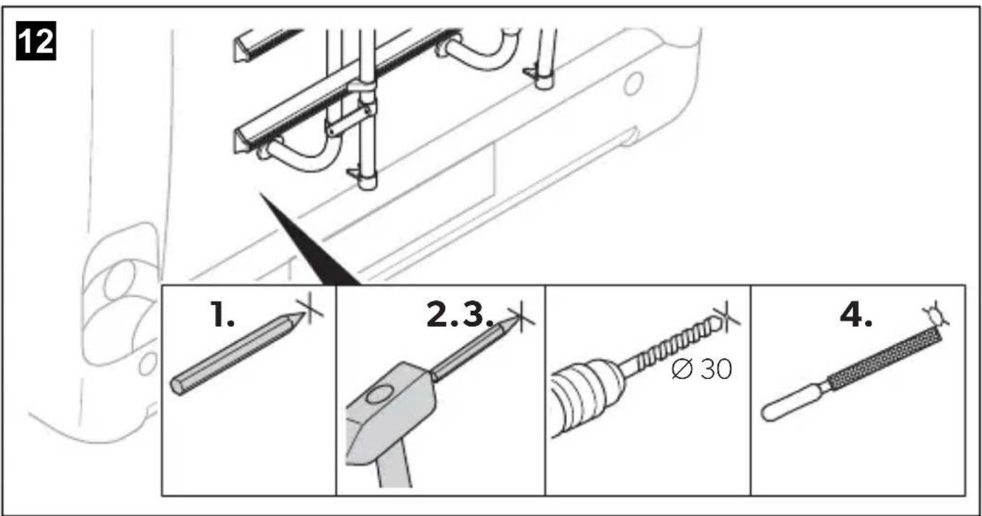
text_image
12 1. 2.3. Ø 30 4.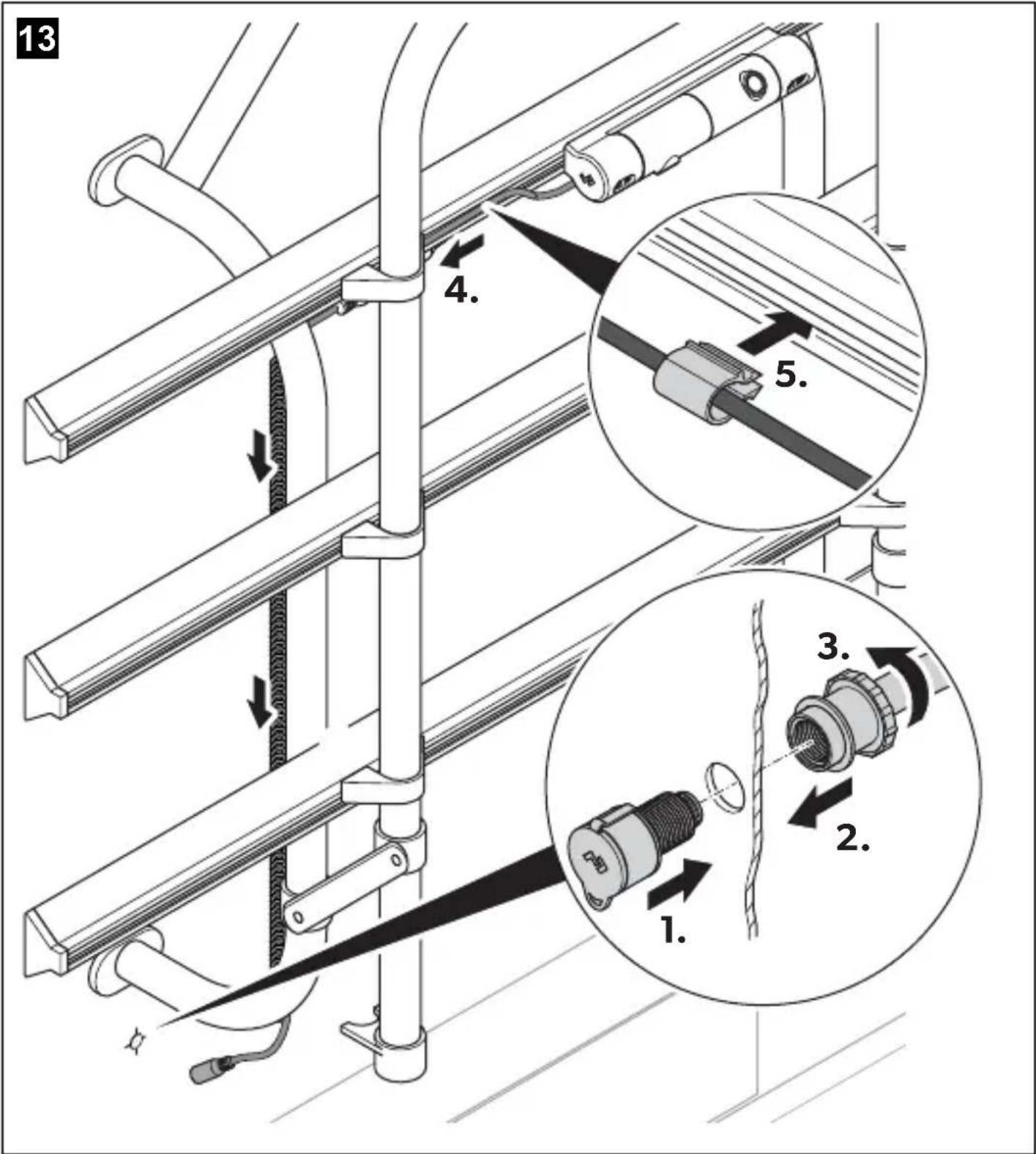
text_image
13 4. 5. 3. 2. 1.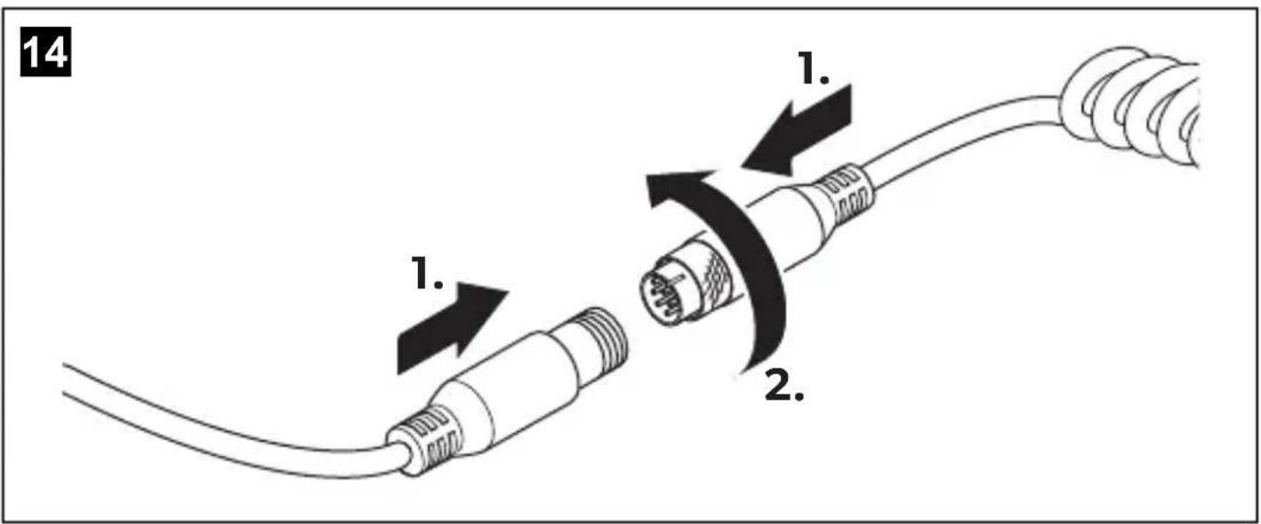
text_image
14 1. 2.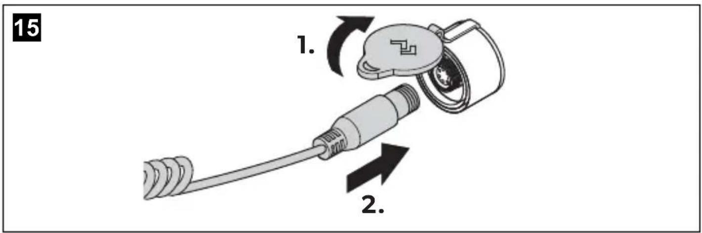
text_image
15 1. 2.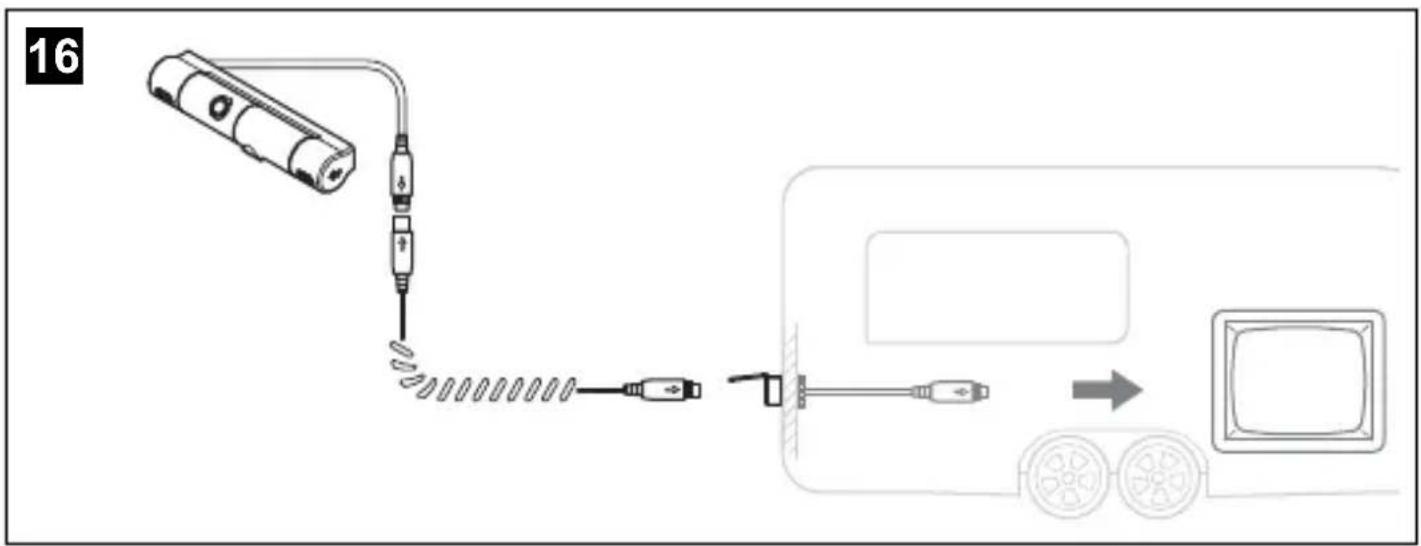
text_image
16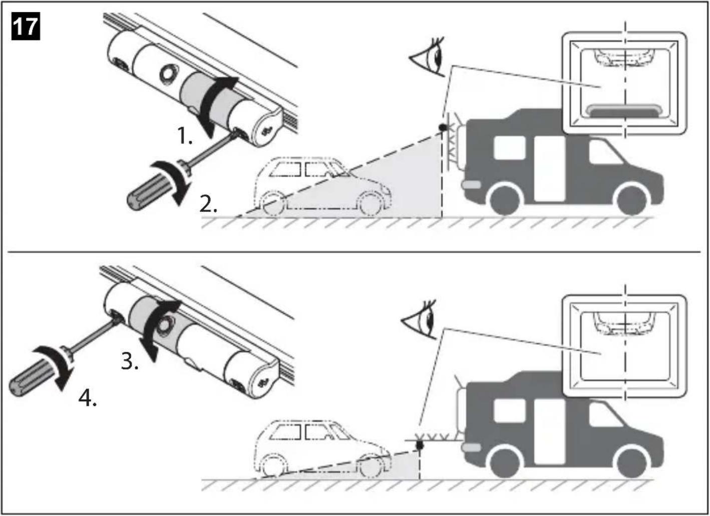
Please read these instructions carefully and follow all instructions, guidelines, and warnings included in this product manual in order to ensure that you install, use, and maintain the product properly at all times. These instructions MUST stay with this product.
By using the product, you hereby confirm that you have read all instructions, guidelines, and warnings carefully and that you understand and agree to abide by the terms and conditions as set forth herein. You agree to use this product only for the intended purpose and application and in accordance with the instructions, guidelines, and warnings as set forth in this product manual as well as in accordance with all applicable laws and regulations. A failure to read and follow the instructions and warnings set forth herein may result in an injury to yourself and others, damage to your product or damage to other property in the vicinity. This product manual, including the instructions, guidelines, and warnings, and related documentation, may be subject to changes and updates. For up-to-date product information, please visit dometic.com.
Contents
1 Explanation of symbols.... 13
2 Safety and installation instructions....14
3 Scope of delivery 16
4 Intended use....16
5 Technical description....17
6 Information on the electrical connections....17
7 Mounting the camera....18
8 Cleaning and caring for the camera....19
9 Warranty 19
10 Disposal....19
11 Technical data....20
1 Explanation of symbols

WARNING!
Safety instruction: Indicates a hazardous situation that, if not avoided, could result in death or serious injury.

CAUTION!
Safety instruction: Indicates a hazardous situation that, if not avoided, could result in minor or moderate injury.

NOTICE!
Indicates a situation that, if not avoided, can result in property damage.

NOTE
Supplementary information for operating the product.
2 Safety and installation instructions
The manufacturer accepts no liability for damage in the following cases:
- Faulty assembly or connection
- Damage to the product resulting from mechanical influences and incorrect connection voltage
• Alterations to the product without express permission from the manufacturer - Use for purposes other than those described in the operating man
Please observe the prescribed safety instructions and stipulations from the vehicle manufacturer and service workshops.

WARNING!
Inadequate supply cable connections could result in short circuits, which could have as a consequence that:
- Cable fires occur
• The airbag is triggered
• Electronic control devices are damaged
• Electric functions fail (indicators, brake light, horn, ignition, lights)

NOTICE!
To prevent the risk of short circuits, always disconnect the negative terminal of the vehicle's electrical system before working on it.
If the vehicle has an additional battery, its negative terminal should also be disconnected.
Please observe the following instructions:
- When working on the following cables, only use insulated cable lugs, plugs and flat push-on receptacles:
- 30 (direct supply from positive battery terminal)
- 15 (connected positive terminal, behind the battery)
- 31 (return line from the battery, earth)
- L (indicator lights left)
-
R (indicator lights right)
Do not use terminal strips. -
Use a crimping tool to connect the cables.
- When connecting to cable 31 (earth), screw the cable
- to the vehicle's earth bolt with a cable lug and a gear disc or
- to the sheet-metal bodywork with a cable lug and a self-tapping screw.
Ensure that there is a good earth connection.
If you disconnect the negative terminal of the battery, all data stored in the volatile memories will be lost.
- The following data must be set again, depending on the vehicle equipment options:
- Radio code
- Vehicle clock
- Timer
- On-board computer
- Seat position
You can find instructions for making these settings in the appropriate operating instructions.
Observe the following installation instructions:

CAUTION!
- Secure the parts installed in the vehicle in such a way that they cannot become loose under any circumstances (sudden braking, accidents) and cause injuries to the occupants of the vehicle.
- Secure any parts of the system covered by the bodywork in such a manner that they cannot be come loose or damage other parts and cables or impair vehicle functions (steering, pedals, etc).
- Always follow the safety instructions of the vehicle manufacturer. Some work (e.g. on retention systems such as the AIRBAG etc.) may only be performed by qualified specialists.

NOTICE!
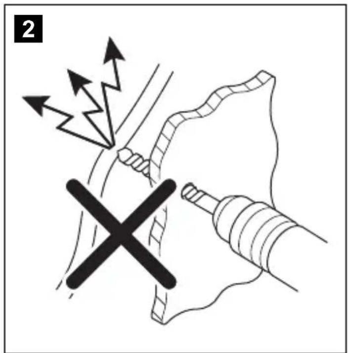
- To prevent damage when drilling, make sure there is sufficient space on the other side for the drill head to come out.
- Deburr all drill holes and treat them with a rust-protection agent.
Observe the following instructions when working with electrical parts:

NOTICE!
- When testing the voltage in electrical cables, only use a diode test lamp or a voltmeter.
Test lamps with an illuminant take up voltages which are too high and which can damage the vehicle's electronic system.
- When making electrical connections, ensure that:
– they are not kinked or twisted
– they do not rub on edges
– they are not laid in sharp edged ducts without protection.
• Insulate all connections.
- Secure the cables against mechanical wear with cable binders or insulating tape, for example to existing cables.
The camera is watertight. However, the sealings on the camera cannot withstand a high-pressure cleaner (fig. 4, page 4).
Observe also the following instructions:
- Do not open the camera, as this impairs the sealing and the function of the camera (fig. 5, page 4).
- Do not pull at the cables, as this impairs the sealing and the function of the camera (fig. 6, page 5).
- The camera is not suitable for submerged operation (fig. 7, page 5).
3 S c o p e o f d e l
No. in fig. 8, Quantity Description Ref. no. page 5
11 Camera CAM200 9600049683
21 Connector grommet CAB25 9600027073
3 2 Cable clip
41 Spiral cable 9600026478
- 1 Installation and Operating Manual
4 l n t e n d e d u s
The camera CAM 200 is a rear view video camera for use on bike racks.
The camera can be used to observe the space around the vehicle from the driver's seat when manoeuvring or parking, for example.

WARNING!
Risk of injury!
Since rear view systems are designed merely as an additional aid for reversing, it does not relieve you of the duty to take proper care when reversing.
This product is only suitable for the intended purpose and application in accordance with these instructions.
This manual provides information that is necessary for proper installation and/or operation of the product. Poor installation and/or improper operating or maintenance will result in unsatisfactory performance and a possible failure.
The manufacturer accepts no liability for any injury or damage to the product resulting from:
- Incorrect assembly or connection, including excess voltage
- Incorrect maintenance or use of spare parts other than original spare parts provided by the manufacturer
• Alterations to the product without express permission from the manufacturer - Use for purposes other than those described in this manual
Dometic reserves the right to change product appearance and product specifications.
5 Technical description
The camera, which is encased in plastic housing, transmits the image to a monitor via a cable.
The camera is mounted under the profile of the bike rack and provides a free view with a loaded bike rack.
Two automatically operating camera modules provide the image with the bike rack folded up or down (fig. 9, page 6).
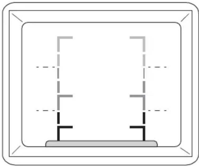
Three distance lines (green, yellow, and red) are displayed (fig. 10, page 7).
6 Information on the electrical connections
6.1 Laying cables

NOTICE! Risk of damage!
- To prevent damage, when drilling ensure that there is sufficient space on the other side for the drill head to come out.
- Cables and connections which are not properly installed will cause malfunctions or damage to components. Correct installation of cables and connections is the basic prerequisite for lasting and trouble-free operation of the retrofitted components.
- The cables may not be exposed for long periods to solvents such as benzine, as the solvents can damage the cable.
Please observe the following instructions:
- As far as possible, use original openings or alternative openings for the connecting cable duct, e.g. the paneling edges, ventilation grilles or blank panels. If no openings are available, you must drill holes for the cables. Check beforehand that there is sufficient room for the drill head to come out on the other side.
- Wherever possible lay cables inside the vehicle, as they are better protected inside than outside the vehicle. If you do need to lay a cable outside the vehicle, ensure that it is well secured (use additional cable ties, insulating tape, etc.).
- To prevent damage to the cables, when laying them ensure that there is sufficient distance to hot or moving vehicle components (exhaust pipes, drive shafts, light systems, fans, heater etc.). Use corrugated piping or other protective materials to protect against mechanical wear.
- Screw on the plug connection of the connecting cables to protect against water penetration (fig. 14, page 11).
- When laying electric connections, ensure that
– They are not kinked or twisted
– They do not rub on edges
- They are not laid in sharp edged ducts without protection (fig. 3, page 4)
- Attach the cables securely in the vehicles to prevent tripping hazards. Use cable binders, insulating tape or glue the cables in place.
- Protect every through-hole made in the bodywork against water penetration, e.g. by using a cable with a sealant and by spraying the cable and the cable sleeve with sealant.

NOTE
Do not start sealing the through-holes until all installation work has been finished for the camera, and the required cable lengths have been established.
7 Mounting the camera
7.1 Tools required
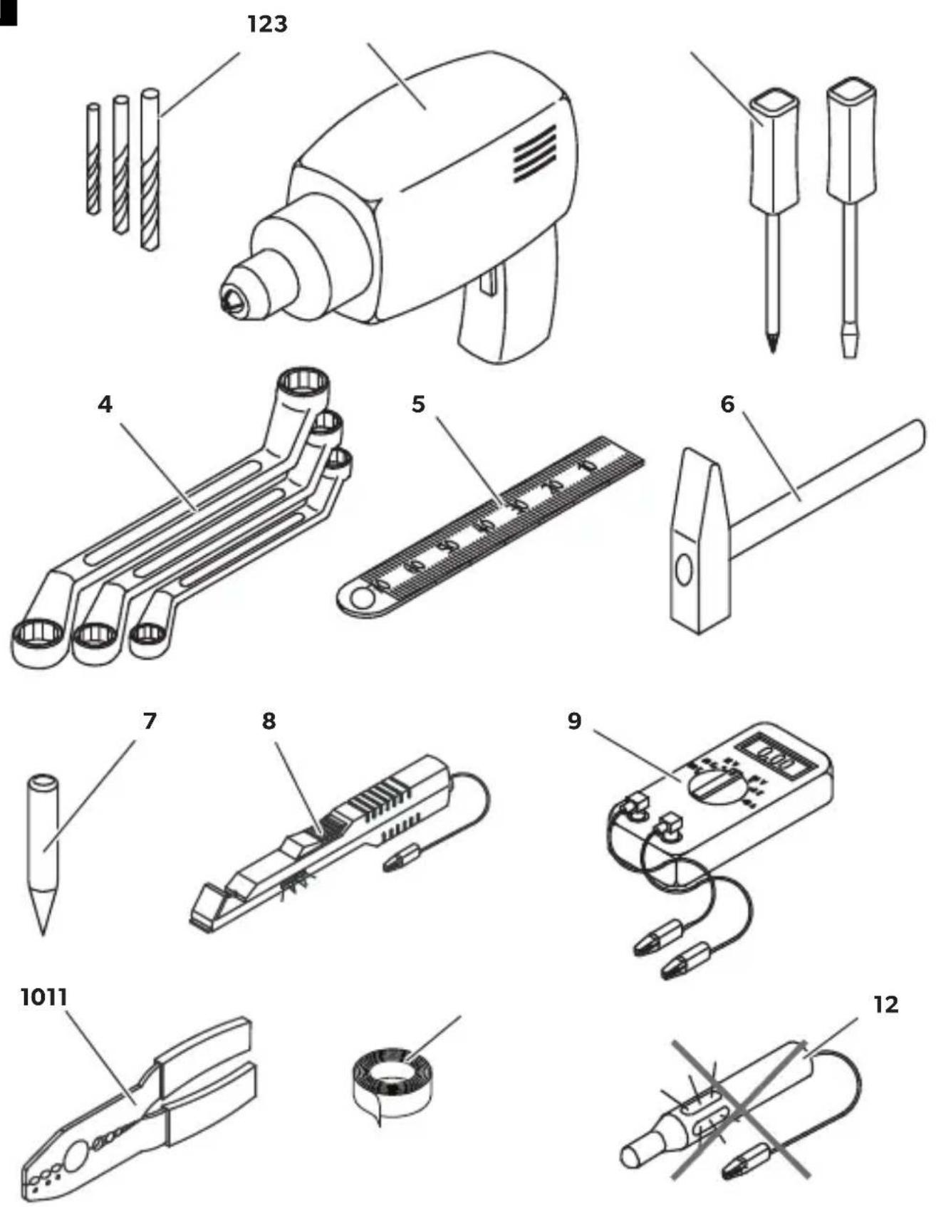
For installation and assembly you will require the following tools:
- Drill bit set (fig. 1 1, page 3)
- Drill (fig. 1 2, page 3)
- Screwdriver (fig. 1 3, page 3)
- Set of ring or open-ended spanners (fig. 1 4, page 3)
• Measuring ruler (fig. 1 5, page 3) - Hammer (fig. 1 6, page 3)
• Centre punch (fig. 1 7, page 3)
To make and test the electrical connection, the following tools are required:
• Diode test lamp (fig. 1 8, page 3) or voltmeter (fig. 1 9, page 3)
• Crimping tool (fig. 1 10, page 3)
• Insulating tape (fig. 1 11, page 3)
- Cable bushing sleeves, if necessary
To fasten the cables you may require additional cable binders.
7.2 Mounting and connecting the camera
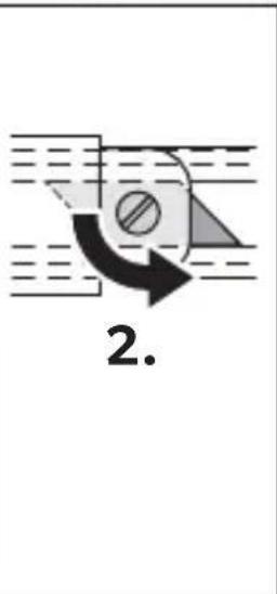
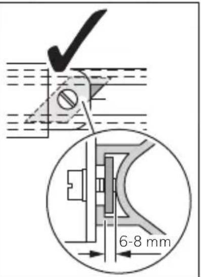
Proceed as shown (fig. 11, page 8 to fig. 16, page 11).

NOTICE! Risk of damage!
Ensure that there is sufficient space on the other side for the drill head to come out

NOTE
To minimise corrosion in the plug, apply a small amount of grease – such as pin grease – inside the plug.
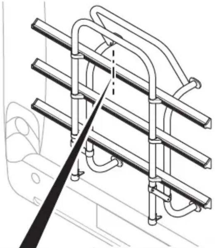
Aligning the camera
▶ Use the monitor image to align the camera (fig. 17, page 12).
▶ Use the monitor image to check the function of the camera.
8 Cleaning and caring for the camera

NOTICE! Risk of damage!
Do not use sharp or hard objects to clean the device as these may damage the device.
▶ Clean the camera with a soft, damp cloth from time to time.
9 W a r r a n t y
The statutory warranty period applies. If the product is defective, please contact your retailer or the manufacturer's branch in your country (see dometic.com/dealer).
For repair and warranty processing, please include the following documents when you send in the product:
• A copy of the receipt with purchasing date
- A reason for the claim or description of the fault
10 Disposal
▶ Place the packaging material in the appropriate recycling waste bins, wherever possible.
If you wish to finally dispose of the product, ask your local recycling center or specialist dealer for details about how to do this in accordance with the applicable disposal regulations.
11 Technical data
| PerfectView CAM200 | |
| Ref. no: 9600049683 | |
| Image sensor: 1/4" CMOS | |
| Pixels: approx. 307000 pixels | |
| Video standard: NTSC | |
| Light sensitivity: 0,1 Lux | |
| Operating voltage: | 10 - 16 V--- |
| Power consumption: 1 W | |
| Protection class: IP69 | |
| Operating temperature: -30 °C to 70 °C | |
| Dimensions W x H x D: | 165 x 35 x 42 mm |
| Weight: | 250 g |
Approval
The device has the E24 approval.

5 Description technique
dometic.com/sales-offices


