PCSA-CXA55 - Camera SONY - Free user manual and instructions
Find the device manual for free PCSA-CXA55 SONY in PDF.

User questions about PCSA-CXA55 SONY
0 question about this device. Answer the ones you know or ask your own.
Ask a new question about this device
Download the instructions for your Camera in PDF format for free! Find your manual PCSA-CXA55 - SONY and take your electronic device back in hand. On this page are published all the documents necessary for the use of your device. PCSA-CXA55 by SONY.
USER MANUAL PCSA-CXA55 SONY
For Customer in China
Operating Instructions GB
Mode d'emploi FR
Printed on recycled paper.
お問い合わせは
Sony Corporation Printed in Japan
© 2011 Sony Corporation
安全のために
text_image
Technical diagram of a mechanical device with numbered components for identification後面

text_image
Technical diagram of a mechanical device with numbered components labeled 7 and 8上面
natural_image
Technical line drawing of a mechanical device with no visible text or symbols①レンズ
デジタル 3 倍ズームレンズです。
②マイク
natural_image
Technical line drawing of a mechanical linkage system with a circular component inserted (no text or symbols)付属のシール
3本機を吸盤で固定する。
natural_image
Diagram of a device with two circular ports and a scroll, showing a control panel and directional arrow (no text or symbols)Before operating the unit, please read this manual thoroughly and retain it for future reference.
Owner's Record
The model and serial numbers are located on the rear side. Record these numbers in the spaces provided below.
Refer to these numbers whenever you call upon your Sony dealer regarding this product.
Model No. PCSA-CXA55
Serial No. ____
WARNING
To reduce the risk of fire or electric shock, do not expose this apparatus to rain or moisture.
To avoid electrical shock, do not open the cabinet. Refer servicing to qualified personnel only.
NOTICE:
This Camera Unit is an accessory and to be used exclusively with PCS-XG80/XG80S/XG55/XG55S/XA80/XA55 HD Visual Communication System.
IMPORTANT
The nameplate is located on the rear side.
For customers in the U.S.A.
This device complies with Part 15 of the FCC Rules.
Operation is subject to the following two conditions: (1) This device may not cause harmful interference, and (2) this device must accept any interference received, including interference that may cause undesired operation.
This equipment has been tested and found to comply with the limits for a Class A digital device, pursuant to Part 15 of the FCC Rules. These limits are designed to provide reasonable protection against harmful interference when the equipment is operated in a commercial environment. This
equipment generates, uses, and can radiate radio frequency energy and, if not installed and used in accordance with the instruction manual, may cause harmful interference to radio communications. Operation of this equipment in a residential area is likely to cause harmful interference in which case the user will be required to correct the interference at his own expense.
You are cautioned that any changes or modifications not expressly approved in this manual could void your authority to operate this equipment.
For the customers in Canada
This Class A digital apparatus complies with Canadian ICES-003.
For the customers in Europe
The manufacturer of this product is Sony Corporation, 1-7-1 Konan, Minato-ku, Tokyo, Japan. The Authorized Representative for EMC and product safety is Sony Deutschland GmbH, Hedelfinger Strasse 61, 70327 Stuttgart, Germany. For any service or guarantee matters please refer to the addresses given in separate service or guarantee documents.
For the customers in Europe, Australia and New Zealand
WARNING
This is a Class A product. In a domestic environment, this product may cause radio interference in which case the user may be required to take adequate measures.
In the case that interference should occur, consult your nearest authorized Sony service facility.
This apparatus shall not be used in the residential area.
Table of Contents
Precautions ......18
Phenomena Specific to CMOS Image Sensors ....19
Features 19
Location and Functions of Parts and Controls ....20
Installing the Camera ....21 Mounting the Camera on the TV Monitor ....21
Temporarily Stopping Image Capture ....22
Troubleshooting 23
Specifications ......24
Precautions
Operating or storage location
Operating or storing the camera in the following locations may cause damage to the camera:
- Extremely hot or cold places (Operating temperature: 5^ to 35^ [41°F to 95°F])
- Exposed in direct sunlight, or close to heating equipment (e.g., near heaters)
- Close to sources of strong magnetism
- Close to sources of powerful electromagnetic radiation, such as radios or TV transmitters
- Locations subject to vibration or shock
Ventilation
To prevent heat buildup, do not block air circulation around the camera.
Connecting to the Communication System
Do not connect the camera cable to the HD Visual Communication System while the Communication System is turned on. Otherwise, the camera and System may suffer damage, or the picture may not be displayed.
Transportation
When transporting the camera, repack it as originally packed at the factory or in materials equal in quality.
Cleaning the main unit
- Use a blower to remove dust from the lens.
- When the body of the camera is dirty, clean it with a soft cloth that is soaked with a diluted neutral detergent and tightly wrung. Then finish with a dry cloth.
- Do not use any type of solvents, which may damage the finish.
- When you use a chemical cloth, follow its instructions.
- Do not sprinkle volatile matter such as pesticide over your camera nor allow rubber or vinyl to come in contact with the
camera for a long period of time. Doing so may damage the finish.
Maintenance
The camera mechanism may cause abnormal noise due to wear and lubrication loss after a long period of use. To maintain optimum performance, we recommend periodical maintenance. If abnormal noise occurs, consult with your Sony dealer.
Note on laser beams
Laser beams may damage the CMOS. If you shoot a scene that includes a laser beam, be careful not to let a laser beam become directed into the CMOS of the camera.
Phenomena Specific to CMOS Image Sensors
The following phenomena that may appear in images are specific to CMOS (Complementary Metal Oxide Semiconductor) image sensors. They do not indicate malfunctions.
White flecks
Although the CMOS image sensors are produced with high-precision technologies, fine white flecks may be generated on the screen in rare cases, caused by cosmic rays, etc. This is related to the principle of CMOS image sensors and is not a malfunction.
White flecks tend to be seen particularly in the following cases:
• during operation at a high environmental temperature
- when you have raised the gain (sensitivity)
This phenomena may be improved by turning the camera off and then on again.
Aliasing
When fine patterns, stripes, or lines are shot, they may appear jagged or flicker.
Features
The camera is designed to be used exclusively with the Sony PCS-XG80/XG80S/XG55/XG55S/XA80/XA55 HD Visual Communication System. The power is supplied to the camera by the HD Visual Communication System. For adjustments and settings of the camera, refer to the Operating Instructions of the PCS-XG80/XG80S/XG55/XG55S/XA80/XA55.
CMOS camera with high image quality
The camera unit incorporates 8,000,000 effective picture elements (pixels) that can shoot high-definition images to offer superior picture quality.
Built-in microphone
With a built-in microphone, the camera leaves a small footprint.
Lens cover for when image capture is not required
Hiding the lens with the lens cover allows you to temporarily stop image capture while leaving the system running.
Simple suction cup mounting
Mount the camera to the TV monitor with a single suction cup. The adjustable link arm allows mounting on a wide range TV monitors. (Mounting may not be possible on some TV monitors.)
Video format compatible with HD
The camera allows you to shoot an image using the 720p high definition video format, which is equivalent to an HD-TV broadcast.
Location and Functions of Parts and Controls
Front
text_image
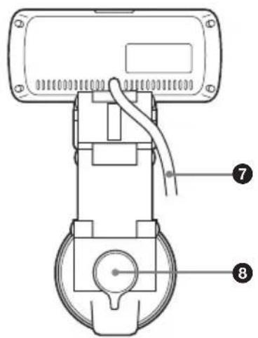
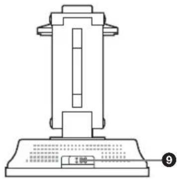
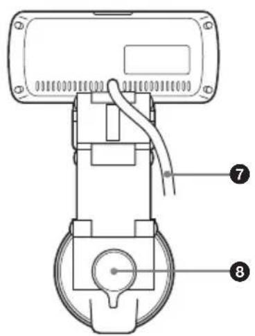
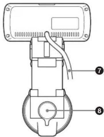
Technical diagram of a mechanical device with numbered components for identificationRear

text_image
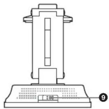
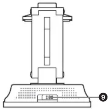
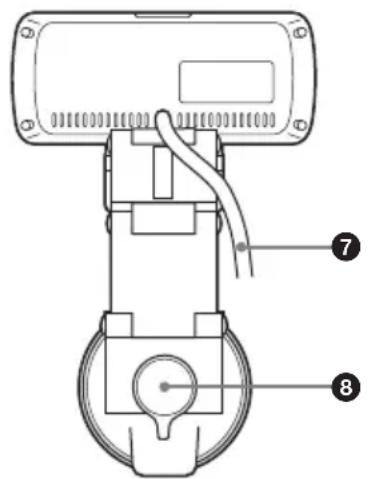
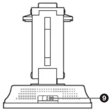
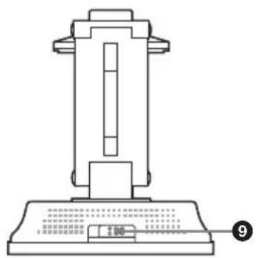
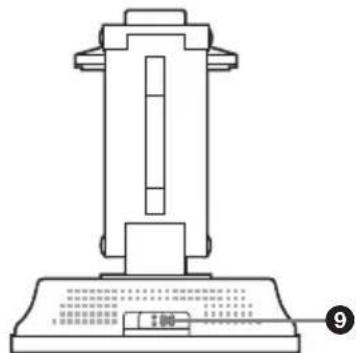
Technical diagram of a mechanical device with numbered annotations pointing to componentsTop
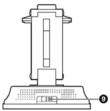
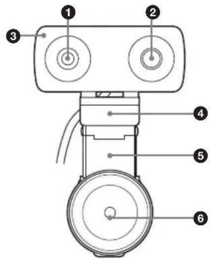
text_image
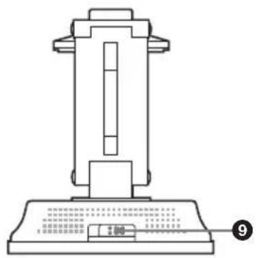
Technical diagram of a mechanical device with labeled components and part number 9① Lens
3× digital zoom lens.
②Microphone
Built-in monaural microphone.
③Tally lamp
Lights when camera images are being sent to the remote party during conferences.
④ Tilt base
Rests on the top of the TV monitor, and supports the camera unit.
⑤Link arm
Adjust this so that the suction cup at the bottom aligns properly to the rear of the TV monitor.
⑥Suction cup
Attaches to the rear of the TV monitor or to a desk.
If the suction cup does not adhere properly, affix the supplied adhesive disc to the rear of the TV monitor or to the desk beforehand.
⑦Connection cable
Connects to the CAMERA connector on the HD Visual Communication System.
⑧Suction cup lever
Turn this lever while pressing down hard on it to attach the suction cup. Simply turn the lever to release the suction cup.
⑨ Lens cover lever
Opens or closes the lens cover.
Installing the Camera
Mounting the Camera on the TV Monitor
Mount this camera unit to the top of the TV monitor.
1 Remove the protective cover from the suction cup.
2 Determine the location to which the suction cup will be attached.
To determine a location for the suction cup, rest the camera unit on the top of the TV monitor, and move the adjustable link arm.
Notes
- Do not tilt the TV monitor 20 degrees or more in the forward or back direction. (This will exceed the camera unit's tilt range ( ± 20 degrees).)
- Depending on the TV monitor model, certain areas may get hot. Avoid these areas when determining a location for mounting.
- Do not obstruct the ventilation holes of the TV monitor when mounting the camera.
- The suction cup may not attach securely on the following types of TV monitors. In such cases, affix the supplied adhesive disc to the TV monitor, and then attach the camera unit to the disc.
If you do not use the adhesive disc, the suction cup may not attach securely, or the TV monitor may be warped or damaged.
- TV monitors made of soft materials that bend to the touch - TV monitors with rough surfaces
- Select the location to affix the adhesive disc carefully.
As the disc is highly adhesive, it cannot be easily removed once it is affixed to the TV monitor. Attempting to remove
the disc with excessive force may warp or damage the TV monitor.
- Wait at least 24 hours for the adhesive disc to fully adhere to the surface before attaching the camera unit to the disc.
- Once removed, the adhesive disc cannot be affixed again, as its adhesive properties are reduced.
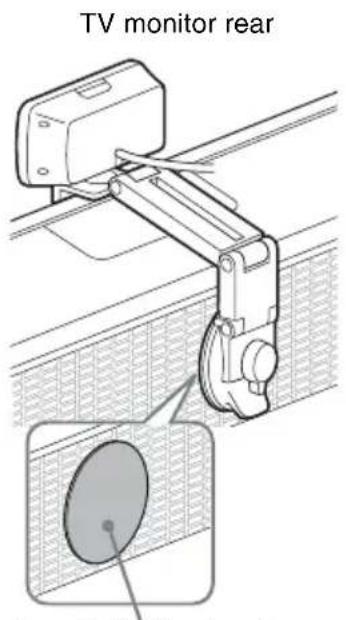
text_image
TV monitor rearSupplied adhesive disc
3 Secure the camera unit to the TV monitor with the suction cup.
While pressing down hard on the center of the suction cup lever, turn it in the direction illustrated (LOCK direction).
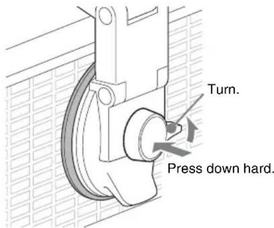
text_image
Turn. Press down hard.Notes
- The camera unit cannot be mounted on ceilings or walls.
- If you do not apply enough pressure when pressing down on the center of the suction cup lever, the suction cup lever may become
unlocked. In such cases, perform the above step for securing the suction cup again.
To release the suction cup
Turn the suction cup lever in the opposite direction (RELEASE direction).
Notes
- Do not forcibly remove the suction cup by inserting your fingers or other objects between the suction cup and the TV monitor. Doing so may damage the suction cup.
- When the camera unit is not mounted, always attach the protective cover to the suction cup. The adhesive strength of the suction cup will decrease if its surface is dirty or scratched.
- If the surface of the suction cup becomes dirty, gently wipe the surface with a soft, non-abrasive cloth that has been moistened with water. In addition, adhere to the following precautions.
- Do not use detergents and other cleaning solutions.
- Make sure that the suction cup is completely dry before attaching it again.
- To prevent damage, do not allow water to enter the inside of the TV monitor.
Temporarily Stopping Image Capture
Slide the lens cover lever to the left (when facing the front of the camera unit).
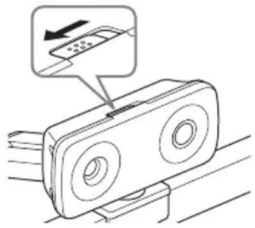
natural_image
Diagram of a device with two circular ports and a scroll, showing a control panel with an arrow pointing to the screen (no text or symbols present)If a conference is conducted with the lens cover closed, only a black screen will be visible to the remote party.
When the lens cover is closed, the Home menu appears as follows.
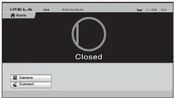
text_image
IPELA Home AAA IP 300, 300, 300, 300 24/1/2006 10:30 Closed Camera ConnectNote
When the power supply to the camera unit is disabled, the Home menu appears as follows.
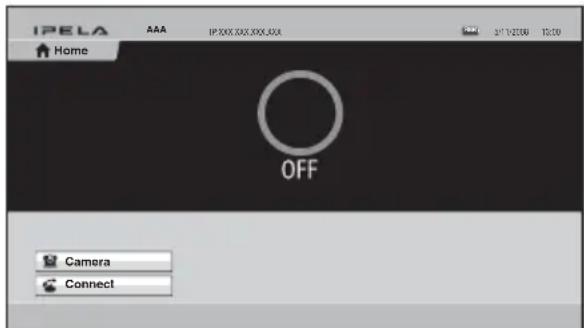
Operate the Remote Commander to restore power supply to the camera unit.
Troubleshooting
Before bringing in your camera for service, check the following as a guide to troubleshooting the problem. If the problem cannot be corrected, consult with your Sony dealer.
| SymptomCauseRemedy | ||
| The power of the camera is not turned on. | The camera cable is not inserted firmly to the CAMERA connector on the HD Visual Communication System. | Insert the camera cable firmly into the CAMERA connector on the Communication System. |
| The HD Visual Communication System cannot control the camera correctly. | — Turn off the power of the Communication System, and turn it on again after a while. | |
Specifications
Video signal 720p/30
Synchronization
Internal synchronization
Image device 1/3.2 type (5.7 mm), CMOS
Approx. 8,000,000 pixels
Lens f = 2.94 mm (22 mm in 35 mm equivalent) F2.8
Horizontal angle: 80.1 degrees
Vertical angle: 62.7 degrees
Minimum object distance
80 mm (WIDE end)
Pan/tilt action
Horizontal: ±20 degrees,
Vertical: ±20 degrees, manual operation
Input voltage 19.5 V DC
Power consumption
4 W or less
Operating temperature
5^ to 35^ (41°F to 95°F)
Storage temperature
-20^ to +60^ (-4^ to +140^)
Dimensions 116 × 50 × 225 mm
(4^5/8 × 2 × 8^7/8 inches) (w/h/d)
Mass Approx. 500 g (1 lb 2 oz)
Supplied accessories
Adhesive disc for suction cup (1)
Operating Instructions (1)
Design and specifications are subject to change without notice.
Note
Always verify that the unit is operating properly before use. SONY WILL NOT BE LIABLE FOR DAMAGES OF ANY KIND INCLUDING, BUT NOT LIMITED TO, COMPENSATION OR REIMBURSEMENT ON ACCOUNT OF THE LOSS OF PRESENT OR PROSPECTIVE PROFITS DUE TO FAILURE OF THIS UNIT, EITHER DURING THE WARRANTY PERIOD OR AFTER EXPIRATION OF THE WARRANTY, OR FOR ANY OTHER REASON WHATSOEVER.
Précautions ......28
text_image
Technical diagram of a mechanical device with numbered components for identificationArrière
text_image
Technical diagram of a mechanical device with numbered components labeled 7 and 8Dessus
natural_image
Technical line drawing of a mechanical device with no visible text or symbols①Objectif
natural_image
Diagram of a device with a scroll wheel and a mouse, showing a control panel (no text or symbols present)text_image
Technical diagram of a mechanical device with numbered components for identificationRückseite

text_image
Technical diagram of a mechanical device with numbered annotations pointing to componentsOberseite
natural_image
Technical line drawing of a mechanical device with no visible text or symbols①Objektiv
natural_image
Technical diagram of a mechanical linkage assembly with a magnified inset showing a circular component (no text or symbols present)natural_image
Diagram of a device with two circular ports and an arrow pointing to a control panel (no text or symbols)text_image
Technical diagram of a mechanical device with numbered components for identificationParte posterior

text_image
Technical diagram of a mechanical device with numbered components labeled 7 and 8Parte superior
natural_image
Technical line drawing of a mechanical device with no visible text or symbols①Objetivo
natural_image
Technical diagram of a mechanical linkage system with a circular component inserted into a grid-patterned area (no text or symbols)Disco adhesivo suministrado
natural_image
Diagram of a device with two circular ports and a scroll, showing a control panel and directional arrow (no text or symbols)text_image
Technical diagram of a mechanical device with numbered components for identificationLato posteriore
text_image
Technical diagram of a mechanical device with numbered annotations pointing to componentsParte superiore
text_image
Technical diagram of a mechanical device with labeled components and a scale indicator①Obiettivo
natural_image
Diagram of a device with a scroll and a mouse, showing no text or symbolsDimensioni 116 × 50 × 225 mm (L × H × P)
Peso Circa 500 g
text_image
Technical diagram of a mechanical device with numbered components for identification后面
text_image
Technical diagram of a mechanical device with numbered components labeled 7 and 8顶部
text_image
1.50 2.50 3.50 4.50 5.50 6.50 7.50 8.50 9.50①镜头
3 倍数字变焦镜头。
②麦克风
内置单声道麦克风。
③ 摄像指示灯
natural_image
Technical diagram of a mechanical linkage system with a magnified inset showing a circular component (no text or symbols present)随附的粘着盘
natural_image
Diagram of a remote control device with a scroll and indicator hand (no text or symbols)text_image
Technical diagram of a mechanical device with numbered components for identificationPosterior
text_image
Technical diagram of a mechanical device with numbered components labeled 7 and 8Parte superior
natural_image
Technical line drawing of a mechanical device with no visible text or symbols①Lente
Lentes de zoom digital 3×.
②Microfone
natural_image
Technical diagram of a mechanical linkage assembly with a magnified inset showing a circular component (no text or symbols present)natural_image
Diagram of a device with two circular ports and a scroll, showing a control panel with an arrow pointing to it (no text or symbols present)text_image
IPELA AAA Início Closed Câmera ConectarNota
text_image
IPELA AAA Início OFF Câmera ConectarHorizontal: ±20 graus,