
CBK-3621XS - Camera SONY - Free user manual and instructions
Find the device manual for free CBK-3621XS SONY in PDF.

| Product Type | Camera Imager Extension Kit |
| Brand and Model | Sony CBK-3621XS |
| Camera Head Weight | Approx. 0.54 kg (1 lb 3.0 oz) |
| Head Weight with PL Mount Adapter | Approx. 1.05 kg (2 lb 5.0 oz) |
| Weight of Detachable Cable (4.5 m) | Approx. 0.86 kg (1 lb 14.3 oz) |
| Body Adapter Weight | Approx. 0.36 kg (12.7 oz) |
| Power Consumption | Approx. 15 W max (5.5K 2.39:1 120 FPS) |
| Operating Temperature | 0 °C to 40 °C (32 °F to 104 °F) |
| Storage Temperature | -20 °C to +60 °C (-4 °F to +140 °F) |
| Maximum Extension | Up to 12 m (39.4 ft) with CBK-12C3621 option |
| Compatible ND Filters | 9 interchangeable filters: Clear, 0.3, 0.6, 0.9, 1.2, 1.5, 1.8, 2.1, 2.4 |
| Lens Mount | PL mount and E mount (Cooke /i compatible) |
| Image Sensor | 8.6K CMOS (same as MPC-3628) |
| Input/Output Connectors | 24 V IN (Fischer 3-pin), 24 V OUT (Fischer 3-pin), LENS META IN (LEMO 4-pin) |
| External Power | 24 V DC via 24 V IN connector; 24 V output for lens servo |
| Lens Metadata Input | Cooke/i protocol, RS-232C |
| Detachable Cable Length | 4.5 m (14.8 ft) standard |
| Maintenance and Cleaning | Soft dry cloth; do not use alcohol or solvents; for ND filters: soft brush or blower |
| Fan Lifespan | Approx. 5 years (8h/day, 25 days/month) – consumable part |
| ND Switch Lifespan | Approx. 5 years |
| Safety | Class 1 laser product (IEC 60825-1:2014); do not use in domestic environment |
| Supplied Accessories | 9 ND filters, shims (circular and third-circle), PL and E lens caps, screws, instruction manual, warranty |
| Camera Compatibility | MPC-3628/MPC-3626 (software V4.0 or later) |
Frequently Asked Questions - CBK-3621XS SONY
User questions about CBK-3621XS SONY
0 question about this device. Answer the ones you know or ask your own.
Ask a new question about this device
Download the instructions for your Camera in PDF format for free! Find your manual CBK-3621XS - SONY and take your electronic device back in hand. On this page are published all the documents necessary for the use of your device. CBK-3621XS by SONY.
USER MANUAL CBK-3621XS SONY
Operating Instructions ____ EN
Mode d'emploi FR
© 2025 Sony Corporation
5068759010
安全のために
短いネジ
natural_image
Technical illustration of a mechanical assembly showing a connector with pins and a separate housing (no text or symbols present)ご注意
natural_image
Technical line drawing of a mechanical assembly with two views of a housing (no text or symbols present)PLマウントアダプターを取り付けるには
natural_image
Technical line drawing of a mechanical assembly with two views of a housing (no text or symbols present)PLマウントレンズを取り付ける
natural_image
Technical line drawing of a mechanical assembly with a cylindrical component and a flanged housing (no text or symbols)ご注意
natural_image
Technical line drawing of a camera lens assembly showing a side view and top view (no text or symbols)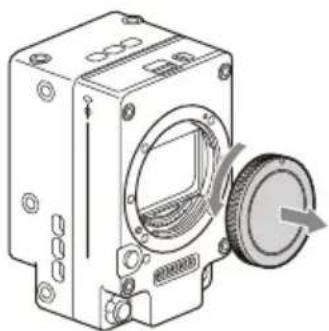
natural_image
Technical line drawing of a mechanical device with a circular housing and a rotating knob (no text or symbols)natural_image
Technical line drawing of a mechanical device with a close-up view of its cylindrical component (no text or symbols present)マウント標点(白色)
ご注意
natural_image
Technical line drawing of a mechanical component with mounting holes and central square aperture (no text or symbols)円弧型のシムを使用する場合
刻印がある面を表にして取り付けます。
NDフィルターを取り出す
ご注意
ご注意
Before operating the unit, please read this manual thoroughly and retain it for future reference.
FOR CUSTOMERS IN CANADA (INCLUDING IN THE PROVINCE OF QUEBEC) ALL INSTRUCTIONS AND STATEMENTS WHICH ARE NECESSARY FOR CANADIAN CUSTOMERS ARE PROVIDED IN ENGLISH AND FRENCH. OTHER INSTRUCTIONS AND STATEMENTS NOT PROVIDED IN ENGLISH AND FRENCH ARE NOT FOR CANADIAN CUSTOMERS (INCLUDING IN THE PROVINCE OF QUEBEC).
This equipment is not suitable for use in locations where children are likely to be present.

This symbol means "Caution: Please refer for further information to the user manual."
Caution
This product has been tested and found compliant with the limits set out in the EMC regulation when using connection cables shorter than 3 meters for the following port(s):
- 24 V OUT
- LENS META IN
For the customers in the U.S.A.
This equipment has been tested and found to comply with the limits for a Class A digital device, pursuant to part 15 of the FCC Rules. These limits are designed to provide reasonable protection against harmful interference when the equipment is operated in a commercial environment. This equipment generates, uses and can radiate radio frequency energy and, if not installed and used in accordance with the instruction manual, may cause harmful interference to radio communications. Operation of this equipment in a residential area is likely to cause harmful interference in which case the user will be required to correct the interference at his own expense.
You are cautioned that any changes or modifications not expressly approved in this manual could void your authority to operate this equipment.
If you have any questions about this product, you may call:
Sony Customer Information Service Center 1-800-222-7669 or http://www.sony.com/
Supplier's Declaration of Conformity
Trade Name : SONY
Model : CBK-3621XS
Responsible party : Sony Electronics Inc.
Address : 16535 Via
Esprillo, San
Diego, CA 92127
U.S.A.
Telephone : 858-942-2230 Number
This device complies with part 15 of the FCC Rules. Operation is subject to the following two conditions: (1) This device may not cause harmful interference, and (2) this device must accept any interference received, including interference that may cause undesired operation.
For the customers in Canada
CAN ICES-3 (A)/NMB-3(A)
WARNING
Operation of this equipment in a residential environment could cause radio interference.
Not intended for use in residential environments.
ATTENTION
The electromagnetic fields at the specific frequencies may influence the picture and sound of this unit.
For the customers in Europe
This apparatus shall not be used in the residential area.
Information for CU LI TR Product name: Filter Case
Model name: FILTER CASE_A
Country or region of manufacturing: Vietnam
Material: polyester/synthetic leather
Caution
Use of controls or adjustments or performance of procedures other than those specified herein may result in hazardous radiation exposure.
Caution
The use of optical instruments with this product will increase eye hazard.
IEC 60825-1:2014
CLASS 1 LASER
PRODUCT
The distributor in Canada:
Sony of Canada ULC
2235 Sheppard Avenue East, Suite 700, Toronto, Ontario M2J 5B5, Canada
주의
Reduction in the Use of Hazardous Substances in Electrical & Electronic Equipment (Applicable in Republic of India)
This product and its components, consumables, parts or spares comply with the hazardous substances restriction of India's E-Waste (Management) Rules. The maximum allowable concentrations of the restricted substances are 0.1% by weight in homogenous materials for Lead, Mercury, Hexavalent Chromium, Polybrominated Biphenyls (PBB) and Polybrominated Diphenyl Ethers (PBDE), and 0.01% by weight in homogenous materials for Cadmium, except for the exemptions specified in Schedule II of the aforesaid Rules.
For the customers in the U.S.A.
SONY LIMITED WARRANTY- Please visit www.sony.com/psa/warranty for important information and complete terms and conditions of Sony's limited warranty applicable to this product.
For the customers in Canada
SONY LIMITED WARRANTY - Please visit www.sony.com/psa/warranty for important information and complete terms and conditions of Sony's limited warranty applicable to this product.
For the customers in Europe
Sony Europe B.V. - Standard Warranty and Exceptions on Standard Warranty. Please visit https://pro.sony/support-services/primesupport/support-professional-solutions-europe-standard-product-warranty for important information and complete terms and conditions.
For the customers in Korea
SONY LIMITED WARRANTY - Please visit https://pro.sony/ko_KR/support-services for important information and complete terms and conditions of Sony's limited warranty applicable to this product.
WARNING CAUTION
Failure to follow these precautions may result in death or serious injury due to fire or electric shock.
- Shooting without being aware of your surroundings may result in accidents or injuries.
- Do not record or play video while driving a car or motorcycle. This may cause traffic accidents.
- Water or foreign objects entering the unit may cause a fire, electric shock, or injury. If water or foreign objects enter the unit, immediately turn off the unit, remove the power cord and connection cords, and contact your Sony service or sales representative.
- If the ventilation holes are blocked during use, heat will accumulate inside the unit and may cause a fire or malfunction.
Failure to follow these precautions may result in injury due to electric shock or accidents, or cause damage to surrounding objects.
- Installing the unit in locations, such as those above, may result in fire or electric shock.
- Placing the unit on an unstable surface, such as a wobbly stand, may cause the unit to fall and result in injury.
- Do not insert any metallic objects into the connectors (connection terminals). Doing so may cause a short-circuit between pins and result in a fire or malfunction.
- Insert connectors straight in when connecting cables. Inserting connectors at an angle may cause a short-circuit between pins and result in a fire or malfunction.
- If a connector has a locking spring or screw, use it to securely fasten the connector in place. This will prevent poor connection.
- Connect connectors with a ground wire to ground.
- Tripping over the power cord or connection cables may cause the unit to fall and result in injury.
- Mounting the unit using a method other than that specified may cause the unit to fall due to insufficient strength and result in injury.
- Attaching optional devices or parts incorrectly may cause the unit to fall and result in injury. When attaching optional devices or parts, be sure to attach them exactly as described in the manual.
- Stacking two or more units without using a rack may cause the unit to fall and result in injury.
-
If lightning strikes, there is a risk of electric shock. If you hear nearby thunder, immediately stop using the unit and move away from it.
-
Carrying the unit by holding any part other than the handle may cause the unit to fall and result in injury.
- When opening or closing the panel of this unit, be careful not to pinch your fingers. When opening the panel, be sure to properly secure it as described in the manual.
- Disassembling or modifying the unit may cause a fire, electric shock, or injury. For internal inspection or repairs, contact the store where you purchased the unit or your Sony service representative.
- Cleaning the unit while it is connected to the power supply may result in electric shock.
- Storing the unit on an unstable or inclined surface may cause the unit to fall and result in injury.
Usage Precautions
- The camera must be updated to the following software version or later to use this unit.
MPC-3628/MPC-3626: V4.0 or later Disconnect the unit and reassemble the camera to its normal state before updating. - Do not leave the unit in a location exposed to direct sunlight. Sunlight may be focused on nearby objects and cause a fire. If leaving the unit exposed to direct sunlight is unavoidable, always attach the lens cap.
- If the unit is suddenly taken from a cold to a warm location, or if ambient temperature suddenly rises, moisture may form on the outer surface of the unit and/or inside of the unit. This is known as condensation. If condensation occurs, turn off the unit and wait until the condensation clears before operating the unit. Operating the unit while condensation is present may damage the unit.
- The life expectancy of the ND filter detection switch is about 5 years.
- Using the unit with dirt or dust adhering to the connector between the camera body and sensor block may cause a failure or malfunction. When storing, be careful not to let dirt accumulate.
- The fan is a consumable part that will need periodic replacement.
When operating at room temperature, a normal replacement cycle will be about 5 years (8 hours per day; 25 days per month). If usage exceeds the above normal usage frequency, the life expectancy may be reduced correspondingly.
However, this replacement cycle represents only a general guideline and does not imply that the life expectancy of this part is guaranteed. For details on parts replacement, contact your dealer.
To prevent electromagnetic interference from portable communications devices
The use of portable telephones and other communications devices near this unit can result in malfunctions and interference with audio and video signals.
It is recommended that the portable communications devices near this unit be powered off.
Camera CMOS image sensor phenomena
Note
The following phenomena that may occur in images are specific to image sensors. They do not indicate a malfunction.
White flecks
Although the image sensors are produced with high-precision technologies, fine white flecks may be generated on the screen in rare cases, caused by cosmic rays, etc.
This is related to the principle of image sensors and is not a malfunction.
The white flecks especially tend to be seen in the following cases:
- When operating at a high environmental temperature
- When you have raised the gain (sensitivity)
Flicker
If shooting under lighting produced by fluorescent lights, sodium lamps, mercury-vapor lamps, or LEDs, the screen may flicker or colors may vary.
Precautions relating to the ND filters
- Cleaning method
Remove dust and dirt from the surface with a soft brush or with an air blower. If the surface is very dirty, moisten a soft cloth or lens tissue with lens cleaner and gently wipe the surface.
• Storage method Store in an ND filter case. - Exposing the ND filter to direct sunlight for long intervals can cause the characteristics and performance to degrade.
Features
The CBK-3621XS is an imager extension kit that can be connected to an MPC-3628/MPC-3626 (sold separately).
The extension can be used in various shooting situations without degrading the performance of the imager.
- Extension up to 12 m (39.4 ft)
The CBK-3621XS attaches between the MPC-3628/MPC-3626 and the imager block to extend the block by approximately 4.5 m (14.8 ft). You can also extend to 12 m (39.4 ft) by attaching the CBK-12C3621 (option).
• Supports drop-in type ND filters
Nine interchangeable-type ND filters (Clear, 0.3, 0.6, 0.9, 1.2, 1.5, 1.8, 2.1, 2.4) are supported.
• Supports PL-mount/E-mount lens
The unit can be used with a PL-mount or E-mount lens. It supports the same lenses as the MPC-3628/MPC-3626.
• Supports connection with external devices
In addition to the imager signal, it relays 24 V power to the imager block which can be used to power a lens servo.
• Supports lens metadata input
Lens information can be obtained by inputting lens metadata from an external source.
• Equipped with an 8.6K CMOS image sensor
Equipped with the same image sensor as the MPC-3628, allowing the unit to be operated based on the settings of the MPC-3628.
Location and Function of Parts
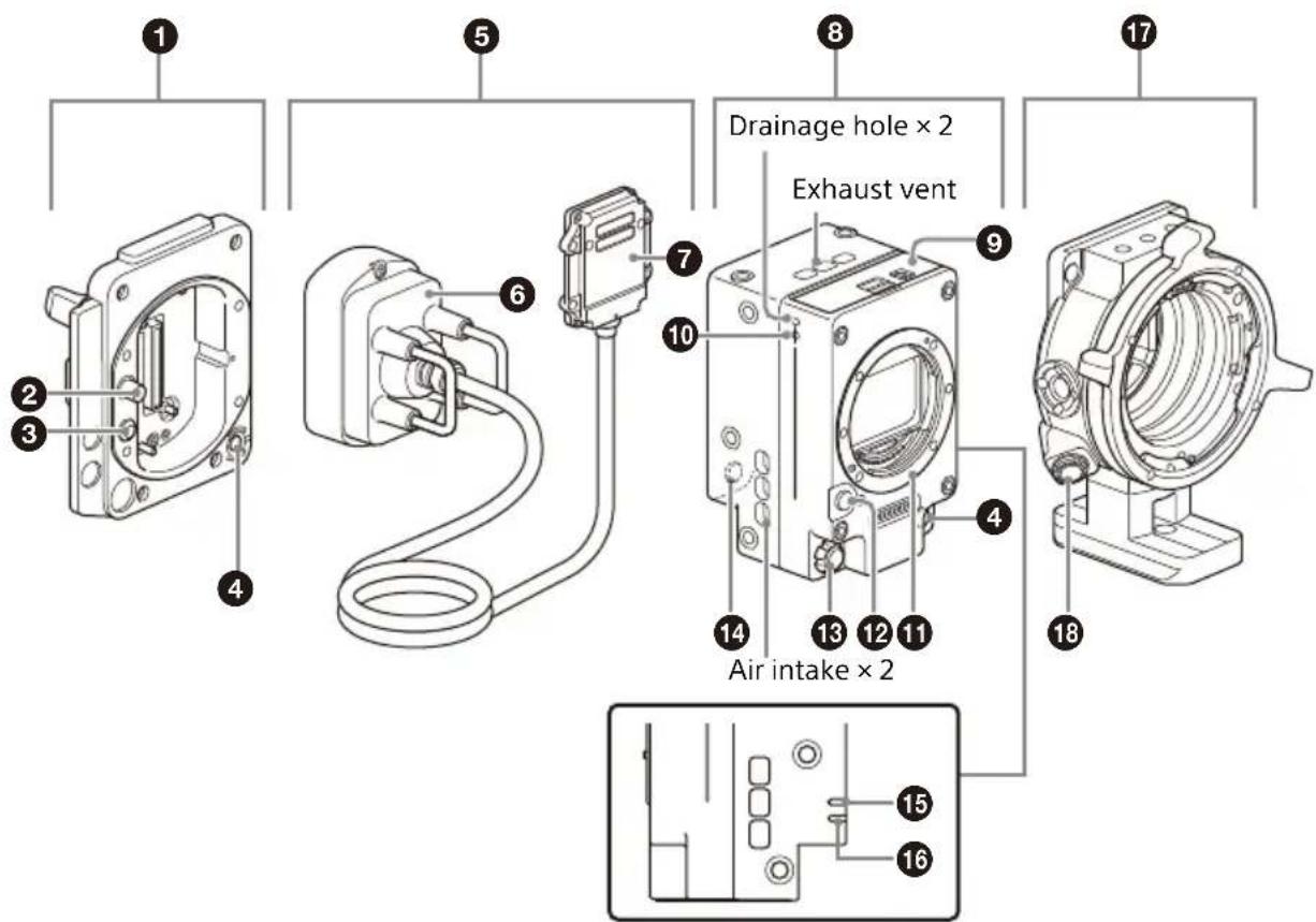
① Camera body adaptor
Adaptor that attaches to the camera body to extend the imager block.
② MONITOR IN connector (BNC type)
Not supported.
③ 24 V IN connector (Fischer 3-pin)
DC power supply input connector that supplies the external power supply to the imager block adaptor.
④ ASSIGN (assignable) button 3
Toggles the assigned function between on/off (enable/disable) or activates the function with each press.
The lamp is lit orange when the assigned function is on (enabled) or activated.
For details about function assignment, refer to the MPC-3628/MPC-3626 Operating Instructions.
⑤ Detachable cable
4.5 m detachable extension cable for connection between the camera body adaptor and camera head.
6 Receiver
Receiver adaptor that connects to the camera body adaptor.
7 Transceiver
Adaptor that connects to the camera head.
⑧ Camera head
Imager block equipped with an 8.6K CMOS image sensor.
9 ND filter slot block
Slot for inserting the supplied ND filters.
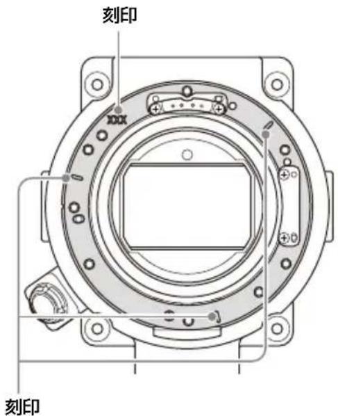
10 (phi) mark
The (phi) mark indicates the position of the image sensor surface.
Use this mark as a reference to accurately measure the distance from the camera to the subject.
11 E-mount block
12 Lens release button
13 24 V OUT connector (Fischer 3-pin)
External power supply output connector. It outputs the power supply connected to the 24 V IN connector of the camera body adaptor.
It can be connected as an external power supply for a lens servo or other device. It can also be used to input a REC Trigger signal.
Notes
- Depending on the output current and the length of the detachable cable, the voltage of the power supply output from this connector may be lower than the voltage of the power supply connected to the 24 V IN connector.
- Detachable cable (4.5 m (14.8 ft)): Approximately 0.50 V drop at 1 A output or 1.00 V drop at 2 A output
- Detachable cable (12 m (39.4 ft)) (option): Approximately 1.40 V drop at 1 A output or 2.80 V drop at 2 A output
- For details about Fischer 3-pin connector specifications, refer to the MPC-3628/MPC-3626 Operating Instructions.
14 ASSIGN (assignable) button 5
Toggles the assigned function between on/off (enable/disable) or activates the function with each press.
The lamp is lit orange when the assigned function is on (enabled) or activated.
For details about function assignment, refer to the MPC-3628/MPC-3626
Operating Instructions.
15 LED(red)
Functions as REC lamp and error/warning indicator.
16 LED (green)
Lit when the power supply is on.
17 PL-mount adaptor
18 LENS META IN connector (LEMO 4-pin)
Lens metadata input connector. Connector used on the unit: LEMO EGG.0B.304.CLL
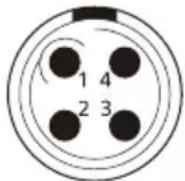
No. Signal
1 Data IN
2 Data OUT
3 GND
4 NC
Communications protocol: Cooke/i
Communications levels: RS-232C
Typical compatible connector (reference only): LEMO FGG.0B.304.CLAD56
Notes
- For details about accessory mounting holes, see the external dimensions drawing at the back of this document.
- Before connecting, turn off both the unit and the device to which you are connecting.
- Be sure to connect an RS-232C compatible lens metadata communications device correctly. Incorrect signal connection may damage the device.
Attaching to the Camera
Notes
- Turn off the camera and wait 30 minutes or longer to allow it to cool sufficiently before attaching/removing the unit.
Perform the operation quickly in a dust-free location to prevent dust and other matter from entering the camera and adaptors.
• Take care not to damage the connectors and parts. - A data transfer error may occur if there is any dust or other matter adhering to the adaptor connectors. If this occurs, clean the connector.
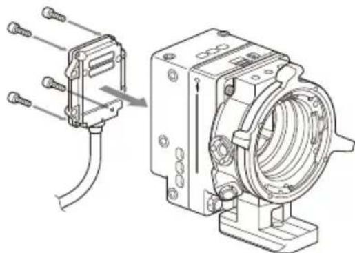
1 Remove the four hex screws on the bottom and remove the bottom plate (①), then remove the four hex screws on the front and remove the imager block from the camera body (②).
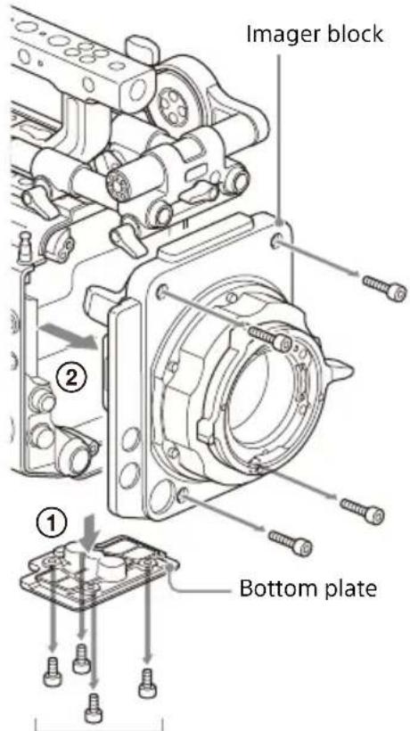
Short screws
Note
Orient the lens side face down when placing the removed imager block on a flat surface. If the heat sink side is placed face down, the flange back distance (flange focal distance) may change.
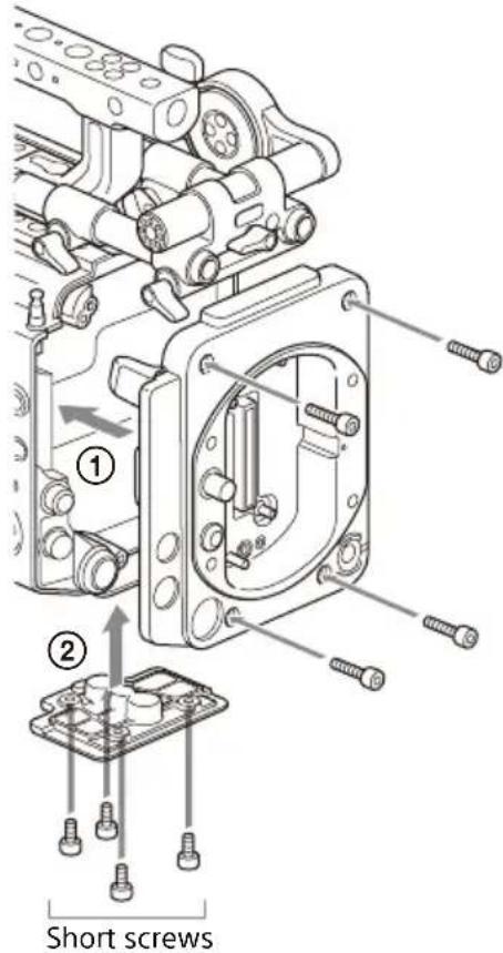
2 Attach the camera body adaptor (①) and then attach the bottom plate (②).
Align and attach using the eight hex screws, removed in step 2, and tighten using a hex wrench (tightening torque of 1.4 N·m).
3 Attach the detachable cable receiver to the camera body adaptor.
Align with the index marks on the sides of the receiver, and attach using the two hex screws, and tighten using a hex wrench (tightening torque of 1.4 N·m).
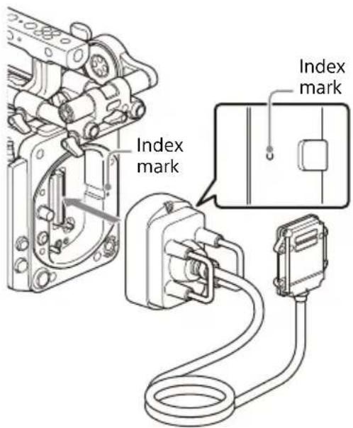
4 Attach the transceiver of the detachable cable to the camera head.
Align and attach using the four supplied hex screws, and tighten using a hex wrench (tightening torque of 1.4 N·m).
natural_image
Technical line drawing of a mechanical component with threaded pins and a separate view showing internal structure (no text or symbols)Note
If the camera body adaptor, detachable cable, and camera head are not securely attached, the MPC-3628/MPC-3626 will not start up. Attach the devices securely.
Removing from camera
1 Remove the transceiver from the camera.
2 Remove the receiver from the camera body adaptor.
3 Remove the camera body adaptor from the camera body.
4 Attach the imager block to the camera body (tightening torque of 1.4 N·m).
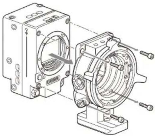
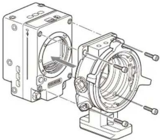
Removing the PL-mount adaptor
Remove the four hex screws using a hex wrench and remove the PL-mount adaptor from the camera head.
natural_image
Technical illustration of a mechanical assembly with housing and mounting components (no text or symbols)To attach the PL-mount adaptor
Align and attach using the four supplied hex screws, and tighten using a hex wrench (tightening torque of 1.4 N·m).
natural_image
Technical line drawing of a mechanical assembly showing two views of a housing with bolts and a central component (no text or symbols present)Attaching a PL-mount lens
1 Remove the mount cover from the lens mount by turning the PL-mount lever counterclockwise.
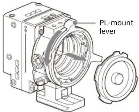
Note
Turn the PL-mount lever counterclockwise to the stopper position.
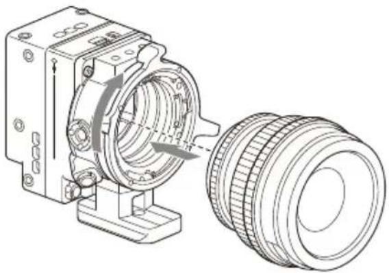
2 Insert the lens into the lens mount by aligning the concave part of the lens with the positioning pin on the upper right of the lens mount.
3 Secure the lens by turning the PL-mount lever clockwise while holding the lens.
natural_image
Technical line drawing of a mechanical assembly with a cylindrical component and a flanged housing (no text or symbols)Note
Do not turn the lens when attaching the PL-mount lens. It may cause damage to the hot shoe pin.
To attach a Cooke /i lens
Align the contacts on the lens with the hot shoe of the unit.
To remove the lens
1 Turn the PL-mount lever counterclockwise while holding the lens from underneath.
2 Pull the lens forward.
Notes
- If another lens will not be attached soon, carefully align the concave part of the mount cover, then secure the mount cover by turning the PL-mount lever clockwise.
- For correct I/F communication with the lens, set the Lens Configuration settings on the MPC-3628/MPC-3626 to match the lens in use. For details about configuration, refer to the MPC-3628/MPC-3626 Operating Instructions.
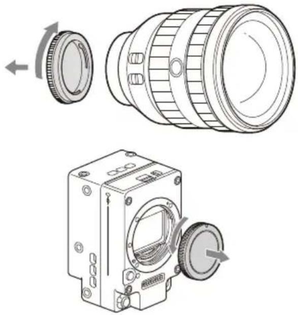
Attaching an E-mount lens
1 Remove the cap and cover from the unit and the lens.
natural_image
Technical line drawing of a camera module with external components and rotation arrows (no text or symbols)2 Align the lens mount mark (white) with the unit, carefully insert the lens, and then turn the lens clockwise.
A click sound can be heard when it locks into position.
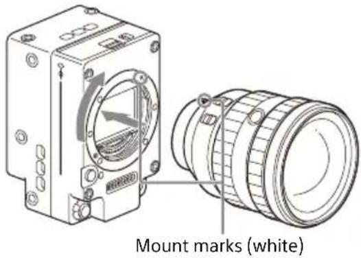
Note
Do not press the lens release button when attaching a lens.
To remove the lens
Remove a lens using the following procedure.
1 Press and hold the lens release button and turn the lens counterclockwise while supporting the lens.
2 Pull the lens forward.
Notes
- When removing a lens, align the mount mark on the lens lock ring with the mount mark on the camcorder.
- Grasp the lens securely in your hand to prevent the lens from falling.
- If another lens will not be attached immediately, always attach the body cap.
Adjusting the flange focal length
The unit is shipped with the flange focal length already adjusted. If you need to adjust the flange focal length, remove the lens mount, and change the shims with those of the appropriate thickness. You can adjust the thickness by ±0.1 mm in 0.01 mm increments.
Shims
The following shims are supplied with the unit.
0.05 mm × 1 (circular)
0.01 mm × 15 (1/3 arc)
1/3 arc shims should always be used as a set of three shims. Insert shims to increase the flange focal length. The unit is shipped with the flange focal length already adjusted using the following three types of shims.
0.10 mm (circular)
0.05 mm (circular)
0.01 mm (1/3 arc)
A seal is attached showing the shim thickness when shipped.
Adjusting the flange focal length
1 Remove the six Torx screws and remove the PL-mount flange.
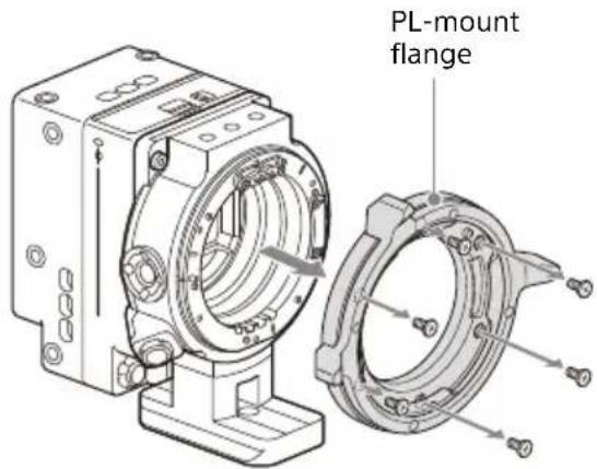
2 Loosen the four Phillips screws securing the PL connectors and plate, and remove the PL connectors, PL connector block, and plate.
3 Attach shims to the PL-mount adaptor (three locations).
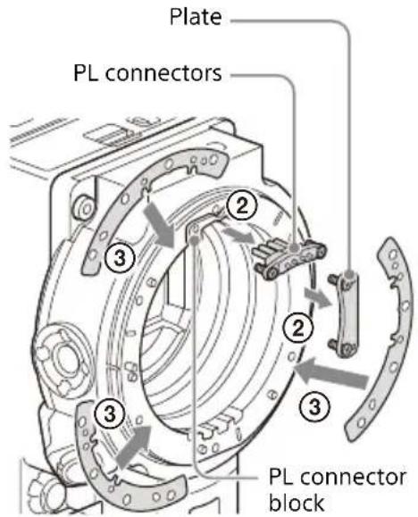
When using 1/3 arc shims
Attach shims so that they have the same thickness in all three locations.
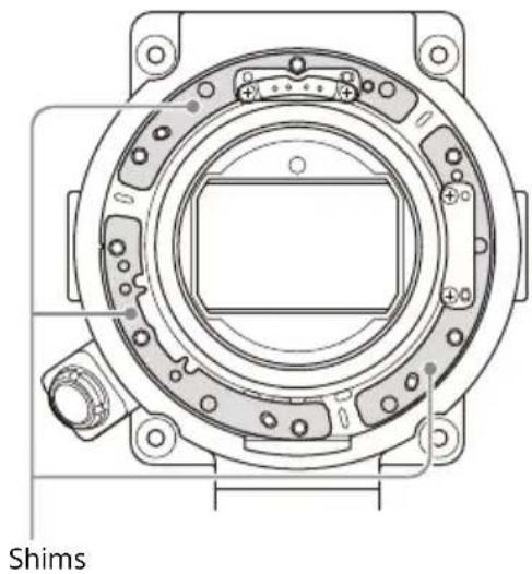
natural_image
Technical line drawing of a mechanical assembly with labeled 'Shims' (no other text or symbols)When using circular shims
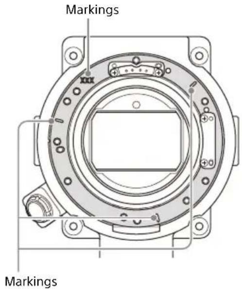
Attach with the surface that has markings on it facing the front.
Removing the ND filter
Note
Avoid touching the surface directly to avoid scratching or leaving fingerprints on the filter. When installing or removing the filter, hold it by the frame.
1 Open the cover of the ND filter slot block.
Push the lock switch to the right to unlock the cover (①) and push the open/close switch to the OPEN position (②).
The ND filter is ejected slightly.

2 Gently press the ND filter (③).
The lock is released and the ND filter is fully ejected.
3 Remove the ND filter (④).
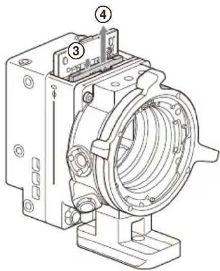
Note
If the ND filter is pushed in, it will be relocked. If locked, close the cover of the ND filter slot block and start again from step 1.
Inserting an ND filter
1 Open the cover of the ND filter slot block.
2 Insert the ND filter with the side with the filter name facing the front into the ND filter slot until it clicks into place.
Insert the ND filter as shown in the following diagram, paying attention to the vertical orientation and front/rear surfaces.
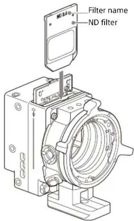
3 Close the cover and push the open/close switch to the CLOSE position.
When closing the cover, the ND filter will be pushed out slightly, but this is not a malfunction.
4 Push the lock switch to the left to lock the cover.
Notes
- The density of the inserted ND filter is displayed on the viewfinder/monitor screen of the camera.
- If an ND filter is not inserted or if the type of ND filter cannot be recognized, a message will be
displayed on the sub-display screen of the camera and the REC lamp will start flashing.
About the startup time
When you connect the MPC-3628/MPC-3626 main unit and the CBK-3621XS for the first time, it may take about 5 minutes for the camera to start up, depending on the project frame rate and imager mode settings.
About APR operation time
After APR (Auto Pixel Restoration) execution finishes, it takes about 120 seconds to save data. Consequently, it will take about 120 seconds for the power to turn off if you turn off the power during this time. Also, if a reboot occurs as a result of changing settings, the reboot operation will be extended by about 120 seconds.
Inspection and Maintenance
Inspection before shooting
Inspect the unit before shooting to make sure that the system is operating normally.
Cleaning
Wipe off dirt on the exterior and any metallic powder created by attachment/removal using a soft, dry cloth. In extreme cases, use a cloth moistened in a little neutral detergent, then wipe dry.
Do not use organic solvents, such as alcohol or thinners, as these may cause discoloration or other damage to the finish of the unit.
Do not clean the unit with an air blower. Dust and other particles suspended in the air may enter the unit and cause a malfunction. Also, refrain from cleaning with high air pressure equipment, such as an air duster, as these may damage optical components.
- Using the unit with dirt or dust adhering to the connector between the camera body and sensor block may cause a failure or malfunction. When storing, be careful not to let dirt accumulate.
- If the contacts of the pogo pin type connectors become dirty, poor connection may cause a malfunction. If an error or other problem occurs, gently wipe off any dirt with a soft cloth or cotton swab.
- The cable may become twisted and tangled if coiled in a single loop. Wind the cable in a figure of eight.
Notes on Device Connections
- A Sony audio wireless receiver cannot be used for connecting the CBK-3621XS.
Notes on Handling Cables
- Do not crush, bend, or damage the cable.
- Be careful when coiling and installing the cable so that the cable is not subject to strong twisting.
- Minimum coil diameter for guaranteed cable operation: 45 mm (1 13/16 inches) or higher
Specifications
General
Power consumption
Approx. 15 W (max) (5.5K 2.39:1120 FPS)
Operating temperature
0 °C to 40 °C (32 °F to 104 °F)
Storage temperature
-20^ to +60^ (-4^ to +140^)
External dimensions
Refer to the back of this document.
Mass
Camera head
Approx. 0.54 kg (1 lb 3.0 oz)
Camera head + PL-mount adaptor
Approx. 1.05 kg (2 lb 5.0 oz)
4.5 m cable
Approx. 0.86 kg (1 lb 14.3 oz)
Camera body adaptor
Approx. 0.36 kg (12.7 oz)
Input/output connectors
24 V IN connector (Fischer 3-pin) (1)
24 V OUT connector (Fischer 3-pin) (1)
LENS META IN connector (LEMO 4-pin)
(1)
Supplied accessories
ND filters (9)
Shim (circular) (1) (4-730-328-11)
Shims (1/3 arc) (15) (4-730-328-21)
E-mount lens cap (1)
PL-mount lens cap (1)
Screws for receiver (2) (5-000-390-02)
Operating Instructions (1)
Warranty (1)
Design and specifications are subject to change without notice.
Notes
- Always verify that the unit is operating properly before use. SONY WILL NOT BE LIABLE FOR DAMAGES OF ANY KIND INCLUDING, BUT NOT LIMITED TO, COMPENSATION OR REIMBURSEMENT ON ACCOUNT OF THE LOSS OF PRESENT OR PROSPECTIVE PROFITS DUE TO FAILURE OF THIS UNIT, EITHER DURING THE WARRANTY PERIOD OR AFTER EXPIRATION OF THE WARRANTY, OR FOR ANY OTHER REASON WHATSOEVER.
- SONY WILL NOT BE LIABLE FOR CLAIMS OF ANY KIND MADE BY USERS OF THIS UNIT OR MADE BY THIRD PARTIES.
- SONY WILL NOT BE LIABLE FOR THE TERMINATION OR DISCONTINUATION OF ANY SERVICES RELATED TO THIS UNIT THAT MAY RESULT DUE TO CIRCUMSTANCES OF ANY KIND.
Français
2235 Sheppard Avenue East, Suite 700, Toronto, Ontario M2J 5B5, Canada
4 Bouton ASSIGN (assignable) 3
14 Bouton ASSIGN (assignable) 5
natural_image
Technical illustration of a mechanical assembly showing a connector with pins and a separate motor housing (no text or symbols present)Remarque
natural_image
Technical line drawing of a mechanical assembly with housing and mounting base (no text or symbols)natural_image
Technical line drawing of a mechanical assembly with two views of a housing (no text or symbols present)natural_image
Technical line drawing of a mechanical assembly with two views: top view showing internal components and side view showing external ring (no text or symbols)Remarque
natural_image
Technical line drawing of a camera module with two views: top shows lens assembly, bottom shows motor housing (no text or symbols)natural_image
Technical line drawing of a mechanical component with concentric rings and mounting holes (no text or symbols)Remarque
natural_image
Technical line drawing of a mechanical assembly with two views: one showing a connector and cable, the other showing a motor or electrical component (no text or symbols present)Hinweis
natural_image
Technical line drawing of a mechanical assembly with two views of a housing (no text or symbols present)natural_image
Technical illustration of a mechanical assembly with two views of a housing and mounting base (no text or symbols)natural_image
Technical line drawing of a mechanical assembly with a cylindrical component and a flanged housing (no text or symbols)Hinweis
natural_image
Technical line drawing of a camera module with rotating components and rotation arrows (no text or symbols)2 Richten Sie die
natural_image
Technical line drawing of a mechanical device with a separate cylindrical component (no text or symbols)Hinweis
natural_image
Technical line drawing of a mechanical assembly with connectors and housing (no text or symbols)Nota
natural_image
Technical line drawing of a mechanical assembly with two views of a housing (no text or symbols present)natural_image
Technical illustration of a mechanical assembly showing two views of a housing with bolts and a central component (no text or symbols present)Nota
natural_image
Technical line drawing of a mechanical assembly with a cylindrical component and a flanged cylindrical component (no text or symbols)Nota
natural_image
Technical line drawing of a camera module with external components and rotation arrows (no text or symbols)natural_image
Technical line drawing of a mechanical component with no visible text or symbolsNota
natural_image
Technical line drawing of a mechanical component with threaded pins and a separate view showing internal structure (no text or symbols)Nota
natural_image
Technical line drawing of a mechanical assembly with two views of a housing (no text or symbols present)natural_image
Technical line drawing of a mechanical assembly with housing and mounting base (no text or symbols)natural_image
Technical line drawing of a mechanical assembly with two views: one showing internal components and the other showing a cylindrical component (no text or symbols present)Nota
natural_image
Technical line drawing of a camera lens with an arrow indicating rotation (no text or symbols)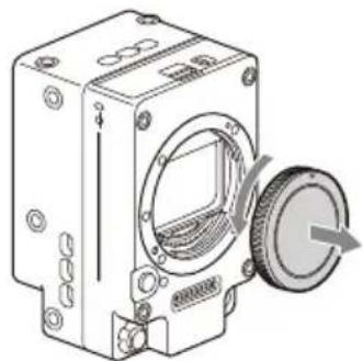
natural_image
Technical line drawing of a mechanical device with a circular component and a rotating knob (no text or symbols)natural_image
Technical line drawing of a mechanical device with a close-up view of its cylindrical component (no text or symbols present)natural_image
Technical line drawing of a circular mechanical component with mounting holes and a central square aperture (no text or symbols)Al usar arandelas circulares
Nota
短螺钉
natural_image
Technical illustration of a mechanical assembly showing a connector with pins and a separate housing (no text or symbols present)注意
natural_image
Technical illustration of a mechanical assembly with two views of a bearing housing (no text or symbols present)安装PL卡口适配器
natural_image
Technical illustration of a mechanical assembly with two views of a bearing housing (no text or symbols present)安装PL卡口镜头
natural_image
Technical line drawing of a mechanical assembly with a cylindrical component and a flanged housing (no text or symbols)注意
natural_image
Technical line drawing of a camera module with two views: top shows lens assembly, bottom shows motor housing (no text or symbols)natural_image
Technical line drawing of a mechanical device with a side view showing internal components and a close-up of its cylindrical component (no text or symbols present)安装标记(白色)
注意
安装镜头时,请勿按下镜头释放按钮。
取下镜头
按照下列步骤取下镜头。
注意
natural_image
Technical illustration of a mechanical assembly with two views: one showing a connector and cable, the other showing a cylindrical component (no text or symbols present)Примечание
natural_image
Technical line drawing of a mechanical assembly with two views of a housing (no text or symbols present)natural_image
Technical line drawing of a mechanical assembly with two views of a bearing housing (no text or symbols present)natural_image
Technical line drawing of a mechanical assembly with two views: one showing a cylindrical component and the other showing a flanged cylindrical component (no text or symbols present)Примечание
natural_image
Technical line drawing of a camera module with two views: top shows lens assembly, bottom shows motor housing (no text or symbols)natural_image
Technical line drawing of a mechanical component with concentric rings and mounting holes (no text or symbols)Примечание
natural_image
Technical illustration of a mechanical component with threaded pins and a separate view showing internal structure (no text or symbols)Luyý
natural_image
Technical illustration of a mechanical assembly with housing and mounting components (no text or symbols)natural_image
Technical illustration of a mechanical assembly showing two views of a housing with bolts and a central component (no text or symbols present)natural_image
Technical line drawing of a mechanical assembly with a cylindrical component and a flanged housing (no text or symbols)Lưu ý
natural_image
Technical line drawing of a camera module with external components and rotation arrows (no text or symbols)Lưu ý
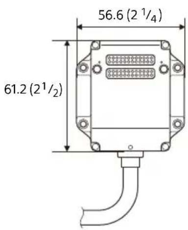
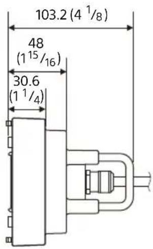
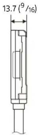
Unit: mm (inches)
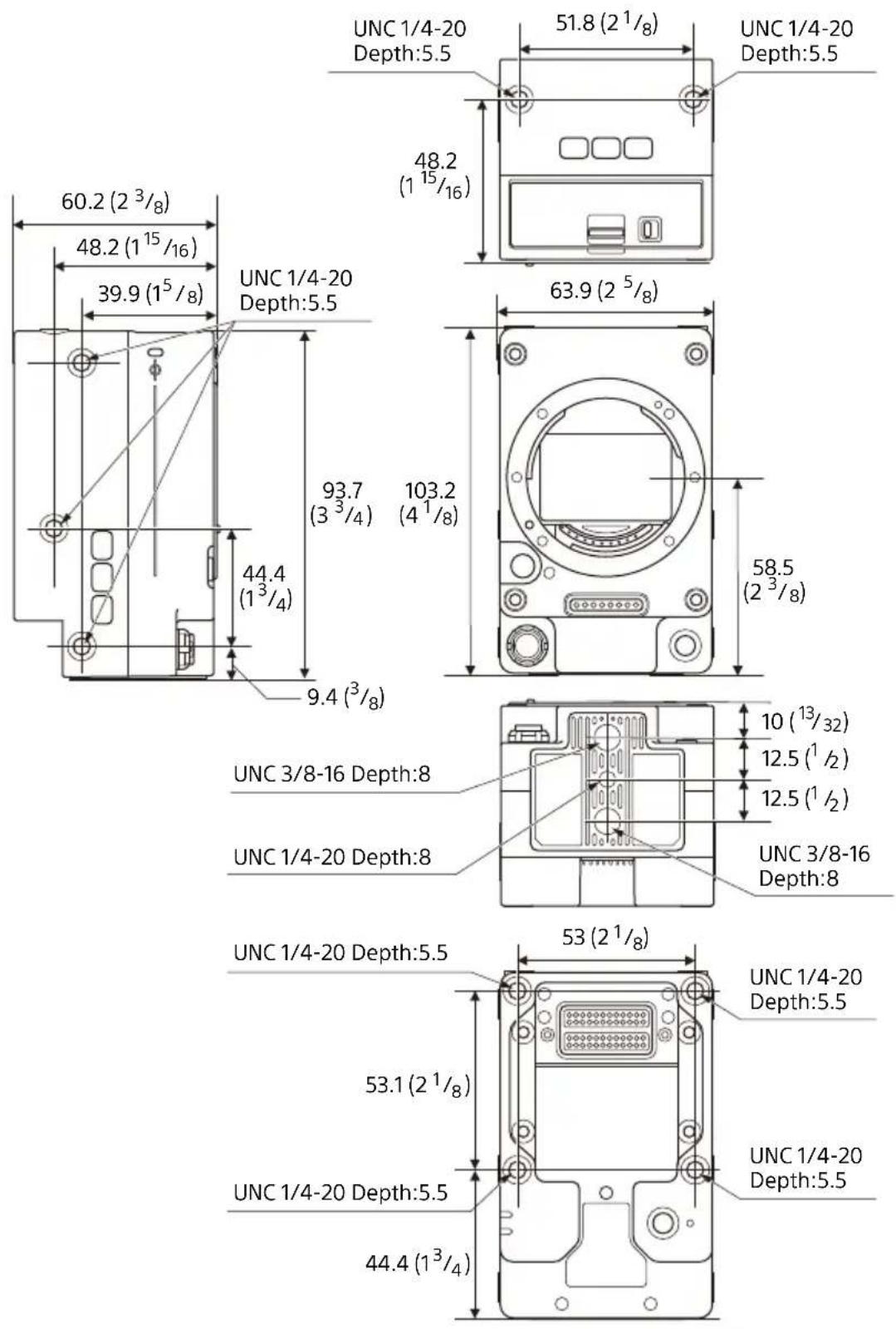
Unit: mm (inches)
ملاحظات
ملاحظة
natural_image
Technical line drawing of a camera module with a close-up view of its lens (no text or symbols present)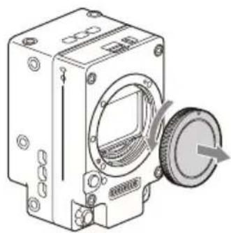
natural_image
Technical line drawing of a mechanical device with a circular component and a rotating knob (no text or symbols)natural_image
Technical line drawing of a mechanical assembly with a cylindrical component and a flanged housing (no text or symbols)ملاحظة
natural_image
Technical line drawing of a mechanical assembly with housing and mounting base (no text or symbols)natural_image
Technical line drawing of a mechanical assembly with housing and mounting base (no text or symbols)قم إزالة المُم
natural_image
Technical line drawing of a mechanical assembly with connectors and housing (no text or symbols)ملاحظة
براغي قصيرة
التوصيل بالكاميرا
ملاحظات

- 安全のために
- ご注意
- PLマウントアダプターを取り付けるには
- PLマウントレンズを取り付ける
- 円弧型のシムを使用する場合
- NDフィルターを取り出す
- Caution
- For the customers in the U.S.A.
- Supplier's Declaration of Conformity
- For the customers in Canada
- WARNING
- ATTENTION
- For the customers in Europe
- For the customers in Korea
- WARNING CAUTION
- Usage Precautions
- To prevent electromagnetic interference from portable communications devices
- Camera CMOS image sensor phenomena
- Note
- White flecks
- Flicker
- Precautions relating to the ND filters
- Features
- Location and Function of Parts
- ① Camera body adaptor
- ② MONITOR IN connector (BNC type)
- ③ 24 V IN connector (Fischer 3-pin)
- ④ ASSIGN (assignable) button 3
- ⑤ Detachable cable
- Receiver
- Transceiver
- ⑧ Camera head
- ND filter slot block
- (phi) mark
- E-mount block
- Lens release button
- 24 V OUT connector (Fischer 3-pin)
- Notes
- ASSIGN (assignable) button 5
- LED(red)
- LED (green)
- PL-mount adaptor
- LENS META IN connector (LEMO 4-pin)
- No. Signal
- Attaching to the Camera
- Attach the detachable cable receiver to the camera body adaptor.
- Attach the transceiver of the detachable cable to the camera head.
- Removing from camera
- Removing the PL-mount adaptor
- To attach the PL-mount adaptor
- Attaching a PL-mount lens
- To attach a Cooke /i lens
- To remove the lens
- Attaching an E-mount lens
- Adjusting the flange focal length
- Shims
- Remove the six Torx screws and remove the PL-mount flange.
- When using 1/3 arc shims
- When using circular shims
- Removing the ND filter
- Open the cover of the ND filter slot block.
- Gently press the ND filter (③).
- Remove the ND filter (④).
- Inserting an ND filter
- About the startup time
- About APR operation time
- Inspection and Maintenance
- Inspection before shooting
- Cleaning
- Notes on Device Connections
- Notes on Handling Cables
- Specifications
- General
- Input/output connectors
- Supplied accessories
- Français
- Bouton ASSIGN (assignable) 5
- Remarque
- Hinweis
- Nota
- Al usar arandelas circulares
- 注意
- 安装PL卡口适配器
- 安装PL卡口镜头
- 取下镜头
- Примечание
- Luyý
- Lưu ý
- التوصيل بالكاميرا
- ملاحظات
Brand : SONY
Model : CBK-3621XS
Category : Camera