
PSS-650 - Projector Accessory SONY - Free user manual and instructions
Find the device manual for free PSS-650 SONY in PDF.

| Product type | Projector suspension mount |
| Brand | Sony |
| Model | PSS-650 |
| Dimensions (W × H × D) | Approx. 299 mm × 300 mm × 453.5 mm (11 25/32 × 11 13/16 × 17 27/32 in) |
| Weight | Approx. 8.6 kg (19 lb) |
| Maximum load | 30 kg (66 lb 2 oz) |
| Height adjustment range (without extension tube) | 300 mm to 375 mm (11 13/16 to 14 3/4 in) |
| Height adjustment range (with extension tube) | 475 mm to 625 mm (18 11/16 to 24 19/32 in) |
| Horizontal rotation angle | ±10° |
| Left/right tilt angle | ±5° |
| Up/down tilt angle | ±5° |
| Front/rear position adjustment | ±50 mm (1 31/32 in) |
| Left/right position adjustment | ±25 mm (31/32 in) |
| Main materials | Steel (estimated) |
| Included accessories | Brackets, anti-fall cable, covers, screws, manual |
| Safety | Metal anti-fall cable, minimum ceiling load 200 kg |
| Maintenance | Clean with a soft, dry cloth. Do not use solvents. |
| Warranty | Sony limited warranty (see manual for details) |
Frequently Asked Questions - PSS-650 SONY
User questions about PSS-650 SONY
0 question about this device. Answer the ones you know or ask your own.
Ask a new question about this device
Download the instructions for your Projector Accessory in PDF format for free! Find your manual PSS-650 - SONY and take your electronic device back in hand. On this page are published all the documents necessary for the use of your device. PSS-650 by SONY.
USER MANUAL PSS-650 SONY
Projector Suspension Support
特約店様用取付説明書 JP
Installation Manual for Dealers ____ GB
© 2015 Sony Corporation

4381862020
日本語
ご注意
natural_image
Technical line drawing of a mechanical assembly with mounting flanges and a central component (no text or symbols)調整ブラケット (1)
natural_image
Technical line drawing of a mechanical assembly with mounting flanges and a central cylindrical component (no text or symbols)natural_image
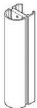
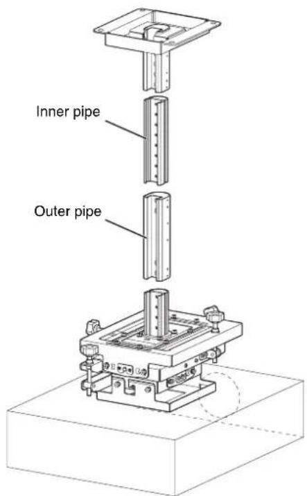
Isometric line drawing of a square mechanical housing with mounting brackets (no text or symbols)延長パイプ(アウターパイプ)(1)
延長パイプ(インナーパイプ)(1)

配線カバー(インナーパイプ用)(4)
配線カバー(アウターパイブ用)(4)

振れ防止ワイヤー用ブラケット(2)

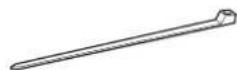
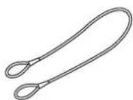
落下防止ワイヤー(1)
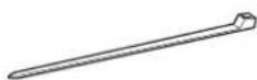
ケーブルクランプ (2)
ネジ BSW 5 × 12 (3)

ネジ K6 × 12 (6)

ボルト M6 × 16 (4)

ネジ P4 × 6 (6)

ネジ P5 × 12 (6)

ネジ PSW 4 × 10 (4)

取付説明書(本書)(1)
ご注意
natural_image
Technical line drawing of a mechanical assembly with mounting holes and a central cylindrical component (no text or symbols)flowchart
graph TD
    A["Step A: Solid rectangle with upward arrow"] --> B["Step B: Rectangular prism with dashed outline"]
    B --> C["Step C: Inverted rectangle with double-headed arrows"]
    D["Step D: Solid rectangle with left-pointing arrow"] --> E["Step E: Inverted rectangle with double-headed arrow"]
参考
This installation manual is for Sony dealers.
This manual shows the correct handling of the projector ceiling mount and important precautions necessary to prevent accidents. Be sure to read this manual thoroughly and to do the installation work safely. Keep this manual available for future reference.
For customers
Sufficient expertise is required for installing this projector ceiling mount. Be sure to subcontract the installation to Sony dealers or licensed contractors and pay special attention to safety during the installation.
For dealers
Sufficient expertise is required for installing this projector ceiling mount. Be sure to read this manual thoroughly to do the installation work. Sony is not liable for any damage or accident, such as falling, etc., caused by mishandling or improper installation. Please give this manual to the customer after installation.
The PSS-650 Projector Suspension Support is for hanging Sony projectors from a ceiling.
This manual describes the installation for a Sony VPL-FHZ65 projector.
Maximum load: 30 kg (66 lb 2 oz)
For the customers in the U.S.A.
SONY LIMITED WARRANTY - Please visit http://www.sony.com/psa/warrantyfor important information and complete terms and conditions of Sony's limited warranty applicable to this product.
For the customers in Canada
SONY LIMITED WARRANTY - Please visit http://www.sonybiz.ca/pro/lang/en/ca/article/resources-warranty for important information and complete terms and conditions of Sony's limited warranty applicable to this product.
For the customers in Europe
Sony Professional Solutions Europe - Standard Warranty and Exceptions on Standard Warranty. Please visit http://www.pro.sony.eu/warrantyfor important information and complete terms and conditions.
For the customers in Korea
SONY LIMITED WARRANTY - Please visit http://bpeng.sony.co.kr/handler/BPAS-Startfor important information and complete terms and conditions of Sony's limited warranty applicable to this product.
Table of Contents
Supplied Parts 18
Mounting Configuration 19
Top View 19
Front View 19
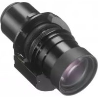
Configuration when using VPLL-3003 Projection Lens 20
Before Attaching 21
Attaching to the Ceiling 22
Assembling the Ceiling Mounting Bracket ..... 22
Attaching the Ceiling Mounting Bracket to the Ceiling 23
Attaching the Projector Mounting Bracket ..... 23
Attaching the Projector to the Adjustment Bracket 24
Attaching the Fall Prevention Wire 25
Attaching the Wiring Covers 25
Adjusting the Angle and Position 26
Adjustment procedure 26
Attaching the Brackets for Tension Wires ..... 28
Typical Ceiling Attachment 28
Specifications 29
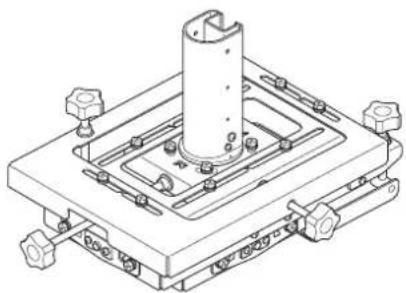
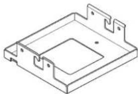
Supplied Parts
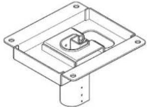
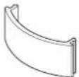
Ceiling mounting bracket (1)
natural_image
Technical line drawing of a mechanical mounting bracket with mounting holes and internal cavity (no text or symbols)Adjustment bracket (1)
natural_image
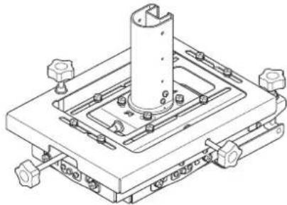
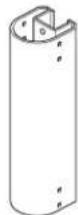
Technical line drawing of a mechanical assembly with mounting flanges and a central cylindrical component (no text or symbols)Projector mounting bracket (1)
natural_image
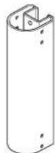
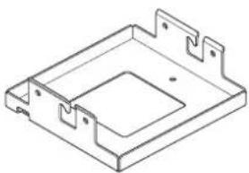
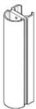
Isometric line drawing of a mechanical housing or bracket with mounting flanges (no text or symbols)Extension pipe (outer pipe) (1)

Extension pipe (inner pipe) (1)
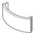
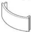
Wiring cover (for inner pipe) (4)
Wiring cover (for outer pipe) (4)

Bracket for tension wires (2)

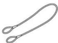
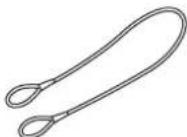
Fall prevention wire (1)
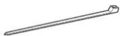
Cable clamp (2)
BSW 5×12 screws (3)

K6×12 screws (6)

M6×16 bolts (4)

P4×6 screws (6)

P5×12 screws (6)

PSW 4×10 screws (4)

Installation Manual (this document) (1)
Note
Use only the supplied parts to attach a projector to the PSS-650 Projector Suspension Support. Do not use other screws, bolts, or wires. Overtightening the screws may damage the projector attachment points.
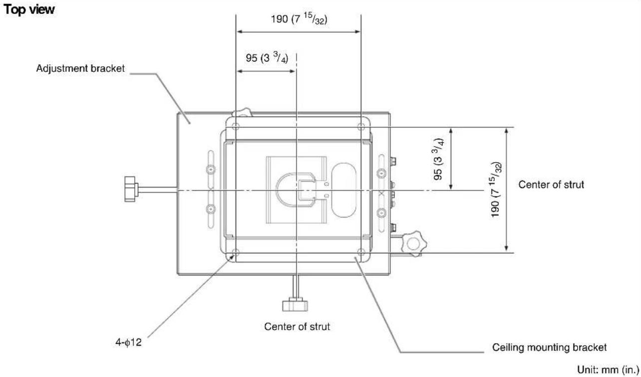
Mounting Configuration
Align the center of the projector lens with the center of the screen.
Top View

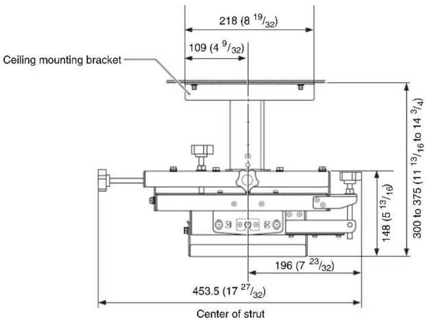
Front View
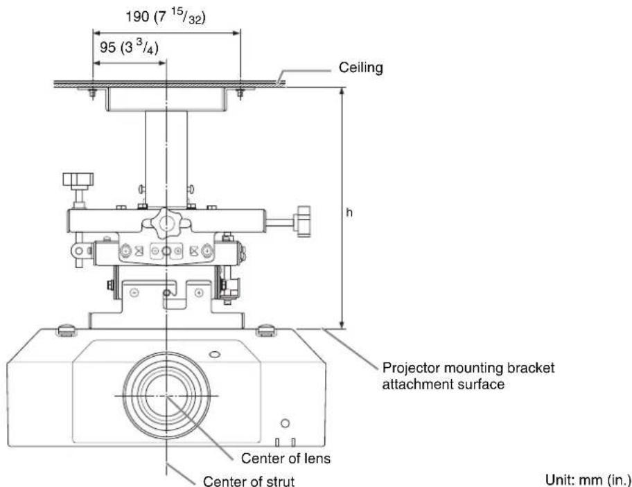
h = Distance from ceiling to projector mounting bracket attachment surface.
When the supplied extension pipe is not used: 300/325/350/375 mm (11 ^13 /16/12 ^25 /32/13 ^25 /32/14 ^3 /4 in.)
When the supplied extension pipe is used: 475 mm to 625 mm ( 18^11/16 in. to 24^19/32 in.) (25 mm ( ^31/_32 in.) adjustment pitch)
When using the optional PSS-650P Projector Suspension Support Joint Pole: 650 mm to 2,975 mm ( 25^19/32 in. to 117^1/8 in.) (25 mm ( ^31/_32 in.) adjustment pitch)
Configuration when using VPLL-3003 Projection Lens
Adjust the mounting position based on the projection distance table.
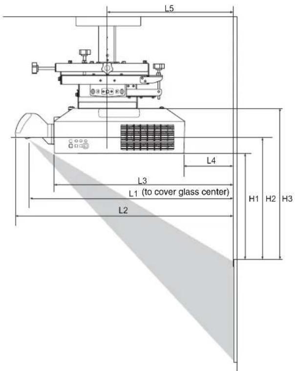
Projection distance table
| Screen size | L1 L2 L3 L4 L5 H1 H2 H3 | ||||||||
| Diagonal D | Horizontal × vertical | ||||||||
| 80 in. (2.03 m) | 1.72 × 1.08 (67^7/_8 × 42^3/_8) | 0.55 (21^1/_2) | 0.66 (26^1/_8) | 0.41 (16^1/_8) | -0.11 (-4^1/_8) | 0.20 (7^7/_8) | 0.30(12) | 0.36(14) | 0.48 (18^3/_4) |
| 100 in. (2.54 m) | 2.15 × 1.35 (84^3/_4 × 53) | 0.69 (27^1/_8) | 0.81 (31^3/_4) | 0.55 (21^5/_8) | 0.03 (1^3/_8) | 0.34 (13^1/_2) | 0.40 (15^3/_4) | 0.45 (17^3/_4) | 0.57 (22^1/_2) |
| 120 in. (3.05 m) | 2.58 × 1.62 (101^3/_4 × 63^5/_8) | 0.83 (32^5/_8) | 0.95 (37^1/_4) | 0.69 (27^1/_4) | 0.18 (6^7/_8) | 0.48(19) | 0.49 (19^3/_8) | 0.54 (21^3/_8) | 0.66 (26^1/_8) |
| 150 in. (3.81 m) | 3.23 × 2.02 (127^1/_4 × 79^1/_2) | 1.04(41) | 1.16 (45^5/_8) | 0.90 (35^1/_2) | 0.39 (15^1/_4) | 0.69 (27^3/_8) | 0.63(25) | 0.69(27) | 0.81 (31^3/_4) |
| 200 in. (5.08 m) | 4.31 × 2.69 (169^5/_8 × 106) | 1.39 (54^7/_8) | 1.51 (59^1/_2) | 1.25 (49^3/_8) | 0.74 (29^1/_8) | 1.05 (41^1/_4) | 0.87 (34^1/_4) | 0.92 (36^1/_4) | 1.04(41) |
| 300 in. (7.62 m) | 6.46 × 4.04 (254^3/_8 × 159) | 2.10 (825/8) | 2.22 (87^1/_4) | 1.96 (77^1/_8) | 1.44 (56^7/_8) | 1.75(69) | 1.34 (52^7/_8) | 1.39 (54^3/_4) | 1.51 (59^1/_2) |
Unit: m (in.)
Projection distance calculation formulas
D: Projection screen size (diagonal in inches)
| L1 L1 = 0.007053 × D - 0.016810(L1 = 0.277674 × D - 0.661950) |
| L2 L2 = 0.007048 × D + 0.101010(L2 = 0.277471 × D + 3.976810) |
| L3 L3 = 0.007048 × D - 0.154990(L3 = 0.277471 × D - 6.101930) |
| L4 L4 = 0.007048 × D - 0.669990(L4 = 0.277471 × D - 26.377520) |
| L5 L5 = 0.007048 × D - 0.363290(L5 = 0.277471 × D - 14.302710) |
| H1 H1 = 0.004712 × D - 0.072000(H1 = 0.185500 × D - 2.834650) |
| H2 H2 = 0.004712 × D - 0.021670(H2 = 0.185500 × D - 0.853150) |
| H3 H2 = 0.004712 × D + 0.099000(H3 = 0.185500 × D + 3.897640) |
Unit: m (in.)
Lens shift
Projection screen Center of lens

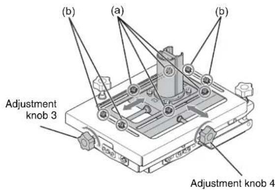
Before Attaching
When shipped, the attachment bracket sliding portion is not positioned in the center.
Use the following procedure to move the sliding portion to the center position to ensure equal front/back and left/right position adjustment range for subsequent adjustment using procedures D) and E) in “Adjusting the Angle and Position” (page 26).
1 Loosen the four M6 bolts (a) securing the front/back position of the slider, and the four M6 bolts (b) securing the left/right position of the slider.
2 Turn adjustment knob 3 counterclockwise to move the slider to the center position.
3 Turn adjustment knob 4 counterclockwise to move the slider to the center position.
Adjust the front/back and left/right position of the slider until the marks are aligned as shown in the following diagram.
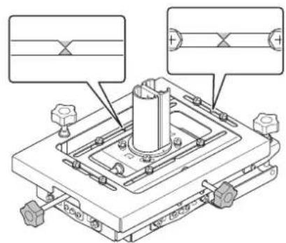
natural_image
Technical diagram of a mechanical assembly with mounting holes and a central cylindrical component (no text or symbols)4 Tighten the four M6 bolts (a) securing the front/back position of the slider, and the four M6 bolts (b) securing the left/right position of the slider.
Attaching to the Ceiling
When tightening screws and bolts, tighten within the rated torque specifications using a torque screwdriver or torque wrench. The tightening torque values for screws and bolts are given below.
M4 screws: 1.4 ± 0.5 N·m
M5 screws: 1.4 ± 0.5 N·m
M6 screws
M6×16: 5 ± 0.5 N·m
K6×12: 2.5 ± 0.5 N·m
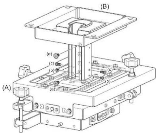
Assembling the Ceiling Mounting Bracket
1 Attach the ceiling mounting bracket (B) to the adjustment bracket (A), and adjust the height (see page 22).
2 Connect the ceiling mounting bracket (B) and adjustment bracket (A) using the two K6×12 screws (a) used to secure the position of the slider.
Note
To securely connect the brackets, place fastening screws at both ends of the adjustment bracket (A) and ceiling mounting bracket (B).
3 Attach the two P4×6 pipe retaining screws (b) and the two P5×12 rattle prevention screws (c).
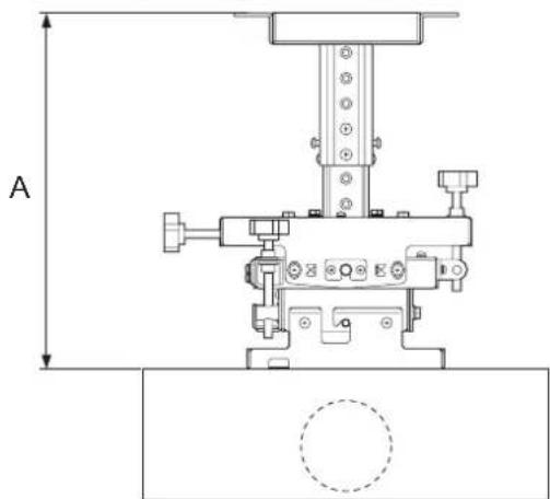
To adjust the height
If not using an extension pipe
Adjustment range: A = 300 mm to 375 mm (11 ^13 / 16 in. to 14 ^3 / 4 in.) (25 mm ( ^31 / _32 in.) adjustment pitch)
* When using a bracket for tension wires: 350 mm to 375 mm (13 ^25 / 32 in. to 14 ^3 / 4 in.)
natural_image
Technical line drawing of a mechanical assembly with no visible text or symbolsIf using an extension pipe
The height adjustment range can be increased using the supplied extension pipe.
Adjustment range: B = 475 mm to 625 mm (18 ^11 /16 in. to 24 ^19 /32 in.) (25 mm ( ^31 /32 in.) adjustment pitch)
* When using a bracket for tension wires: 525 mm to 625 mm ( 20^21/32 in. to 24^19/32 in.)
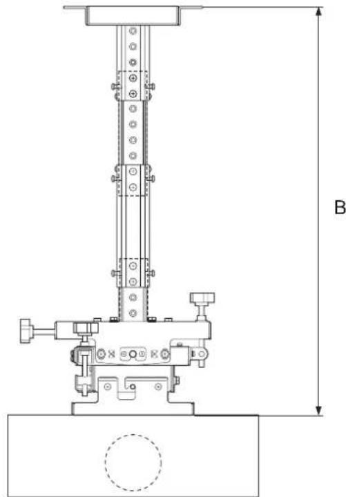
Tip
The height adjustment range can be increased even further by using the PSS-650P Projector Suspension Support Joint Pole (sold separately).
Adjustment range: 650 mm to 2,975 mm (25 ^19/32 in. to 117 ^1/8 in.) (25 mm ( ^31/_32 in.) adjustment pitch)
Attaching the Ceiling Mounting Bracket to the Ceiling
4 Attach the ceiling mounting bracket to the ceiling.
Use commercially available M10 anchor bolts, washers, and nuts (4 locations). These parts are to be supplied by the customer.
The anchor bolts should protrude through the attachment surface of the ceiling mounting bracket by 34 mm to 36 mm ( 1^11/32 in. to 1^13/32 in.).
For details, see "Typical Ceiling Attachment" (page 28).
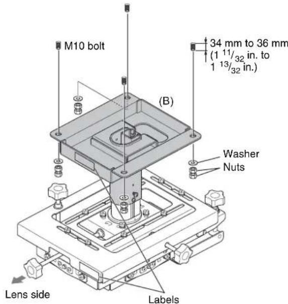
Note
Attach the ceiling mounting bracket and adjustment bracket so that the attached "LENS SIDE" labels are facing the lens side.
Attaching the Projector Mounting Bracket
5 Turn the projector upside down, and attach the projector mounting bracket (C).
Tighten the three BSW 5×12 screws (d), in the order 1 to 3.
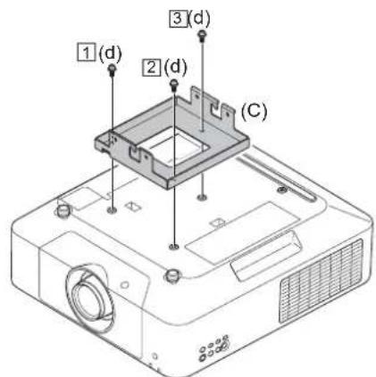
- Place the projector on a cloth or other material to prevent scratching the projector or the table surface.
- The BSW 5×12 screws (d) support the projector from falling. Always attach securely.
Attaching the Projector to the Adjustment Bracket
6
Insert the projector mounting bracket (C), with the projector attached, into the hooks of the adjustment bracket assembled in steps 1 to 4.
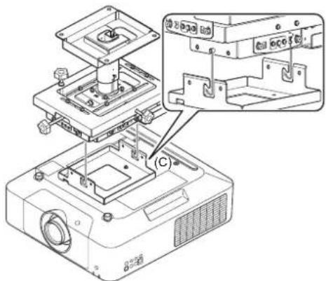
natural_image
Technical line drawing of an electronic device with internal components and a close-up inset showing internal structure (no text or symbols)7
Attach the projector mounting bracket to the adjustment bracket at the four locations on the left and right.
Tighten the four M6×16 bolts (e), in the order 1 to 3.
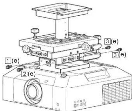
Note
If projector height adjustment is required, disassemble using steps 1 to 7 in the reverse order, and then reassemble from the beginning.
Attaching the Fall Prevention Wire
Install an anchor point and attach the supplied fall prevention wire to make sure the projector cannot fall. Use commercially available M10 anchor bolt, washer, and nuts. These parts are to be supplied by the customer. Use a washer with an outer diameter of 40 mm ( 1^9/_16 in.) or larger.
Note
About projector fall prevention
• Always provide fall prevention measures as described in this manual.
- The length of the supplied fall prevention wire supports the maximum height when using the extension pipe. After adjusting the height, adjust the length of the wire to suit the adjusted height.
- If the supplied wire is insufficient, use a wire made of rust-proof material (for example, stainless steel).
- Use a gage of wire that has sufficient tensile strength to support the weight of the projector and brackets.
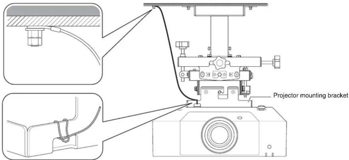
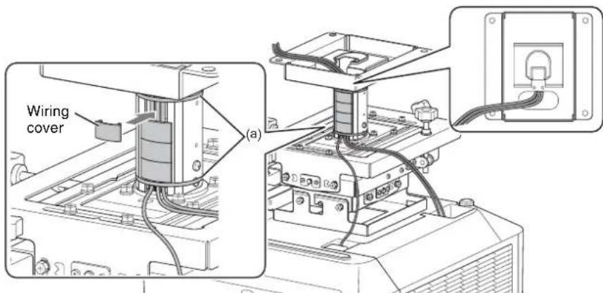
Attaching the Wiring Covers
1 After connecting the wiring and passing cables through the pipe, secure the cables in the pipe using cable clamps (a) to the two locations (top and bottom).
2 When finished, insert the wiring covers into the outer pipe/inner pipe.
Adjusting the Angle and Position
You can adjust the angle of rotation of the projector in the horizontal plane, the up/down/left/right tilt of the projector, and the front/back/left/right position of the projector (see page 22 for details about height adjustment).
- Adjust the projector, without keystone correction on the projector, so that the projected image and the edges of the screen are parallel. Keystone distortion occurs if the screen and the projector are not directly facing each other. Adjust the angle while monitoring the image on the screen until the screen and projector are directly facing each other.
- While referring to the operating guide for the projector, first perform an initial adjustment of the size and focus of the projected image from the projector, adjust the lens shift, and then adjust the angle and position of the projector.
Adjustment procedure
1 If the angle and position do not match the screen, readjust the projector using procedures A) to E).
It is recommended that procedures A) to C) be performed first to reduce image distortion, and then perform adjustment using procedures D) and E).
A)
B
)
D)E)
Tip
If keystone distortion occurs after adjusting the angle of the projector, without keystone correction on the projector, the positions of the screen and projector may be off center. Check the screen and projector are directly facing each other. You can also perform keystone correction on the projector.
2 After all adjustments are completed, tighten all adjustment retaining bolts.
When loosening bolts, take care not to loosen them too much such that they fall out. You can make adjustments by loosening the bolts by one half turn to one full turn.
A) Adjusting the horizontal rotation
Perform this adjustment if the top and bottom edges of the projected image are not parallel.
1 Loosen the four M6 bolts (a) securing the horizontal angle of rotation of the adjustment bracket, and move the projector left/right to adjust the projected image until the top and bottom edges are parallel.
2 When the top and bottom edges are parallel, tighten the four M6 bolts (a).
(a)
Adjustment range
C ±10° adjustment range
B) Adjusting the left/right tilt
Perform this adjustment if the projected image is tilted to the left or right.
1 Loosen the four M6 bolts (a) (2 at front, 2 at rear) securing the left/right tilt of the adjustment bracket.
2 Turn adjustment knob 1 to adjust the projector so that the top and bottom edges of the projected image are parallel with the edges of the screen.
3 When adjustment is completed, securely tighten the M6 bolts (a) (2 at front, 2 at rear).
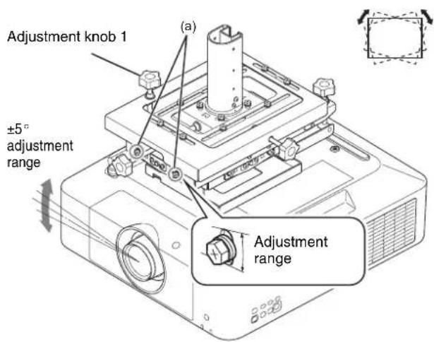
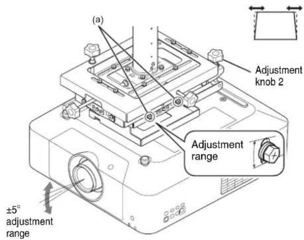
C) Adjusting the up/down tilt
Perform this adjustment if the left and right edges of the projected image are not parallel.
1 Loosen the four M6 bolts (a) (2 on left, 2 on right) securing the up/down tilt of the adjustment bracket.
2 Turn adjustment knob 2 to adjust the projector so that the left and right edges of the projected image are parallel with the edges of the screen.
3 When adjustment is completed, securely tighten the four M6 bolts (a) (2 on left, 2 on right).
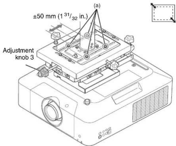
D) Adjusting the front/back position
Perform this adjustment to increase or decrease the size of the projected image.
1 Loosen the four M6 bolts (a) securing the front/back position of the adjustment bracket.
2 Turn adjustment knob 3 to adjust the size of the projected image.
3 When adjustment is completed, securely tighten the four M6 bolts (a).
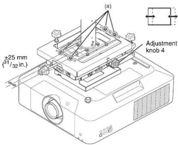
E) Adjusting the left/right position
Perform this adjustment if the projected image is offset to the left or right of the center of the screen.
1 Loosen the four M6 bolts (a) securing the left/right position of the adjustment bracket.
2 Turn adjustment knob 4 to adjust the position of the projected image.
3 When adjustment is completed, securely tighten the four M6 bolts (a).
Attaching the Brackets for Tension Wires
If using wires to prevent shaking, attach the brackets for the swing-prevention tension wires using the four PSW 4×10 screws.
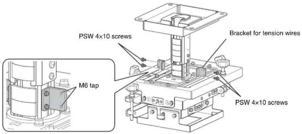
Notes
- When tightening screws and bolts, tighten to 1.4 ± 0.5 ~N · m torque using a torque screwdriver.
- If a bracket for tension wires is attached, the bracket attaches to the bottom end of the pipe and hence reducing the height adjustment range by 50mm (1^31 / _32 in.) (see page 22).
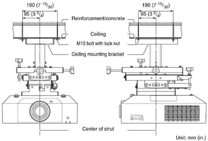
Typical Ceiling Attachment
Caution
Before installing, make sure that the maximum bearing load of the ceiling is 200 kg (441 lb.) or higher.
Specifications
External dimensions
The following dimensions drawings show the adjustment bracket slider in the center position of the adjustment range.
Side view
For details about height adjustment, see "Mounting Configuration" (page 19).
Front view
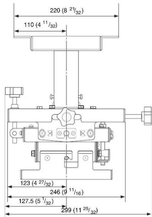
Center of strut
Unit: mm (in.)
Item Description
| Mass Approx. 8.6 kg (19 lb.) | |
| Dimensions (width / height / depth) | Approx. 299 mm × 300 mm × 453.5 mm (11^25/_32 in. × 11^13/_16 in. × 17^27/_32 in.) * When adjustment position is set to minimum height. All other values indicate maximum dimensions in the center position. |
| Adjustment range | |
| Horizontal angle of rotation | ± 10^ |
| Left/right tilt angle | ± 5^ |
| Up/down tilt angle | ± 5^ |
| Front/back position | ± 50 mm (1^31/_32 in.) |
| Left/right position | ± 25 mm (^31/_32 in.) |
| Up/down position | When not using extension pipe:300 mm to 375 mm ( 11^13/_16 in. to 14^3/_4 in.) 350 mm to 375 mm ( 13^25/_32 in. to 14^3/_4 in.) * when using bracket for tension wiresWhen using extension pipe:475 mm to 625 mm ( 18^11/_16 in. to 24^19/_32 in.) 525 mm to 625 mm ( 20^21/_32 in. to 24^19/_32 in.) * when using bracket for tension wires |
Load 30 kg (66 lb.) max.
Design and specifications are subject to change without prior notice.
Notes
- Always verify that the unit is operating properly before use. SONY WILL NOT BE LIABLE FOR DAMAGES OF ANY KIND INCLUDING, BUT NOT LIMITED TO, COMPENSATION OR REIMBURSEMENT ON ACCOUNT OF THE LOSS OF PRESENT OR PROSPECTIVE PROFITS DUE TO FAILURE OF THIS UNIT, EITHER DURING THE WARRANTY PERIOD OR AFTER EXPIRATION OF THE WARRANTY, OR FOR ANY OTHER REASON WHATSOEVER.
- SONY WILL NOT BE LIABLE FOR CLAIMS OF ANY KIND MADE BY USERS OF THIS UNIT OR MADE BY THIRD PARTIES.
- SONY WILL NOT BE LIABLE FOR THE TERMINATION OR DISCONTINUATION OF ANY SERVICES RELATED TO THIS UNIT THAT MAY RESULT DUE TO CIRCUMSTANCES OF ANY KIND.
Français
ATTENTION
natural_image
Technical line drawing of a mechanical assembly with mounting flanges and a central component (no text or symbols)natural_image
Technical line drawing of a mechanical assembly with mounting flanges and a central cylindrical component (no text or symbols)natural_image
Isometric line drawing of a rectangular electronic component with mounting holes and a central cavity (no text or symbols)Tube d'extension (tube extérieur) (1)

Avant la fixation
natural_image
Technical line drawing of a mechanical assembly with mounting holes and a central cylindrical component (no text or symbols)natural_image
Technical line drawing of a mechanical assembly with no visible text or symbols7
flowchart
graph TD
    A["Step A: Square with upward arrow"] --> B["Step B: Rectangular prism with dashed lines and arrows"]
    B --> C["Step C: Inverted rectangle with horizontal arrows"]
    C --> D["Step D: Square with left-pointing arrow"]
    D --> E["Step E: Inverted rectangle with right-pointing arrow"]
Conseil
natural_image
Technical line drawing of a mechanical mounting bracket with mounting holes and internal cavity (no text or symbols)Soporte de ajuste (1)

natural_image
Technical line drawing of a mechanical assembly with mounting flanges and a central cylindrical component (no text or symbols)natural_image
Isometric line drawing of a mechanical housing or bracket with mounting flanges (no text or symbols)Tubo de extensión (tubo exterior) (1)

Tubo de extensión (tubo interior) (1)

natural_image
Technical diagram of a mechanical assembly with mounting holes and a central cylindrical component (no text or symbols)4
natural_image
Technical line drawing of a mechanical assembly with no visible text or symbolsConsejo
7
flowchart
graph TD
    A["Step A: Solid rectangle with upward arrow"] --> B["Step B: Rectangular shape with dashed lines and arrows"]
    B --> C["Step C: Same rectangular shape with double-headed arrows"]
    C --> D["Step D: Same rectangle with dashed lines and arrows"]
    D --> E["Step E: Same rectangle with double-headed arrows"]
Consejo
natural_image
Technical line drawing of a mechanical mounting bracket with mounting holes and internal cavity (no text or symbols)natural_image
Technical line drawing of a mechanical assembly with mounting flanges and a central cylindrical component (no text or symbols)Projektorhalter (1)

natural_image
Isometric line drawing of a mechanical housing or bracket with mounting flanges (no text or symbols)Vor dem Befestigen
natural_image
Technical diagram of a mechanical assembly with mounting holes and a central cylindrical component (no text or symbols)natural_image
Technical line drawing of a mechanical assembly with labeled dimension A (no text or symbols beyond label)flowchart
graph TD
    A["Step A: Square with upward arrow"] --> B["Step B: Rectangular prism with dashed lines and arrows"]
    B --> C["Step C: Inverted rectangle with left-pointing arrows"]
    C --> D["Step D: Solid rectangle with left-pointing arrows"]
    D --> E["Step E: Solid rectangle with right-pointing arrows"]
Tipp
natural_image
Technical line drawing of a mechanical assembly with mounting flanges and a central component (no text or symbols)natural_image
Technical line drawing of a mechanical assembly with mounting flanges and a central cylindrical component (no text or symbols)natural_image
Isometric line drawing of a rectangular electronic component with mounting holes and a central cavity (no text or symbols)Prima del montaggio
natural_image
Technical diagram of a mechanical assembly with mounting holes and a central cylindrical component (no text or symbols)natural_image
Technical line drawing of a mechanical assembly with no visible text or symbolsnatural_image
Technical line drawing of a mechanical assembly with no visible text or symbols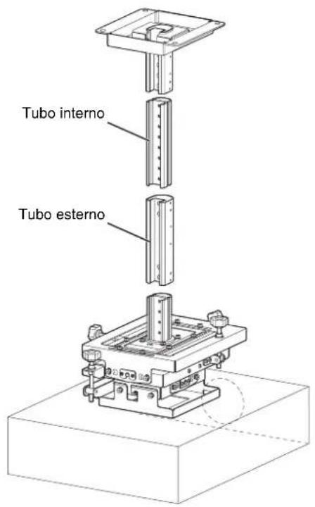
Attenzione
7
flowchart
graph TD
    A["Step A: Square with upward arrow"] --> B["Step B: Rectangular prism with dashed lines and arrows"]
    B --> C["Step C: Inverted rectangle with left-pointing arrows"]
    C --> D["Step D: Solid rectangle with left-pointing arrows"]
    D --> E["Step E: Solid rectangle with right-pointing arrows"]
Attenzione
natural_image
Technical line drawing of a mechanical assembly with mounting flanges and a central component (no text or symbols)调整支架 (1)

natural_image
Technical line drawing of a mechanical assembly with mounting flanges and a central cylindrical component (no text or symbols)投影机安装支架 (1)
natural_image
Isometric line drawing of a mechanical housing or bracket with mounting flanges (no text or symbols)延长管 (外管) (1)
延长管 (内管) (1)
接线盖 (用于内管) (4)
接线盖 (用于外管) (4)

张紧线支架 (2)

固定电线 (1)
电缆夹 (2)
BSW 5 × 12 螺丝 (3)

K6 × 12 螺丝 (6)

M6 × 16 螺栓 (4)

P4 × 6 螺丝 (6)

P5 × 12 螺丝 (6)

PSW 4 × 10 螺丝 (4)

安装手册 (本文档) (1)
注意
natural_image
Technical diagram of a mechanical assembly with mounting holes and a central cylindrical component (no text or symbols)natural_image
Technical diagram of a mechanical assembly with labeled dimension A (no text or symbols beyond label)如果使用延长管
可使用附带的延长管增加高度调整范围。
natural_image
Technical line drawing of a mechanical assembly with no visible text or symbols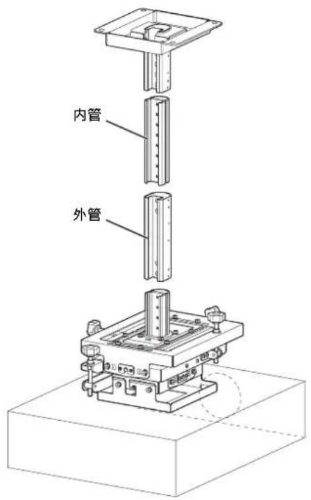
提示
flowchart
graph TD
    A["Step A: Square with upward arrow"] --> B["Step B: Rectangular prism with dashed lines and arrows"]
    B --> C["Step C: Inverted rectangle with left-pointing arrow"]
    C --> D["Step D: Solid rectangle with left-pointing arrow"]
    D --> E["Step E: Left-Right rectangle with right-pointing arrow"]
提示
natural_image
Isometric technical drawing of a mechanical assembly with mounting flanges and a central component (no text or symbols)natural_image
Technical line drawing of a mechanical assembly with mounting flanges and a central cylindrical component (no text or symbols)natural_image
Isometric line drawing of a rectangular electronic component with mounting brackets (no text or symbols)Перед креплением
natural_image
Technical diagram of a mechanical assembly with mounting holes and a central cylindrical component (no text or symbols)natural_image
Technical line drawing of an electronic device with internal components and a close-up inset showing internal structure (no text or symbols)flowchart
graph TD
    A["Step A: Square with upward arrow"] --> B["Step B: Rectangular prism with dashed lines and arrows"]
    B --> C["Step C: Inverted rectangle with bidirectional arrows"]
    C --> D["Step D: Solid rectangle with bidirectional arrows"]
    D --> E["Step E: Solid rectangle with bidirectional arrows"]
Совет


- Projector Suspension Support
- 日本語
- ご注意
- 参考
- For customers
- For dealers
- For the customers in the U.S.A.
- For the customers in Canada
- For the customers in Europe
- For the customers in Korea
- Table of Contents
- Supplied Parts
- Note
- Mounting Configuration
- Top View
- Front View
- Configuration when using VPLL-3003 Projection Lens
- Projection distance calculation formulas
- Lens shift
- Before Attaching
- Attaching to the Ceiling
- Assembling the Ceiling Mounting Bracket
- To adjust the height
- If not using an extension pipe
- If using an extension pipe
- Tip
- Attaching the Ceiling Mounting Bracket to the Ceiling
- Attaching the Projector Mounting Bracket
- Attaching the Projector to the Adjustment Bracket
- Attaching the Fall Prevention Wire
- Attaching the Wiring Covers
- Adjusting the Angle and Position
- Adjustment procedure
- A) Adjusting the horizontal rotation
- B) Adjusting the left/right tilt
- C) Adjusting the up/down tilt
- D) Adjusting the front/back position
- E) Adjusting the left/right position
- Attaching the Brackets for Tension Wires
- Notes
- Typical Ceiling Attachment
- Caution
- Specifications
- External dimensions
- Side view
- Français
- ATTENTION
- Avant la fixation
- Consejo
- 7
- Vor dem Befestigen
- Prima del montaggio
- Attenzione
- 注意
- 如果使用延长管
- 提示
- Перед креплением
Brand : SONY
Model : PSS-650
Category : Projector Accessory