
LMP-H400 - Projector Accessory SONY - Free user manual and instructions
Find the device manual for free LMP-H400 SONY in PDF.

| Product Type | Replacement projector lamp with air filter |
| Brand | Sony |
| Model | LMP-H400 |
| Dimensions (L × H × D) | 285.6 mm × 142.1 mm × 141.1 mm |
| Weight | 2.9 kg (6 lb 6 oz) |
| Lamp Type | High-pressure xenon lamp |
| Included Accessories | Instruction manual (1), Air filter (1) |
| Compatibility | Compatible Sony projectors (check projector manual) |
| Lamp Replacement | Requires a Phillips screwdriver with shaft ≥ 130 mm |
| Air Filter Replacement | Must be replaced at the same time as the lamp |
| Safety | Allow at least 1 hour to cool before replacement; depressurize gas before disassembly |
| Installation Instructions | Detailed in the manual; follow depressurization and fastening steps |
| Maintenance | Wipe fingerprints on the lens with a soft cloth |
Frequently Asked Questions - LMP-H400 SONY
User questions about LMP-H400 SONY
0 question about this device. Answer the ones you know or ask your own.
Ask a new question about this device
Download the instructions for your Projector Accessory in PDF format for free! Find your manual LMP-H400 - SONY and take your electronic device back in hand. On this page are published all the documents necessary for the use of your device. LMP-H400 by SONY.
USER MANUAL LMP-H400 SONY
Operating Instructions GB
Mode d'emploi FR
natural_image
Diagram of a computer monitor with screwdriver inserted, showing internal components and a scroll wheel (no text or symbols)ご注意
バルブキャップ
ご注意
natural_image
Technical line drawing of a car interior showing a screwdriver inserted into the intake compartment (no text or symbols present)natural_image
Line drawing of a computer case with a hand inserting a fan into the case (no text or symbols)ご注意
natural_image
Technical diagram of a car interior showing screwdriver and gear assembly (no text or labels)natural_image
Line drawing of a computer monitor with a screwdriver inserted, showing internal components and a scroll wheel (no text or symbols)11トップカバーを閉める。
natural_image
Technical line drawing of a device casing with internal compartments and a mesh vent (no text or symbols)natural_image
Technical line drawing of a projector with an arrow indicating the component (no text or symbols present)About the Projector Lamp ...... 2
Replacing the Projector Lamp ..... 2
Specifications 5
Air Filter 5
About the Air Filter 5
Replacing the Air Filter 5
Projector Lamp
About the Projector Lamp
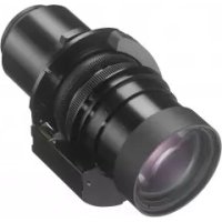
The LMP-H400 Projector Lamp is designed for use with the Sony projector.
Be sure to confirm that this lamp is usable with your projector before using it by reading the Operating Instructions supplied with the projector.
Also, the air filter is supplied with the LMP-H400 Projector Lamp. When you replace the lamp, it is also time to replace the air filter. Whenever you replace the lamp, be sure to replace the air filter with a new one.
For detailed information on how to replace the filter, see “Air Filter” on page 5.
Caution
- The lamp remains hot after the projector is turned off. If you touch the lamp, you may burn your fingers. When you replace the lamp, turn off the projector, then unplug the power cord. Wait for at least an hour for the lamp to cool.
- Do not touch the surface of the lens. If you touch it, wipe off the fingerprints with a soft cloth.
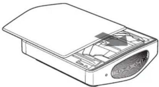
Replacing the Projector Lamp
The illustrations below show the case of replacing the lamp with the projector installed on the floor or desk.
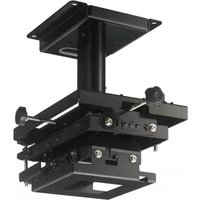
Pay special attention to replacing the lamp when the projector is installed on the ceiling.
1 Turn off the projector and unplug the AC power cord.
2 Place a protective sheet (cloth) beneath the projector.
Note
Be sure that the projector is placed on a stable surface.
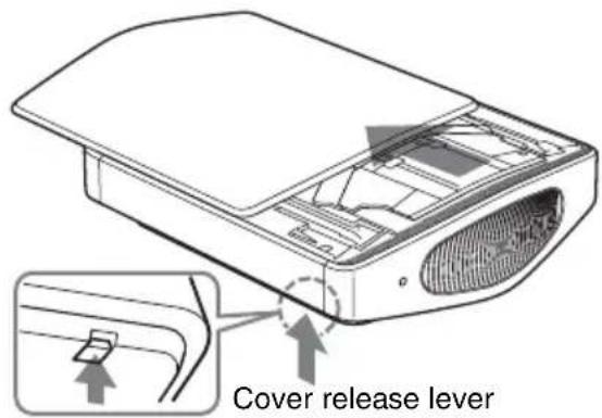
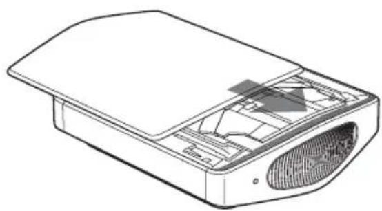
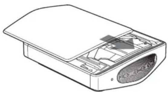
3 While holding up the cover release lever on the right, slide the top cover until it stops.
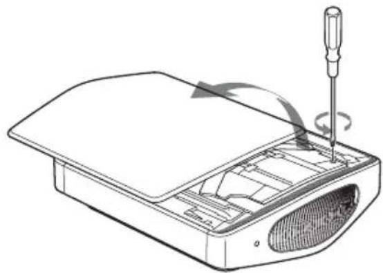
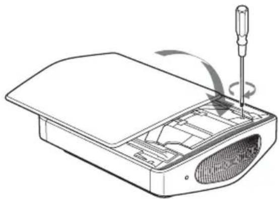
4 Loosen the screw on the lamp cover with a Philips screwdriver, and then open the lamp cover.
natural_image
Diagram of a computer monitor with screwdriver inserted, showing internal components and scroll wheel (no text or symbols)Note
Be sure to use a Philips screwdriver with a shaft length of 130 mm (5 ^1 /8 inches) or more when replacing a projector lamp.
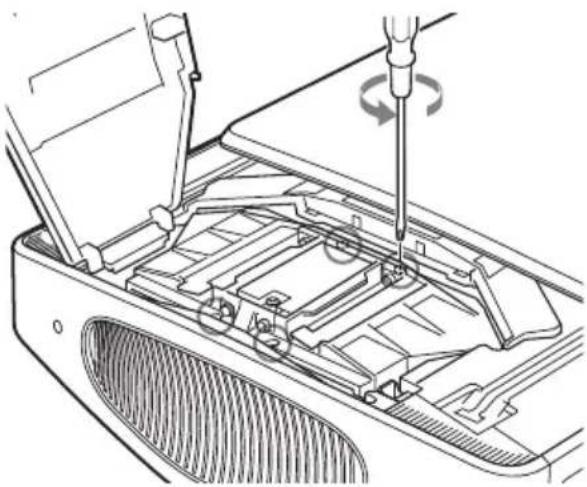
5 Remove the valve cap (①), then turn the gas releasing valve fully clockwise, using a Philips screwdriver (②).

Note
Turn the gas releasing valve clockwise until a hissing sound comes out from the valve.
After this hissing sound stops, go to the next step.
Xenon gas is encapsulated under high pressure inside of the lamp. This xenon gas is odorless and halmless. However, if you drop the lamp or strike it without releasing gas, the lamp may burst. This may result in an injury.
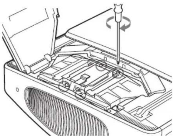
6 Loosen the four screws on the lamp unit with a Philips screwdriver.
natural_image
Technical line drawing of a car interior showing a screwdriver inserted into the engine compartment (no text or symbols present)7 Hold the lamp unit with your hand, and then, pushing the lamp release lever toward the arrow direction (toward the right), pull the lamp unit straight out.
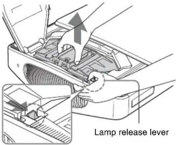
Note
Hold the lamp unit tightly so that you do not drop it, because it is heavy (approx. 2.9 kg (6 lb 6 oz)). Dropping the lamp may result in an injury or a breakdown of the projector.
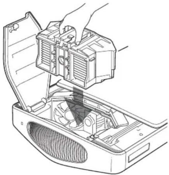
8 Insert the new lamp unit straight in all the way until it is securely in place and you hear it click.
natural_image
Line drawing of a hand inserting a fan into a computer case (no text or symbols)Notes
- Insert the new lamp unit while holding it tightly, because it is heavy (approx. 2.9 kg (6 lb 6 oz)). Dropping the lamp may result in an injury.
- Be careful not to touch the fan or optical block inside the unit.
- Confirm that the lamp release lever has returned to its original position. If not, the projector will not turn on.
9 Tighten the four screws loosened in step 6 to secure the lamp unit to the projector.
natural_image
Technical line drawing of a car interior showing screwdriver and fan components (no text or symbols)10Tighten the screw loosened in step 4 to close the lamp cover.
natural_image
Diagram of a computer monitor with a screwdriver inserted, showing internal components and a scroll wheel (no text or symbols)11 Close the top cover.
natural_image
Technical line drawing of a device casing with internal components and ventilation duct (no text or symbols)12Connect the power cord and set the projector to standby mode.
Confirm that the ON/STANDBY indicator is lit in red.
13Pointing the remote control at the projector, press the following buttons on the remote control in the following order for less than five seconds each: RESET, ←, →, ENTER.
Caution
Do not put your hands into the lamp replacement slot, and do not allow any liquid or other objects into the slot to avoid electrical shock or fire.
Notes
- The projector will not turn on unless the lamp is securely installed in place.
- The projector will not turn on unless the top cover and the lamp cover are securely closed.
Specifications
Dimensions 285.6 mm × 142.1 mm × 141.1 mm (11 ^1/4 × 5 ^5/8 × 5 ^5/_8 inches) (w/h/d)
Mass 2.9 kg (6 lb 6 oz)
Supplied accessories
Operating Instructions (1)
Air Filter
About the Air Filter
Whenever you replace the lamp, be sure to replace the air filter with a new one immediately.
Replacing the Air Filter
Note
When removing the air filter from the projector, be careful that no dust or object gets into the inside of the projector.
The illustrations below show the case of replacing the air filter with the projector installed on the floor or desk.
Pay special attention to replacing the air filter when the projector is installed on the ceiling.
1 Turn the power off and unplug the power cord.
2 Place a protective sheet (cloth) beneath the projector and turn the projector over.
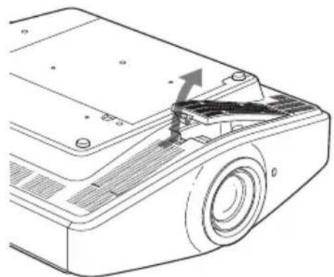
3 Remove the filter holder.
natural_image
Diagram of a projector with an arrow indicating the blade and handle (no text or symbols present)When the air filter cover has been attached onto the projector because it is installed on the ceiling, remove this air filter cover before removing the filter holder.
4 Remove the air filter.
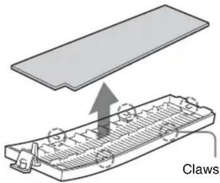
5 Attach the new air filter so that it fits into the each claws (5 positions) on the filter holder.
6 Attach the filter holder.
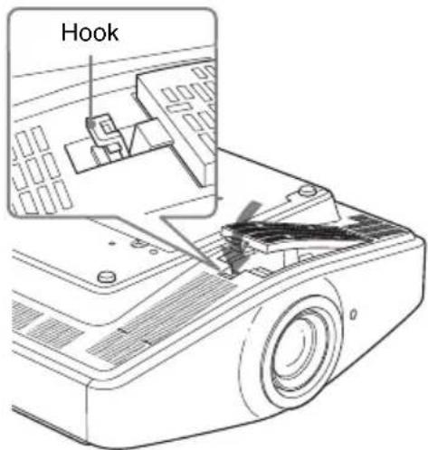
Note
Attach the filter holder securely by pressing on the hook until a click is heard. The projector will not turn on unless the filter holder is securely closed.
Table des matières
natural_image
Diagram of a computer monitor with screwdriver inserted, showing internal components and a scroll wheel (no text or symbols)Remarque
Capuchon de vanne
Remarque
natural_image
Technical line drawing of a car interior showing a screwdriver inserted into the engine compartment (no text or symbols present)natural_image
Line drawing of a refrigerator interior showing the handle, fan, and ventilation system (no text or symbols)Remarques
natural_image
Technical line drawing of a car interior showing screwdriver and valve assembly (no text or symbols)natural_image
Line drawing of a computer monitor with a screwdriver inserted, showing internal components and a scroll wheel (no text or symbols)natural_image
Technical line drawing of a device casing with internal components and a textured interior (no text or symbols)natural_image
Diagram of a projector with an arrow indicating the blade and handle (no text or symbols present)natural_image
Diagram showing a griffing device with internal components and an upward arrow indicating motion (no text or symbols)natural_image
Diagram of a computer monitor with screwdriver inserted, showing internal components and a scroll wheel (no text or symbols)Nota
Tapa de la válvula
Nota
natural_image
Technical line drawing of a car interior with screwdriver and ventilation slots (no text or symbols)natural_image
Line drawing of a hand installing or adjusting a device into a computer case, showing internal components like fan and ventilation (no text or symbols)Notas
natural_image
Technical line drawing of a car interior showing screwdriver and valve assembly (no text or symbols)natural_image
Line drawing of a computer monitor with a screwdriver inserted, showing internal components and a scroll wheel (no text or symbols)natural_image
Technical line drawing of a device casing with internal components and a textured interior (no text or symbols)natural_image
Technical line drawing of a projector with an arrow indicating the blade (no text or symbols present)natural_image
Diagram of a computer monitor with a screwdriver inserted, showing internal components and a scroll wheel (no text or symbols)Hinweis
natural_image
Technical diagram of a car interior showing a screwdriver inserted into the engine compartment with a gear shift (no text or labels)natural_image
Line drawing of a hand opening a computer case with a fan inside, showing internal components (no text or symbols)Hinweise
natural_image
Technical diagram of a car interior showing screwdriver and tool (no text or labels)natural_image
Line drawing of a computer monitor with a screwdriver inserted, showing internal components and a scroll wheel (no text or symbols)natural_image
Technical line drawing of a device casing with internal components and a textured base (no text or symbols)natural_image
Line drawing of a projector with an arrow indicating the blade and handle (no text or symbols)natural_image
Diagram of a device with a flat panel and a grid-like structure, labeled 'Klauen' (no text or symbols on the diagram itself)natural_image
Diagram of a computer monitor with screwdriver inserted, showing internal components and a scroll wheel (no text or symbols)Nota
natural_image
Technical line drawing of a car interior showing a screwdriver inserted into the engine compartment (no text or symbols present)natural_image
Line drawing of a computer motherboard showing fan assembly and ventilation slots (no text or symbols)Note
natural_image
Technical line drawing of a car interior showing screwdriver and valve assembly (no text or symbols)natural_image
Diagram of a computer monitor with a screwdriver inserted, showing internal components and a scroll wheel (no text or symbols)natural_image
Technical line drawing of a device casing with internal components and ventilation duct (no text or symbols)natural_image
Technical line drawing of a projector with an arrow indicating the blade (no text or symbols present)natural_image
Diagram of a computer monitor with screwdriver inserted, showing internal components and a scroll wheel (no text or symbols)注
阀盖
注
natural_image
Technical line drawing of a car interior showing a screwdriver inserted into the engine compartment (no text or symbols present)natural_image
Line drawing of a refrigerator interior showing the handle, fan, and ventilation system (no text or symbols)注
natural_image
Technical line drawing of a car interior showing screwdriver and valve assembly (no text or symbols)natural_image
Diagram of a computer monitor with a screwdriver inserted, showing internal components and a scroll wheel (no text or symbols)11关上顶盖。
natural_image
Technical line drawing of a device casing with internal components and a textured base (no text or symbols)natural_image
Technical line drawing of a projector module with an arrow indicating the component (no text or symbols present)

Brand : SONY
Model : LMP-H400
Category : Projector Accessory