
FreshAir HDE - Air Conditioning DOMETIC - Free user manual and instructions
Find the device manual for free FreshAir HDE DOMETIC in PDF.

| Product type | Roof air conditioner |
| Brand | Dometic |
| Model | FreshAir HDE |
| Dimensions (L x W x H) | 766 x 537 x 213 mm |
| Weight | Approx. 33 kg |
| Supply voltages | 12 V, 24 V, 48 V, 80 V depending on variant |
| Voltage range (48 V) | 38 – 58 V |
| Voltage range (80 V) | 65 – 95 V |
| Max power consumption | 90 A (12 V), 60 A (24 V), 30 A (48 V), 20 A (80 V) |
| Minimum generator power | 100 A (12 V), 90 A (24 V) |
| Cooling capacity | 2200 W (12 V), 2800 W (24 V), 3300 W (48/80 V) |
| Airflow | 400 m³/h |
| Refrigerant | R-134a, pre-filled |
| Compressor | Electric with inverter technology |
| Use | Cooling and air circulation for vehicle cabin |
| Recommended cabin size | 2 – 3 m³ |
| Main functions | Cooling, ventilation, temperature and fan speed adjustment |
| Maintenance | Annual dust filter change, check of fastenings and sealing |
| Cleaning | With a damp cloth; do not use high-pressure cleaner |
| Safety | Do not use if damaged; outdoor temperature >0°C; do not block grilles |
| Installation | Must be carried out by a specialist company; tightening torque 8 Nm; battery protection 60 A |
| Warranty | Legal warranty; attach invoice and defect description |
Frequently Asked Questions - FreshAir HDE DOMETIC
User questions about FreshAir HDE DOMETIC
0 question about this device. Answer the ones you know or ask your own.
Ask a new question about this device
Download the instructions for your Air Conditioning in PDF format for free! Find your manual FreshAir HDE - DOMETIC and take your electronic device back in hand. On this page are published all the documents necessary for the use of your device. FreshAir HDE by DOMETIC.
USER MANUAL FreshAir HDE DOMETIC
natural_image
Technical line drawing of a white industrial fan or vent system with two black fans and mounting brackets (no text or symbols)FreshAir HDE
DE 9 Heavy Duty Dachklimaanlage
EN 23 Heavy duty air conditioning roof unit
Installation and Operating Manual
NL 77 Heavy duty dakairco
natural_image
Technical illustration of a vehicle's air conditioning unit with two fans and control panel (no text or symbols)3
4
natural_image
Technical illustration of a vehicle cabin interior showing dashboard, steering wheel, and structural frame (no text or symbols)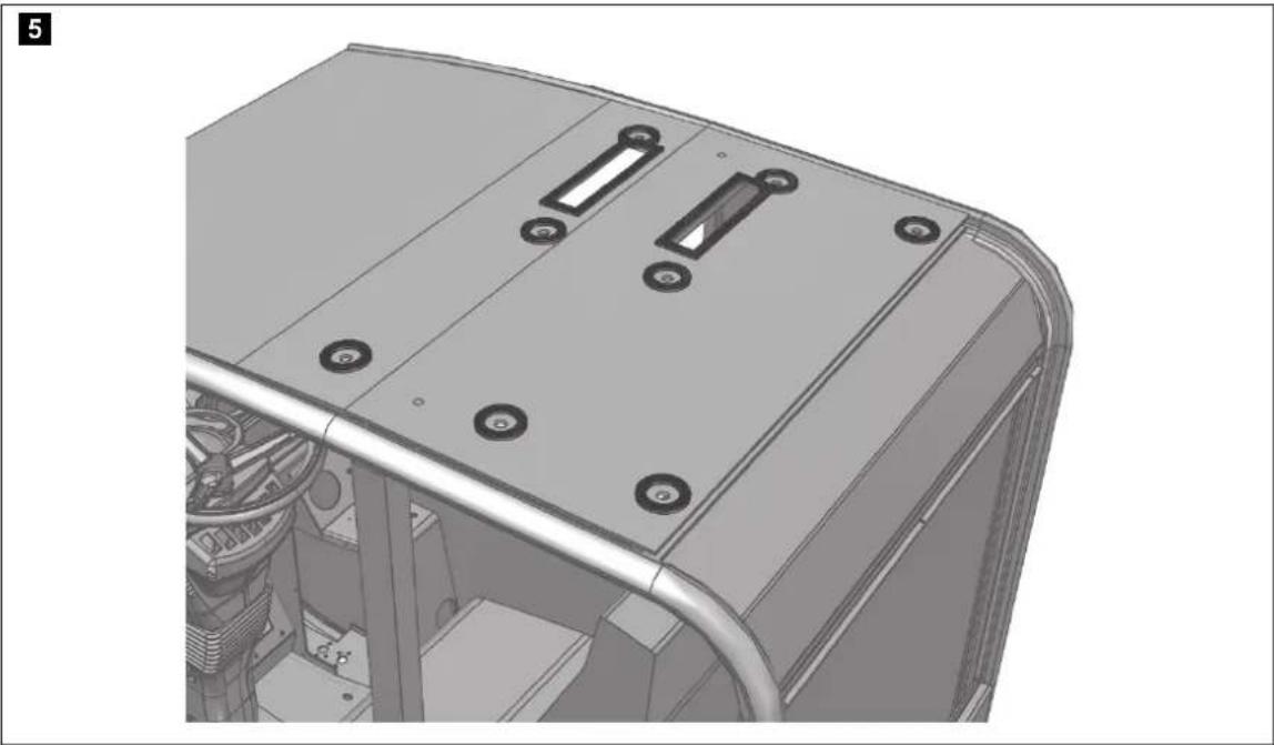
natural_image
3D CAD model of a vehicle chassis with mounting holes and control panel (no text or symbols visible)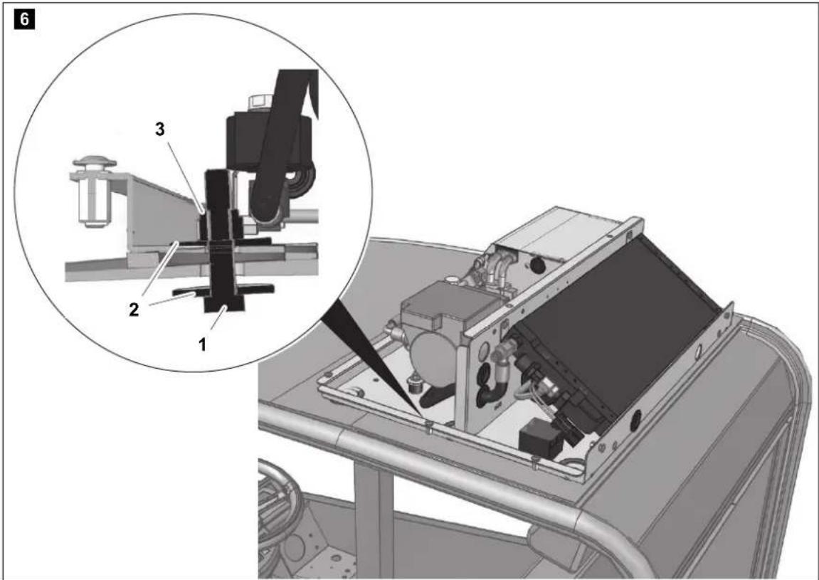
13
Inhaltsverzeichnis
6 Installation ....14
5 Lieferumfang....14 6 Installation....14
1 Symbols and formats....24
2 Safety instructions....24
2.1 Using the device 25
2.1 Using the device 25
2.2 Handling electrical cables 26
2.1 Using the device 25
2.2 Handling electrical cables 26
3 Conventions in this manual....27
3.1 General information on the installation manual 27
3.2 Target Group 27
3.1 General information on the installation manual ..... 27 3.2 Target Group ..... 27
4 Intended use....27
4 Intended use....27
5 Scope of delivery .....27
5 Scope of delivery .....27
6 Installation 28
6.1 Notes on installation 28
6.2 Steps for installation ..... 29
6.1 Notes on installation 28
6.2 Steps for installation 29
6.2.1 Checking installation conditions 29
6.2.2 Preparing the unit fastening 30
6.2.3 Attaching the seal 30
6.2.4 Installing the unit on the cab 31
6.2.5 Connecting electrically 31
6.2.6 Attaching ventilation panel 32
6.2.1 Checking installation conditions 29
6.2.2 Preparing the unit fastening 30
6.2.3 Attaching the seal 30
6.2.4 Installing the unit on the cab 31
6.2.5 Connecting electrically 31
6.2.6 Attaching ventilation panel 32
7 Operating ....33
7 Operating ....33
8 Maintenance ....33
8 Maintenance ....33
9 Care....34
9 Care....34
10 Guarantee ....34
10 Guarantee ....34
11 Disposal ....34
11 Disposal ....34
12 Technical data ....35
1 Symbols and formats

WARNING!
Safety instruction: Failure to observe this instruction can cause fatal or serious injury.

CAUTION!
Safety instruction: Failure to observe this instruction can lead to injury.

NOTICE!
Failure to observe this instruction can cause material damage and impair the function of the product.

NOTE
Supplementary information for operating the product.
▶ Action: This symbol indicates that action is required on your part. The required action is described step-by-step.
√This symbol describes the result of an action.
Fig. 1 5, page 3: This refers to an element in an illustration. In this case, item 5 in figure 1 on page 3.
2 Safety instructions
You must read the entire manual thoroughly and carefully.
We can only guarantee the reliability of the air conditioning roof unit if the instructions are adhered to. The same applies to the prevention of injury and damage to property.
The manufacturer accepts no liability for damage in the following cases:
● Faulty assembly or connection
● Damage to the product resulting from mechanical influences and excess voltage
- Alterations to the product without express permission from the manufacturer
- Use for purposes other than those described in the operating manual
2.1 Using the device
- The travel range of superstructures such as telescopic arms, booms, side forks and other vehicle attachments must not be restricted.
- Only use the air conditioning roof unit for the purpose specified by the manufacturer and do not make any alterations or structural changes to the device.
- Do not use the air conditioning roof unit if it is visibly damaged.
- The air conditioning roof unit must be installed safely so that it cannot tip over or fall down.
- Make sure the air conditioning roof unit is protected from overturning or falling parts.
- Installation, maintenance and repair work may only be carried out by qualified personnel from a specialist company who are familiar with the risks involved and the relevant regulations.
- Do not use the air conditioning roof unit near flammable fluids and gases.
- Do not operate the air conditioning roof unit if the ambient temperature is below 0 °C.
- Do not undo the upper cover of the air conditioning roof unit in the event of a fire. Use approved extinguishing agents instead. Do not use water to extinguish fires.
- Please inquire from your vehicle manufacturer whether the height entered in your vehicle documentation needs to be altered due to the installation of the air conditioning roof unit (height 213 mm).
- Disconnect all power supply lines when working on the air conditioning roof unit (cleaning, maintenance, etc).
2.2 Handling electrical cables
- Use cable ducts to lay cables through walls with sharp edges.
- Complete the wiring so that damage from sharp edged vehicle components is avoided.
- Do not lay loose or bent cables next to electrically conductive materials (metal).
- Do not pull on the cables.
- Attach and lay the cables in such a manner that they cannot be tripped over or damaged.
- The electrical power supply may only be connected by a specialist workshop.
● Fit a fuse of 60 A directly on the battery connection.
- Never lay power supply lines (battery leads) in the vicinity of signal or control cables.
- Lay the electric cables so that they are a distance of at least 15 mm away from rotating parts and at least 150 mm away from parts of the vehicle which become very hot.
- Attach the cable set using the supplied cable binders.
- Join the compact plug connections so that snap-in points are fixed.
- Protect the plug connections in those areas where there is a strong risk of splashing (engine compartment, underbody) with additional protective wax spray, insulating tape or similar.
3 Conventions in this manual
3.1 General information on the installation manual
This installation manual contains the essential information and instructions for installing the air conditioning roof unit. The information contained is orientated towards the company installing the air conditioning roof unit.
The following instructions are intended to help you properly use the installation manual:
- The installation manual is part of the scope of delivery and should be stored carefully.
- The installation manual provides you with important information on the installation of the device and can also be used as a reference material in the event of repairs.
- The manufacturer assumes no liability for non-observance of this installation manual. Any claims are excluded in this case.
3.2 Target Group
These installation instructions are aimed at installers who have professional expertise and experience in the area of vehicle air conditioning.
These are not a substitute for training in vehicle air conditioning
4 Intended use
The WAECO FreshAir HDE air conditioning roof unit ensures rapid cooling of the vehicle cabin and a pleasant climate.
The air conditioning roof unit runs in circulation mode. For this reason, the cabin door and other existing openings must be closed during operation.
The air conditioning roof unit must not be running if the vehicle must be used for work which needs the cabin door open.
5 Scope of delivery
Part designation Quantity Item no.
Installation manual 1 4445101323
Air conditioning roof unit 1
Ventilation plate with control panel 1
6 l n s t a l l a t

NOTICE!
The air conditioning roof unit may only be installed by qualified personnel from a specialist company. The following information is intended for technicians who are familiar with the guidelines and safety precautions to be applied.
6.1 Notes on installation
These installation instructions must be read completely prior to the installation of the air conditioning roof unit.
The following tips and instructions must be observed while installing the air conditioning roof unit:

WARNING!
Ensure that all electrical components are electrically discharged before carrying out work on them.
- Always check whether any vehicle components could be damaged or their operation impaired by the unit before installing the air conditioning roof unit. You can use fig. 1, page 3 to check the dimensions of the installed unit.
● The supplied assembly parts must not be modified during installation. - The ventilation slots (grill) may not be covered (minimum distance from other attachment parts: 10 cm).
- For installation and repair work, adhere to the corresponding rules of technology.
- When installing the system and making the electrical connections, observe the guidelines from the body manufacturer.
- Use appropriate tools for each step of the installation.
- Prior to and during drilling, note the location of existing cable harnesses, cables and other components.

WARNING!
Before installing the air conditioning roof unit, the power supply at the battery of the vehicle must be disconnected. Non-observance of this regulation can result in danger of electrocution.

CAUTION!
Improper installation of the air conditioning roof unit can result in irreparable damage to the device and put the safety of the user at risk. The manufacturer will not be held liable for claims if the air conditioning roof unit is not installed according to this installation manual. That applies to malfunctions and the safety of the air conditioning roof unit, in particular to injuries and damage to property.
6.2 Steps for installation

NOTICE!
- The manufacturer only assumes liability for parts included in the scope of delivery. The validity of the warranty expires if the device is installed together with third-party parts.
- Check whether the roof of the vehicle is able to support the weight of a person before climbing onto it. Ask the vehicle manufacturer about the permitted roof loads.
- Before installing the air conditioning system on the roof, protect the upper part of the cabin with a cloth or a blanket to prevent any scratches or damages.
6.2.1 Checking installation conditions
Before installation, check (by consulting the manufacturer of the vehicle) whether the construction is designed for the static weight and the loads of the air conditioning roof unit when the vehicle is in motion. The manufacturer of the roof air conditioner assumes no liability whatsoever.
Cabins with a sunroof generally have a robust structure in order to bear the weight of the air conditioner.
Where this is not the case, and the structure is not rigid enough to bear the weight of the air conditioner (e.g. fibreglass roofs or for roofs with pre-existing cut-out sections), you must check whether the cabin roof needs to be strengthened.
▶ Check the minimum requirements for the installation of an air conditioning roof unit
- Vehicle voltage
– Power consumption - Generator power
– Size and load bearing capacity of the cabin
▶ Check the output voltage of the three phase generator (14 – 15 V).
▶ Check the efficient functioning of all electrically operated vehicle components.
▶ If deviations are identified, please inform workshop management or the vehicle owner.
6.2.2 Preparing the unit fastening
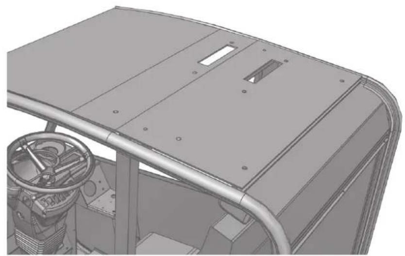
Place the unit on the roof and make sure that the roof area of the cabin is level (fig. 2, page 3).
▶ Check whether the cut-out sections for the air inlet and outlet and the installation of the cover can be completed inside the cabin.
▶ Remove the cover of the air conditioning roof unit.
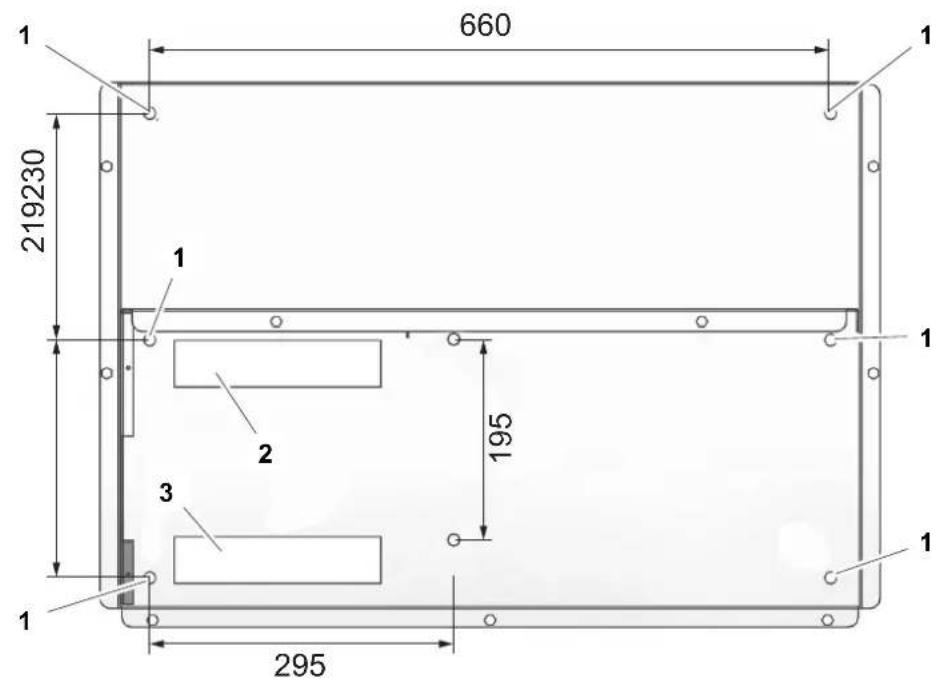
▶ Mark the six fastening holes ∅ 10 mm (fig. 3 1, page 4).
▶ Mark the rectangular opening for the air inlet (fig. 3 2, page 4).
▶ Mark the rectangular opening for the air outlet (fig. 3 3, page 4).

NOTICE!
Check that under the roof plate there are no electric wires, lining or vehicle facilities near the holes.
▶ Perform the holes and the openings (fig. 4, page 4).
▶Protect the holes and the openings with antioxidant.
6.2.3 Attaching the seal

NOTICE!
Ensure that the adhesive surface for the seal between the unit and the cab roof is clean (free of dust, oil, etc.).
▶ Apply sealing or something similar to prevent any water from getting between the holes and the air vents (fig. 5, page 5).
6.2.4 Installing the unit on the cab
▶ Place the unit on the roof so that the holes match (fig. 6, page 5).
▶ Attach the unit with six M8 screws (fig. 6 1, page 5), with twelve washers (fig. 6 2, page 5) and six self-tapping M8 nuts (fig. 6 3, page 5).

NOTICE!
Do not exceed the specified torque under any circumstances. This is the only way to ensure that the thread inserts are not torn out.
▶Tighten the screws with a torque of 8 Nm.
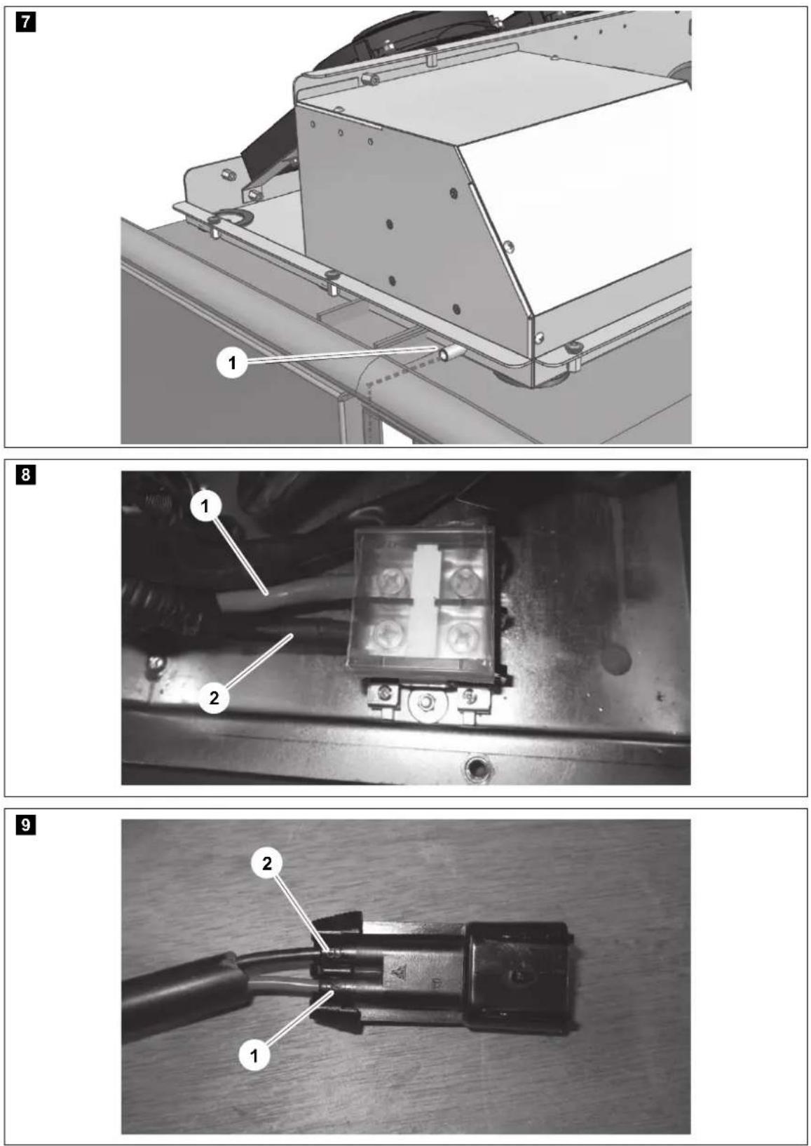
▶ Fasten the condensate drain hose (fig. 7 1, page 6) to the system.
▶ Align the condensate drain hose by turning so that the condensation can drain.
6.2.5 Connecting electrically

WARNING!
- The electrical power supply may only be performed by qualified personnel with specialist knowledge.
- Ensure there is no voltage present on electrically operated components before carrying out work on them.

NOTICE!
● Fit a fuse of 60 A to the connection to the vehicle's power supply.
- The battery must be able to supply the required current and voltage (chapter "Technical data" on page 35).
Connecting inside the air conditioning roof unit (fig. 8, page 6)
▶Select the minimum gauge for the connection cables according to the following table:
| Cable length | Minimum gaugeFor 12 V systems | Minimum gaugeFor systems with24 V, 48 V, 80 V |
| 1 m 16 mm ^2 10 mm ^2 | ||
| 2 m 25 mm ^2 10 mm ^2 | ||
| 3 m 35 mm ^2 16 mm ^2 |
▶ Connect the positive power cable to the red cable of the block (1).
▶ Connect the negative cable to the black cable of the block (2).
Connecting outside the air conditioning roof unit (fig. 9, page 6)
▶Connect the two-pin Metri-Pack sealed 280 plug to:
– Position A (1): positive terminal (red), protected by a 20 A fuse
– Position B (2): negative terminal (black)
Connecting the control panel (fig. 10, page 7)
▶ Connect the 5-pin black plug to the ventilation switch (1).
▶ Connect the 3-pin black plug to the temperature switch (2).
▶ Connect the green wire to the On/Off switch (3).
▶ Connect the red-black wire to On/Off switch (3).
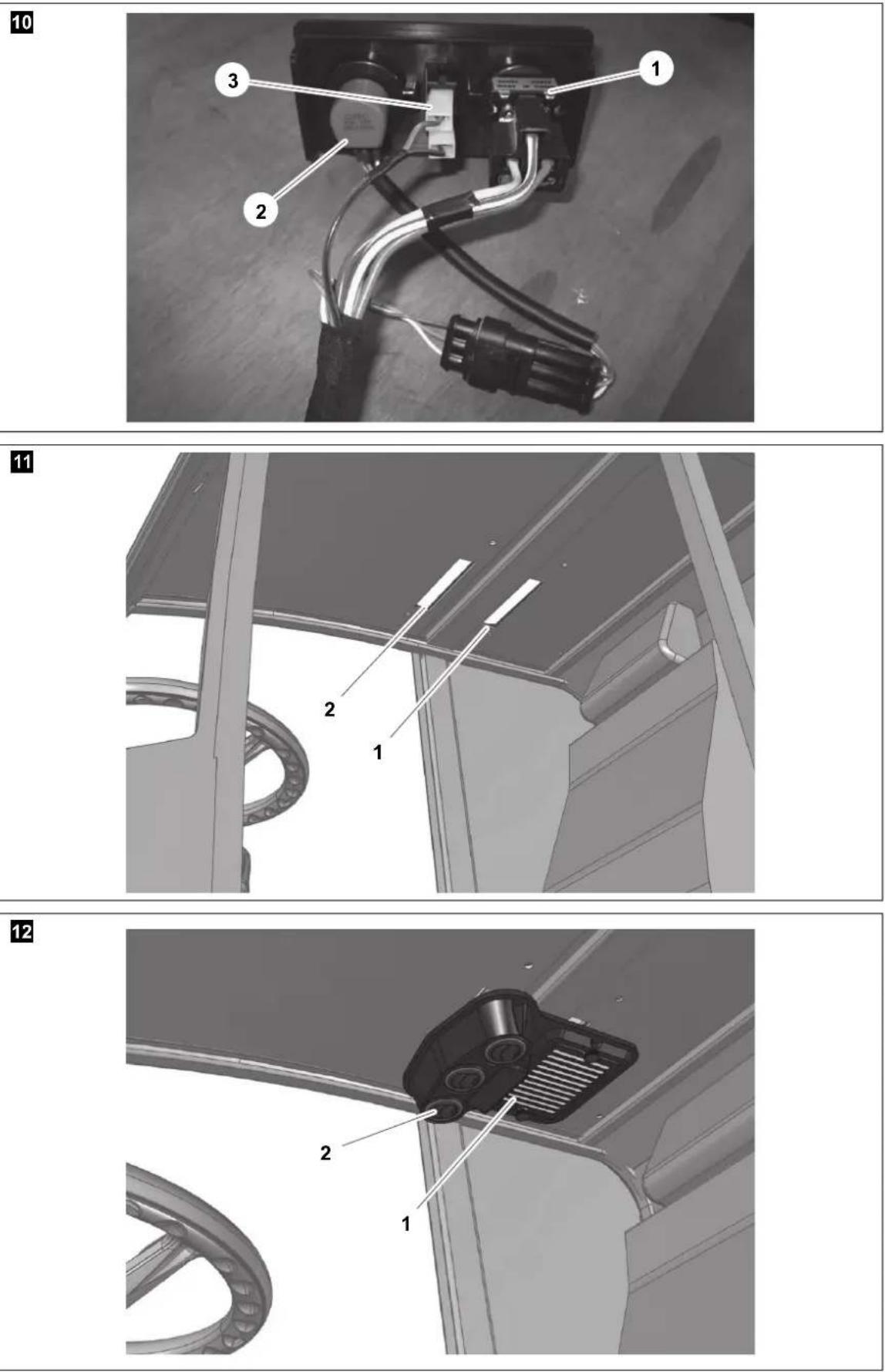
6.2.6 Attaching ventilation panel

NOTICE!
Check prior to installation that there are no electrical cables or hoses between roof and ventilation panel.
▶ Place the ventilation panel in the cabin under the roof (fig. 11, page 7).
Position the ventilation panel so that:
- the air inlet grill is under the air inlet opening (fig. 12 1, page 7) of the air conditioning roof unit
- the three air outlet nozzles are under the air outlet opening (fig. 12 2, page 7) of the air conditioning roof unit

NOTE
The length of the fastening bolts for the ventilation panel depends on the thickness of the lining of the roof interior.
Make sure, before screwing the ventilation plate in place, that the length of the bolts do not interfere with the air conditioning roof unit.
▶ Select fastening bolts (not included in scope of delivery) which are appropriate for the roof thickness and the strength of the bodywork.
▶ Attach the ventilation plate (fig. 12, page 7).
7 Operating

NOTE
The air conditioning roof unit runs in circulation mode. For this reason, the cabin door and other existing openings must be closed during operation.
Do not run the air conditioning roof unit if the vehicle must be used for work which needs the cabin door open.
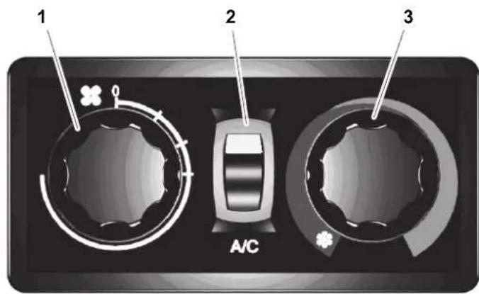
The air conditioning roof unit can be set at the control panel (fig. 13, page 8):
Item Description
| 1 Ventilation switch |
| 2 ON/OFF switch |
| 3 Temperature switch |
Switching on the air conditioner (fig. 13, page 8)
▶ Set the blower step switch (1) to level "1".
▶ Switch on the air conditioning roof unit using the ON/OFF switch (2).
√The green LED lights up.
▶ Use the temperature switch (3) to select the desired temperature.
8 Maintenance
▶Complete maintenance annually
Replace the dryer and coolant when doing so.
▶ Check for the efficient functioning of the air conditioning roof unit.
▶Change the dust filter.
9 C a r e

NOTICE!
- Do not use abrasive cleaning agents or hard objects for cleaning as these can damage the device.
- Do not clean the roof air conditioner with a high-pressure cleaner. Water ingress can damage the roof air conditioner.
▶ Clean the housing of the roof air conditioner and the outlet panel occasionally with a damp cloth.
Remove leaves and other dirt from the ventilation grilles of the roof air conditioner occasionally. Make sure you do not damage the system in the process.
▶Change the dust filter regularly.
▶ Check regularly that all the elements for the roof air conditioner are fastened.
▶ Check regularly that the connection leads are undamaged and secure.
▶ Check regularly that all the through-holes for the roof air conditioner are sealed.
10 Guarantee
The statutory warranty period applies. If the product is defective, please contact the manufacturer's branch in your country (see the back of the instruction manual for the addresses) or your retailer.
For repair and guarantee processing, please include the following documents when you send in the device:
● A copy of the receipt with purchasing date
● A reason for the claim or description of the fault
11 Disposal
- Place the packaging material in the appropriate recycling waste bins wherever possible.
If you wish to finally dispose of the product, ask your local recycling centre or specialist dealer for details about how to do this in accordance with the applicable disposal regulations.
12 Technical data
| Waeco FreshAir HDE | ||||
| Item number: 8881200126 8881200127 8881200128 8881200129 | ||||
| Voltage: | 12 V--- | 24 V--- | 48 V--- | 80 V--- |
| Voltage range: | - | - | 38 – 58 V--- | 65 – 95 V--- |
| Current consumption: | 90 A | 60 A | 30 A | 20 A |
| Minimum generator opwer: | 100 A | 90 A | - | - |
| Cooling capacity: | 2200 W | 2800 W | 3300 W | 3300 W |
| Compressor: | electric | |||
| Inverter technology: | yes | |||
| Air flow: | 400 m^2/h | |||
| Refrigerant: | R-134a | |||
| Pre-charged: | yes | |||
| Model: | Cooling/Circulating air | |||
| C a b s i ze : | 2 - 3 m^3 | |||
| Dimensions (L x B x H): | 766 x 537 x 213 mm | |||
| Weight: | approx. 33 kg | |||
Sommaire
6 Installation....41
6.2.3 Poser le joint 43
6.2.3 Poser le joint

AVIS!
Dometic Australia Pty. Ltd.
1 John Duncan Court
Varsity Lakes QLD 4227
1800 212121
+61 7 55076001
Mail: sales@dometic-waeco.com.au
AUSTRIA
Dometic Austria GmbH
Commercial : info@dometic.fr
SAV/Technique : service@dometic.fr
HONG KONG
WAECO Impex Ltd.
Suites 2207-2211 · 22/F · Tower 1
The Gateway · 25 Canton Road,
Tsim Sha Tsui · Kowloon
+852 24611386
旦 +852 24665553
Mail: info@dometic-waeco.com.hk
HUNGARY
Dometic Plc. Sales Office
Kerékgyártó u. 5.
H-1147 Budapest
+36 1 468 4400
+36 1 468 4401
Dometic Italy S.r.l.
Via Virgilio, 3
I-47100 Forlì
+39 0543 754901
+39 0543 756631
Mail: info@dometic.it
NORWAY
Dometic Norway AS
Skolmar 24
N-3232 Sandefjord
+47 33428450
+47 33428459
Mail: firmapost@waeco.no
POLAND
Dometic Poland Sp. z o.o.
Ul. Puławska 435A
02-801 Warszawa
+48 22 414 32 00
르 +48 22 414 32 01
Mail: info@dometic.pl
RUSSIA
Dometic RUS LLC
Komsomolskaya square 6-1
107140 Moscow
+7 495 780 79 39
+7 495 916 56 53
Mail: info@dometic.ru
SLOVAKIA
Dometic Slovakia Sales Office Bratislava
Nádražná 34/A
SK-900 28 Ivanka pri Dunaji
+421 2 45 529 680
Mail: bratislava@dometic.com
SPAIN
Dometic Spain S.L.
Avda. Sierra del Guadarrama, 16
E-28691 Villanueva de la Cañada
Madrid
+34 902 111 042
+34 900 100 245
Mail: info@dometic.es
SWEDEN
Dometic Scandinavia AB
Gustaf Melins gata 7
Dometic Switzerland AG
Riedackerstrasse 7a
CH-8153 Rümlang (Zürich)
+41 44 8187171
르 +41 44 8187191
Mail: info@dometic-waeco.ch
TAIWAN
WAECO Impex Ltd.
Taipei Office
9F.-10, No. 1180, Zhongzheng Rd.,
Zhonghe Dist., New Taipei City 23586
+886 2 22237225
+886 2 81926742
Mail: marketing@waeco.com.tw
UNITED KINGDOM
Dometic UK Ltd.
Dometic House · The Brewery
Blandford St. Mary
Dorset DT11 9LS
+44 844 626 0133
+44 844 626 0143
Mail: sales@dometic.co.uk
UNITED ARAB EMIRATES
Dometic Middle East FZCO
P. O. Box 17860
S-D 6, Jebel Ali Freezone
Dubai
+971 4 883 3858
+971 4 883 3868
Mail: info@dometic.ae
UNITED STATES OF AMERICA
Dometic Marine Division
2000 N. Andrews Ave. Extension
Pompano Beach, FL 33069 USA
+1 954 973 2477
+1 954 979 4414
Mail: marinesales@dometicusa.com

- FreshAir HDE
- Inhaltsverzeichnis
- Symbols and formats
- WARNING!
- CAUTION!
- NOTICE!
- NOTE
- Safety instructions
- Using the device
- Handling electrical cables
- Conventions in this manual
- General information on the installation manual
- Target Group
- Intended use
- Scope of delivery
- l n s t a l l a t
- Notes on installation
- Steps for installation
- Checking installation conditions
- Preparing the unit fastening
- Attaching the seal
- Installing the unit on the cab
- Connecting electrically
- Connecting inside the air conditioning roof unit (fig. 8, page 6)
- Connecting outside the air conditioning roof unit (fig. 9, page 6)
- Connecting the control panel (fig. 10, page 7)
- Attaching ventilation panel
- Operating
- Switching on the air conditioner (fig. 13, page 8)
- Maintenance
- C a r e
- Guarantee
- Disposal
- Sommaire
- Poser le joint
- AVIS!
- Dometic Australia Pty. Ltd.
- AUSTRIA
- Dometic Austria GmbH
- HONG KONG
- WAECO Impex Ltd.
- HUNGARY
- Dometic Plc. Sales Office
- Dometic Italy S.r.l.
- NORWAY
- Dometic Norway AS
- POLAND
- Dometic Poland Sp. z o.o.
- RUSSIA
- Dometic RUS LLC
- SLOVAKIA
- Dometic Slovakia Sales Office Bratislava
- SPAIN
- Dometic Spain S.L.
- SWEDEN
- Dometic Scandinavia AB
- Dometic Switzerland AG
- TAIWAN
- UNITED KINGDOM
- Dometic UK Ltd.
- UNITED ARAB EMIRATES
- Dometic Middle East FZCO
- UNITED STATES OF AMERICA
- Dometic Marine Division
Brand : DOMETIC
Model : FreshAir HDE
Category : Air Conditioning