IVR 60/30 Sc H ACD - Vacuum Cleaner Kärcher - Free user manual and instructions
Find the device manual for free IVR 60/30 Sc H ACD Kärcher in PDF.

User questions about IVR 60/30 Sc H ACD Kärcher
0 question about this device. Answer the ones you know or ask your own.
Ask a new question about this device
Download the instructions for your Vacuum Cleaner in PDF format for free! Find your manual IVR 60/30 Sc H ACD - Kärcher and take your electronic device back in hand. On this page are published all the documents necessary for the use of your device. IVR 60/30 Sc H ACD by Kärcher.
USER MANUAL IVR 60/30 Sc H ACD Kärcher
The Ground Truth image displays a single, solid horizontal line. According to Rule 2 (UNDERSCORE & LINE RULES), this is a stylistic or background line, not a placeholder underscore. Therefore, the OCR result must ignore it. The provided OCR content is "\_\_\_\_", which consists of four underscores. This is an incorrect interpretation of the line as a placeholder, violating the rule that stylistic lines must be ignored. The OCR has hallucinated text (underscores) where none should exist, violating the rule to ignore such lines. Hence, the OCR result is inconsistent with the Ground Truth.
IVR 60/30 Sc H ACD
IVR 100/30 Sc H ACD
IVR 100/40 Sc H ACD
Deutsch 7
English 21
Français 34
Italiano 49
Español 63
Português 78
Nederlands 92
Türkçe 106
Svenska 118
Suomi 131
Norsk 144
Dansk 156
Eesti 169
Latviešu 181
Lietuviškai 194
Polski 207
Magyar 221
Čeština 235
Slovenčina 248
Slovenščina 261
Româneşte 274
Hrvatski 289
Srpski 302
Ελληνικά 316
Русский 331
Українська 347
Български 363
natural_image
Illustration of an open book with a black arrow indicating rotation (no text or symbols)A
text_image
Technical diagram of a vacuum cleaner with numbered parts and control panel, including gauges and wheels.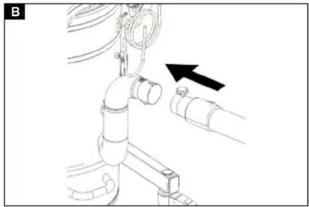
natural_image
Technical diagram of a mechanical assembly with pipes and a directional arrow (no text or symbols)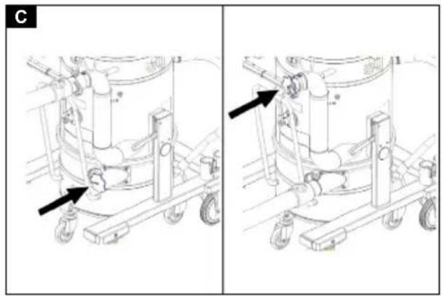
natural_image
Technical line drawing of a mechanical assembly with two views (left and right) showing components like wheels, pipes, and a cylindrical component (no text or symbols present)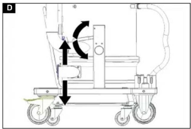
natural_image
Technical line drawing of a mechanical device with wheels and a curved arrow indicating motion (no text or symbols)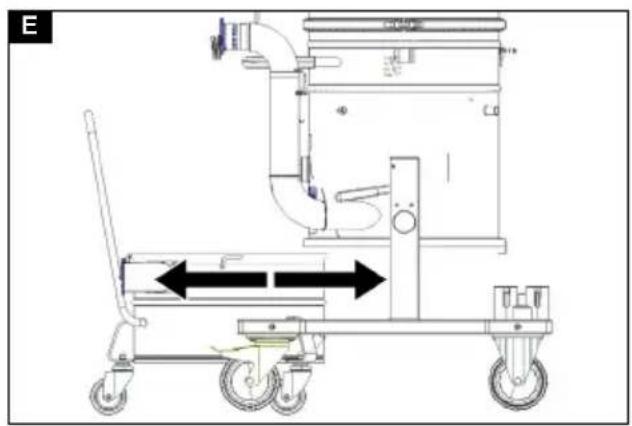
natural_image
Technical line drawing of a mechanical device with wheels and internal components (no text or symbols)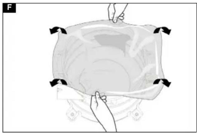
natural_image
Illustration of hands holding a bag with arrows indicating direction (no text or symbols)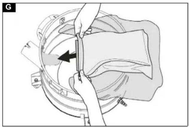
natural_image
Illustration of a hand using a tool to adjust or install a mechanical component, with no visible text or symbols.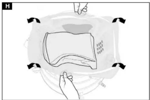
natural_image
Diagram of a hand pressing down on a device with arrows indicating motion (no text or symbols)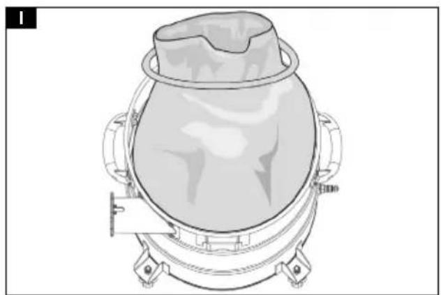
natural_image
Technical line drawing of a mechanical device with a central housing and mounting base (no text or symbols)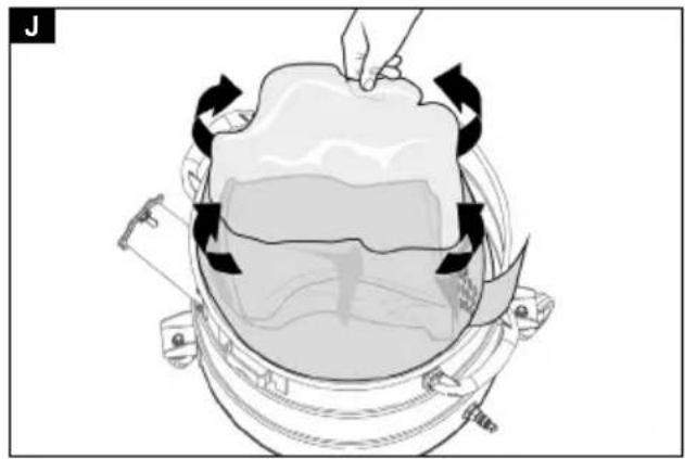
natural_image
Diagram of a mechanical device with arrows indicating motion or force direction (no text or symbols)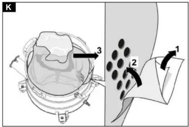
text_image
K 3 2 1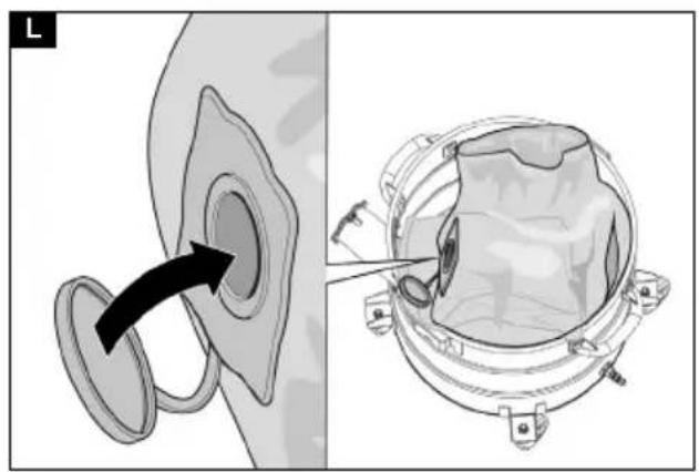
natural_image
Technical illustration of a mechanical component with an arrow indicating direction, showing internal structure and assembly (no text or symbols)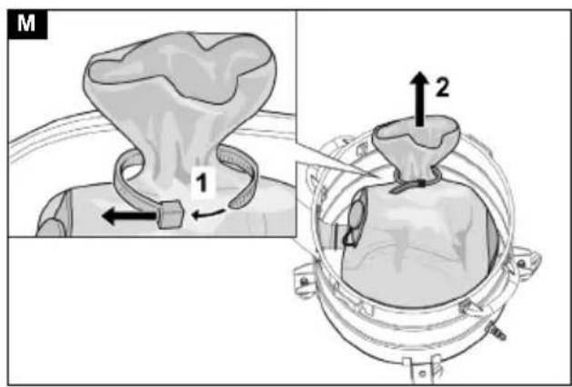
text_image
M 1 2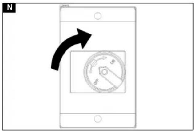
text_image
N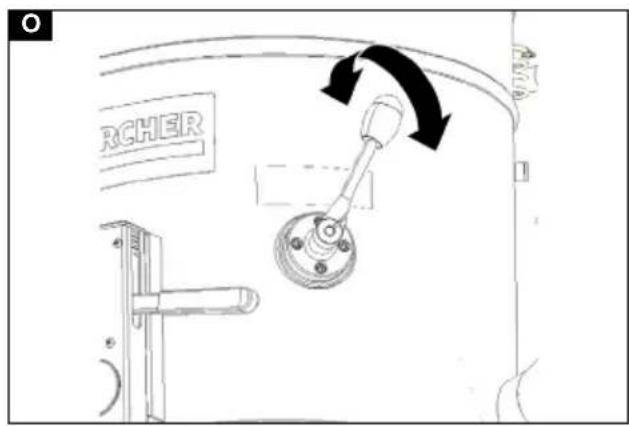
text_image
RCHER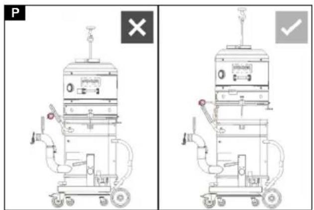
text_image
P × ✓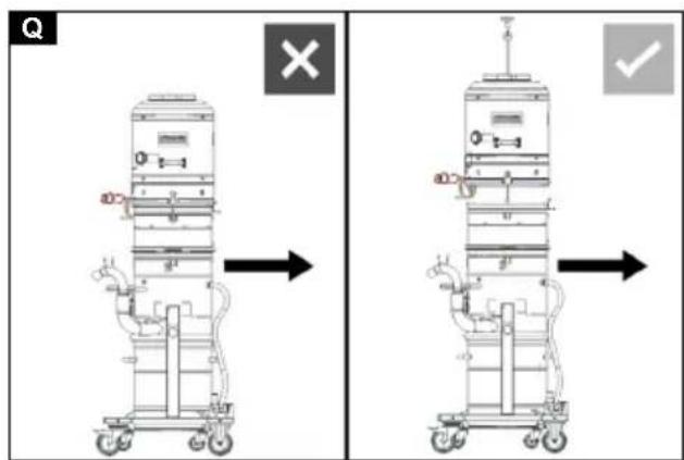
text_image
Technical diagram showing two views of a vertical cylindrical device with labeled components and directional arrows indicating process flow or assembly.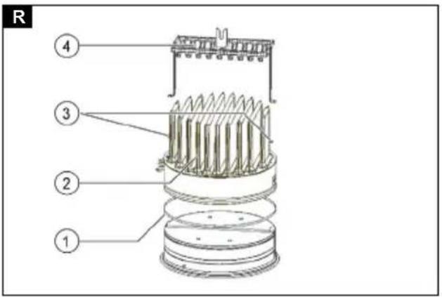
text_image
R ① ② ③ ④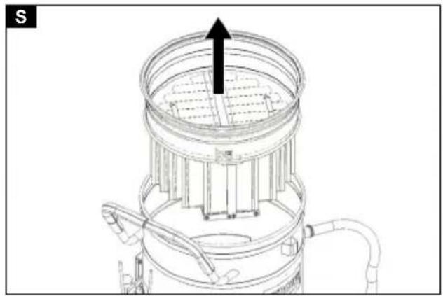
natural_image
Technical line drawing of a mechanical device with a central fan and internal structure, no visible text or symbols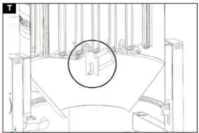
natural_image
Architectural line drawing of a modern building interior with columns and a central circular feature (no text or symbols)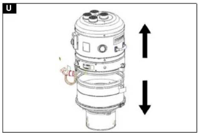
natural_image
Technical line drawing of a mechanical device with two vertical arrows indicating upward and downward motion (no text or symbols present)Inhalt
natural_image
Simple line drawing of a mechanical cart with a large cylindrical component and a black 'X' mark (no text or symbols)73550 Waldstetten (Germany)
Tel.: +49 7171 94888-0
Fax: +49 7171 94888-528
Waldstetten, 23/10/01
Contents
General instructions 21
Safety information 21
Intended use 22
Environmental protection 23
Accessories and spare parts.... 23
Scope of delivery 23
Device description.... 23
Symbols on the device.... 23
Initial startup.... 24
Operation 25
Transport.... 28
Storage 28
Care and maintenance.... 28
Troubleshooting guide...... 31
Disposal 32
Warranty.... 32
Technical data 32
Declaration of Conformity 33
General instructions
Read these original instructions before using your device for the first time, adhere to the instructions contained therein and store them for later reference or subsequent owners.
- Be sure to read the safety instructions no. 5.956-249.0 prior to the initial start-up.
- If the operating instructions and safety instructions are not observed, the device can be damaged and dangers could arise for users and other persons.
- Notify the dealer immediately in the case of shipping damage.
Safety information
Hazard levels
⚠️DANGER
- Indication of an imminent threat of danger that will lead to severe injuries or even death.
⚠ WARNING
- Indication of a potentially dangerous situation that may lead to severe injuries or even death.
△CAUTION
- Indication of a potentially dangerous situation that may lead to minor injuries.
ATTENTION
- Indication of a potentially dangerous situation that may lead to damage to property.
General safety instructions
⚠️ DANGER ● Only trained personnel are permitted to use the device and the substances for which it is to be used, including the safe procedure for disposing of the vacuumed material. ● An air exchange rate L must be present in the room when the exhaust gas is returned into the room. To remain within the required limit values, the volume flow of returned air must be no greater than 50% of the fresh air volume (room volume V_R × air exchange rate L_W ). Without special ventilation measures, the following applies: L_W=1h^-1 . ● This device contains dust that is harmful to your health. Emptying and maintenance, including removal of the dust bag, may only be performed by technical specialists wearing suitable personal protective equipment.
- Do not operate the device without the complete filtration system. Observe the applicable safety instructions for the materials being vacuumed. The simultaneous collection of different combustible dusts in the collection container can lead to fires or explosion.
⚠ WARNING • You must not set up or operate the device in areas where there is a risk of dust or gas explosion. A dust explosive atmosphere inside the device is only allowed in front of the filter. Gas explosive atmospheres are prohibited inside the device. • The device is not suitable for the suctioning or vacuuming of flammable liquids (flammable, easily flammable, highly flammable according to Dangerous Substances Directive 67/548/EEC) (flash point below 55 °C) and mixtures of flammable dusts and liquids. • The device is not suitable for the vacuuming of dusts with extremely low minimum ignition energy (ME <1 mJ), e.g. toner, mesh, aluminium powder, lead acid suitable. • The device is not suitable for sucking up ignition sources
and dusts with a glow temperature ≤ 190 °C. • Every time before use, check whether the equipotential bonding conductors (earthing conductors) are connected. • The device must not be used or stored outdoors in wet conditions. • Apply the parking brake at the steering roller to ensure a secure footing for the device. The device may move uncontrollably if the parking brake is open.
⚠️ CAUTION ● In case of longer breaks in operation and after use, switch off the device at the power switches and unplug the mains plug.
ATTENTION • Only use the device indoors. • Risk of crushing! Wear gloves when removing or installing the suction head, filter inlay or collection container.
- Risk of damage! Never vacuum without a filter or with a damaged filter. ● Wear safety shoes when operating the device. ● Only move the device at walking speed, and to move down a decline, have two workers steady the device as necessary. ● Be careful to ensure that there is no dust spillage when replacing accessories. ● Surface temperatures can rise to 135°C during normal operation. ● Avoid kinking the suction hose unit. ● Carry out a regular visual inspection of the hoses.
Electrical connection
The device may only be connected to an electrical connection which has been set up by a qualified electrician as per IEC 60364. For connected loads see Technical data and type plate.
⚠️DANGER
Danger of electric shock
Danger of death
Avoid damaging the power cables by driving over them or otherwise crushing them, or by jerking them.
Protect the cables from heat, oil and sharp edges.
Check the mains connection of the device for damage every time before operation. Do not operate the device using a damaged cable. Have any damaged cables replaced by a qualified electrician.
Behaviour in the event of an emergency
⚠️DANGER
Risk of injury and damage in the event of a short-circuit or other electrical faults
Danger of electric shock, danger of burns Switch off the device and unplug the mains plug.
Behaviour in case of filter breakage / leakage:
-
Switch off the unit immediately. The unit may not be operated without the fresh water filter.
-
Replace the filter.
Intended use
The device is intended for:
- Wet and dry cleaning of floor and wall surfaces
- Extraction of dry, flammable, deposited dusts hazardous to health; dust class H according to EN 60335-2-69
• Vacuuming of non-explosive substances - Vacuuming of flammable dusts of all dust explosion classes (excluding dusts with a minimum ignition energy ME < 1 mJ)
• Vacuuming of dusts and coarse dirt - Vacuuming of flammable dusts from a zone 22 if the device is installed outside of potentially explosive areas
• Vacuuming moist and liquid substances - Commercial use, e.g. in hotels, schools, hospitals, factories, shops, offices, and rental companies
- Industrial usee.g in storage and production areas
A corresponding Ex device must be used if there is a classified Ex zone at the device installation location.
The device's correct function is only guaranteed when using suction hose nominal widths of DN40 and DN50.
Any other use constitutes improper use.
The device is not suitable for:
- Vacuuming of ignition sources and dusts with a glow temperature ≤ 190 °C
- vacuuming of explosive or equivalent substances as defined in §1 SprengG, explosive steam/air mixtures, as well as Al and Mg dusts
- vacuuming of flammable liquids (flammable, easily flammable, highly flammable according to Dangerous Substances Directive 67/548/EEC) (flash point below 55 °C) and mixtures of flammable dusts and liquids
- vacuuming of magnesium dust or powder
- vacuuming of mixtures of flammable liquids and flammable dust
- Vacuuming of smouldering or hot particles where this could otherwise result in a fire or an explosion
- Connection to a dust-generating machine
Environmental protection

The packing materials can be recy- cled. Please dispose of packaging in accordance with the environmental regulations.

Electrical and electronic devices contain valuable, recyclable materials and often components such as batteries, rechargeable batteries or oil, which - if handled or disposed of incorrectly - can pose a potential danger to human health and the environment. However, these components are required for the correct operation of the device. Devices marked by this symbol are not allowed to be disposed of together with the household rubbish.
Notes on the content materials (REACH)
Current information on content materials can be found at: www.kaercher.de/REACH
Accessories and spare parts
⚠️DANGER
Risk of explosion when used with non-permitted accessories
Only use accessories permitted by the manufacturer and with the Ex label for type 22 usage.
Only use original accessories and original spare parts. They ensure that the appliance will run safely and fault-free.
Information on accessories and spare parts can be found at www.kaercher.com.
Note
No accessories are included in the scope of delivery. The accessories must be ordered separately depending on the application.
Scope of delivery
Check the contents for completeness when unpacking. In the event of shipping damage, please notify your dealer.
Device description
For the figures, please refer to the graphics pages
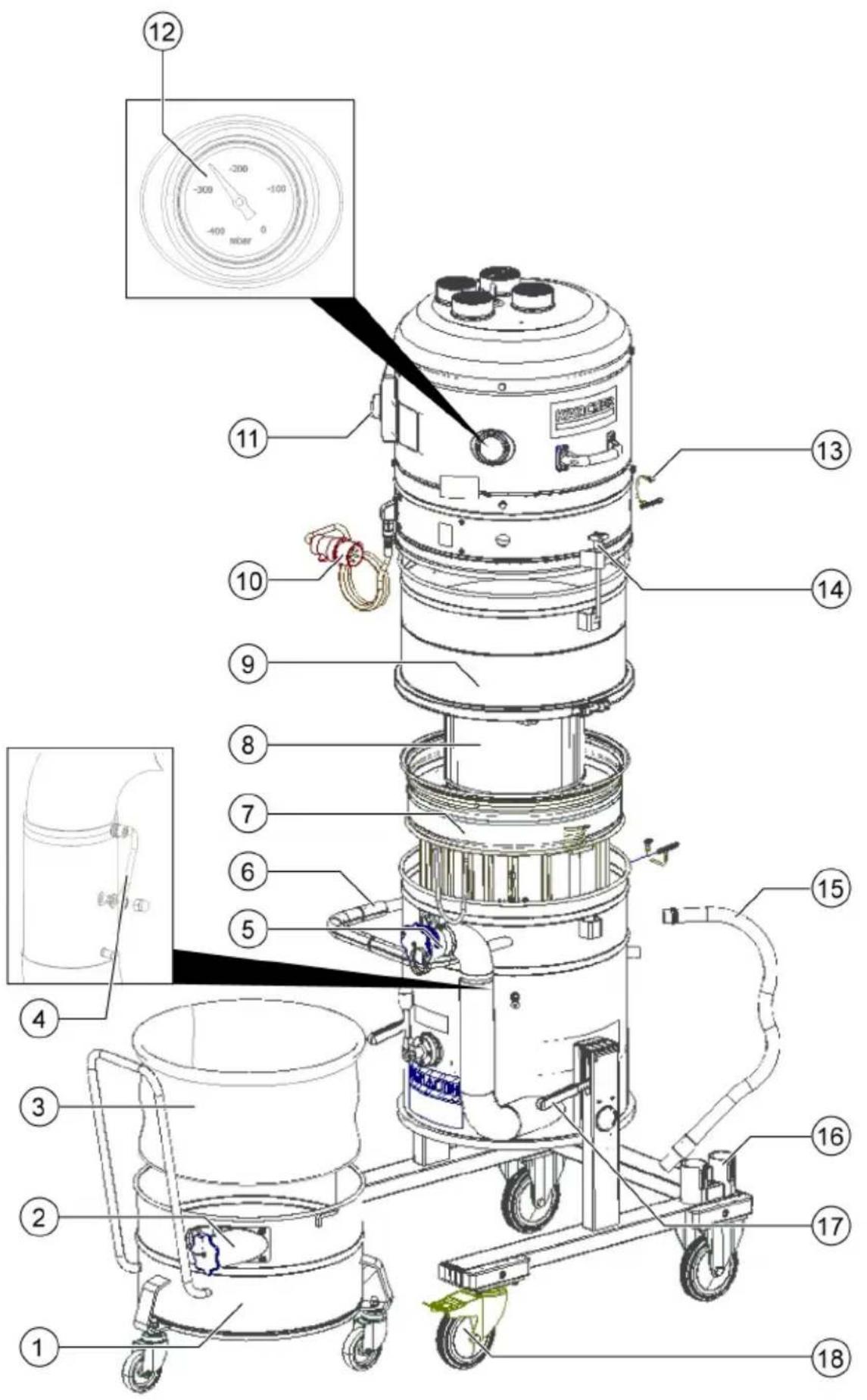
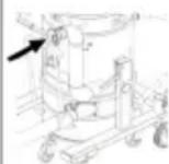
Illustration A
① Dirt receptacle
②Suction hose connection on the dirt receptacle
③ Dust bag
④ Equipotential bonding cable
⑤Suction hose connection on the filter ring
⑥Push handle
⑦ Main filter
⑧H filter
⑨ Spacer for H filter
⑩Power cable
⑪ Power switch
⑫Gauge
⑬Equipotential bonding cable
⑭Suction head lock
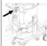
15 Pressure equalization tube
⑯Accessory holder
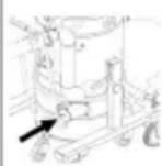
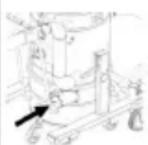
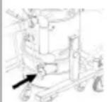
⑰ Lever for lowering the dirt receptacle
⑱Steering rollers with parking brake
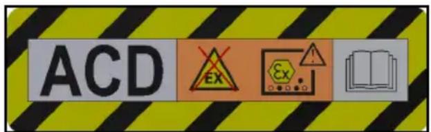
Symbols on the device
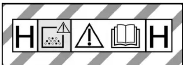
text_image
H HThe device is suitable for vacuuming dusts up to dust class H.
WARNING: This device contains dusts that are harmful to your health. Emptying and maintenance, including removal of the dust bag, may only be performed by appropriately trained personnel wearing suitable personal protective equipment. Do not switch on until the entire filter system has been installed and the volume flow control functionality has been checked.
⚠ WARNING
Damage to the skin, lungs and eyes
Expulsion of fine dust during emptying and maintenance work and disposal Wear the prescribed personal protective gear when performing during emptying and maintenance work, including disposal of the dust bag.
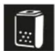
text_image
ACD EX ExThe device is suitable for vacuuming flammable dusts, installation outside zone 22.
WARNING: This device must not be placed in any zone 22. If a zone 22 is present, an EX-device must be used.
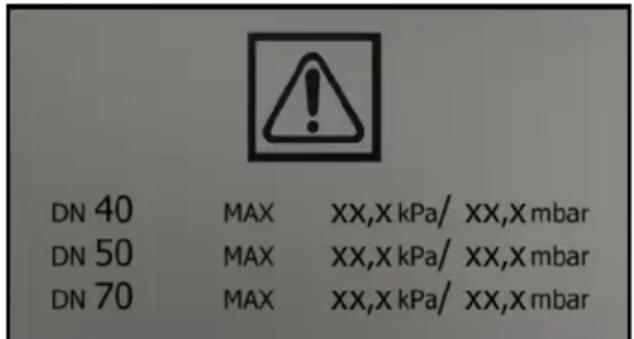
text_image
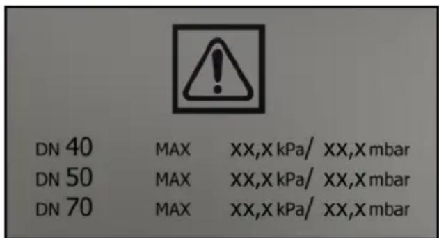
DN 40 MAX XX,X kPa/ XX,X mbar DN 50 MAX XX,X kPa/ XX,X mbar DN 70 MAX XX,X kPa/ XX,X mbarThe maximum vacuum value in relation to the hose cross-section is specified on the label. The actual value can be read on the pressure gauge. For the values applicable to this device, see chapter Reading the minimum volumetric flow. If this value is not reached, the main filter must be cleaned (see chapter Cleaning the main filter) or replaced (see chapter Replacing the main filter). The various different hose cross-sections allow adaptation to the various different connection cross-sections of the accessories.
IVR 60

Dust bag
(Order no. 9.989-606.0)

Safety filter bag
(Order no. 6.904-420.0)
Main filter
(Order no. 9.981-681.0)
H14 filter
(Order no. 9.980-249.0)
IVR 100

Dust bag
(Order no. 9.989-607.0)

Safety filter bag
(Order no. 6.904-420.0)
Main filter
(Order no. 9.981-681.0)
H14 filter
(Order no. 9.980-249.0)
Top-heavy device
Further instructions must be observed when transporting or moving the device.
Initial startup
⚠ WARNING
Potential equalisation line not connected correctly
Electric shock
Every time before use, check whether the equipotential bonding conductor (earthing conductors) are connected.
⚠ WARNING
Danger from dust that is harmful to your health
Respiratory sicknesses through inhalation of dust.
Do not vacuum without correctly installed filter elements, otherwise a danger to health from increased fine dust emission is present.
ATTENTION
Missing filter element
Damage to the suction motor
Do not vacuum without a filter element.
- Bring the device into the working position.
- Secure the device with the parking brakes.
- Ensure that the suction head is fitted correctly.
- Insert the suction hose (not included in the scope of delivery) into the suction connection.
- Check the filling level in the dirt receptacle (see chapter Check the dirt receptacle filling level).
- Empty the dirt receptacle if necessary (see chapter Emptying the dirt receptacle).
- Depending on the application, insert the dust bag or the safety filter bag before dry vacuuming (see chapter Fitting the dust bag/safety filter bag)
Illustration B
- Fit the desired accessory (not included in the scope of delivery) onto the suction hose.
Selecting the suction connection
The suction hose can be plugged into 2 different suction hose ports depending on the application.
• Suction hose port on the filter ring
– Dry vacuuming with dust bag: Coarse dust, large quantities of suction material for a short time
The dust bag is not included in the scope of delivery and can be ordered separately, order no. 9.989-606.0 (5 pieces).
– Wet vacuum cleaning
- Suction hose port on the dirt receptacle
– Dry vacuuming with a safety filter bag: Fine dust, continuously large amounts of suction material
The device is equipped with a dust bag with cable ties, order no. 6.904-420.0 (5 pieces).
– Wet vacuum cleaning
natural_image
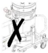
Technical line drawing of a mechanical device with a black X mark on the handle (no text or symbols present)Two suction hoses must not be connected to the vacuum cleaner at the same time. One of the suction hose ports must be tightly closed with the sealing plug.
When using the dust bag, the lower suction hose port must be tightly closed.

When using the safety filter bag, the upper suction hose port must be tightly closed.
Closing the suction connection
⚠ WARNING
Risk of injury
Damage to the skin, lungs and eyes through fine dust
The suction connection must be closed using the sealing plug after removing the suction hose.
- Remove the suction hose.
Illustration C
- Insert the sealing plug precisely into the suction connection.
- Push the sealing plug in all the way to the end stop.
- Turn the sealing plug to the right until the suction connection is tightly closed.
Check the dirt receptacle filling level
The dirt receptacle must be emptied when filled to the lower edge of the suction hose port on the dirt receptacle. The device does not switch off automatically if the maximum filling level is exceeded.
- Check the dirt receptacle filling level regularly.
Operation
The device is suitable for vacuuming fine dust up to dust class H.
⚠ WARNING
Danger from dust that is harmful to your health
Respiratory sicknesses through inhalation of dust.
Do not vacuum without correctly installed filter elements, otherwise a danger to health from increased fine dust emission is present.
ATTENTION
Risk of damage to the suction motor.
Never remove the main filter element when vacuuming.
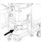
Fitting the dust bag/safety filter bag
- Secure the device with the parking brakes.
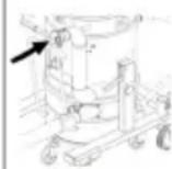
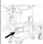
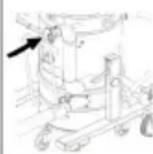
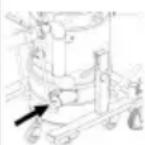
- Disconnect the pressure equalisation hose from the dirt receptacle.
Illustration D
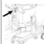
- Lower the dirt receptacle by pulling up the lever.
Illustration E
- Pull the dirt receptacle out of the device.
Fitting the dust bag
Illustration F
- Fit the dust bag in the dirt receptacle and carefully position it against the container wall and the container floor.
- Fold the edge of the dust bag over the edge of the dirt receptacle to the outside.
Fitting the safety filter bag Illustration G
- Fit the safety filter bag.
Illustration H
- Fold the edge of the safety filter bag out over the edge of the dirt receptacle.
Illustration E
- Fit the dirt receptacle in the device.
Illustration D
⚠ WARNING
Improper handling when locking the dirt receptacle
Risk of crushing
Under no circumstances should you hold your hands between the dirt receptacle and filter ring or allow them to come close to the lifting mechanism while locking it.
Lock the dirt receptacle by operating the le-vers with both hands.
- Lock the dirt receptacle with the levers.
- Fit the pressure equalisation hose on the dirt receptacle.
Removing the dust bag/ safety filter bag
⚠️DANGER
Danger from dust that is harmful to your health
Respiratory sicknesses through inhalation of dust.
Accumulated dust must be transported in dust-proof containers. Do not transfer the contents. The dust bag may only be disposed of by qualified staff.
- Secure the device with the parking brakes.
- Remove the suction hose if necessary.
- Close the suction connection on the dirt receptacle (see chapter Closing the suction connection).
- Disconnect the pressure equalisation hose from the dirt receptacle.
Illustration D
- Lower the dirt receptacle by pulling up the lever.
Illustration E
- Pull the dirt receptacle out of the device.
Removing the dust bag Illustration I
- Turn up the dust bag.
- Seal the dust bag tightly with the cable tie.
- Remove the dust bag.
- Dispose of the dust bag in accordance with statutory regulations.
Removing the safety filter bag Illustration J
- Fold up the safety filter bag.
Illustration K
- Peel off the protective film.
- Close the safety filter bag with the self-adhesive flap.
- Pull the safety filter bag out towards the rear.
Illustration L
- Seal the suction connection opening of the safety filter bag tightly with the cover.
Illustration M
-
Close the safety filter bag tightly with the attached cable tie.
-
Remove the safety filter bag from the dirt receptacle.
-
Clean the interior of the dirt receptacle with a moist cloth.
-
Dispose of the used safety filter bag in dust-tight bag in accordance with statutory regulations.
Illustration E
- Fit the dirt receptacle in the device.
Illustration D
⚠ WARNING
Improper handling when locking the dirt receptacle
Risk of crushing
Under no circumstances should you hold your hands between the dirt receptacle and filter ring or allow them to come close to the lifting mechanism while locking it.
Lock the dirt receptacle by operating the le-vers with both hands.
-
Lock the dirt receptacle with the levers.
-
Fit the pressure equalisation hose on the dirt receptacle
Switching on the device
-
Plug the mains plug into the socket.
-
Switch on the device at the trigger. Illustration N
-
Start vacuuming.
Reading the minimum volumetric flow
A gauge is mounted on the front of the device that shows the vacuum intensity (see chapter Device description).
The table shows the maximum vacuum intensity value. This value depends on the unit performance and the suction hose used.
ATTENTION
Suction loss
If the specified value is exceeded, the air speed in the suction hose drops below 20 m/s.
Clean the main filter when the value is reached, or sooner (see chapter Cleaning the main filter.
Replace the main filter if the value is not significantly reduced by cleaning (see chapter. Replacing the main filter).
| Power | Hose diameter Value |
| 3.0 kW | DN40 200 mbar (20 kPA) |
| 3.0 kW | DN50 150 mbar (15 kPA) |
| 4.0 kW | DN40 226 mbar (22.6 kPA) |
| 4.0 kW | DN50 216 mbar (21.6 kPA) |
- Clean the main filter before or when the specified value is reached.
Cleaning the main filter
Note
Clean the main filter regularly to avoid a loss of suction power.
Illustration O
- Move the main filter cleaning handle back and forth several times to clean the filter.
Switching off the device
-
Switch off the device at the On/Off switch.
-
Empty and clean the dirt receptacle.
-
Remove the accessory and clean and dry if necessary.
Each time after use
Emptying the dirt receptacle
The dirt receptacle must be emptied as necessary and after each use.
-
Switch off the device and disconnect from the mains supply.
-
Clean the main filter.
-
Remove the dirt receptacle from the device and replace the dust bag (see chapter Replacing the dust bag) or the safety filter bag (see chapter Replacing the safety filter bag).
Note
Only move the dirt receptacle on its rollers. Do not use a crane, forklift or similar means.
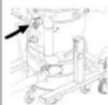
Removing the suction head
△CAUTION
Failure to observe the weight
Risk of injury and damage
Only lift the suction head. Because of its weight, do not remove the suction head by hand.
⚠️DANGER
Failure to observe the weight
Risk of injury from falling device
Observe the applicable accident prevention guidelines and safety instructions.
Every time before lifting, check to ensure correct functioning of the lifting device.
Only lift the device via the provided crane grommet.
Ensure that there will be no unintentional unhooking of the lifted load.
The crane may exclusively be operated by qualified staff.
No people may be located within the hazard zone of the crane.
Do not leave the device hanging unattended on the crane.
Illustration P
- Switch off the device and disconnect it from the mains supply.
- Open the suction head lock.
- Attach a suitable hoist to the crane grommet.
- Use the crane to lift the suction head and place it on a suitable surface.
Storing the device
- Wind the mains cable onto the cable holders.
- Store the device in a dry room and secure it against unauthorised use.
Transport
△CAUTION
Failure to observe the weight
Risk of injury and damage
Be aware of the weight of the device during transportation.
Illustration Q
△CAUTION
Top-heavy device
Risk of tipping over, risk of injury
When moving the IVR 100/30 Sc H ACD and IVR 100/40 Sc H ACD devices, make sure that the device does not tip over. Due to the height of the devices, we recommend removing the suction head (see chapter Removing the suction head).
The dirt receptacle is emptied.
- Close both suction connections for dust-free transport (see chapter Closing the suction connection).
- Release the parking brakes and push the device by the push handle.
- Grasp the device by the chassis and the push handle for loading.
- Secure the device against slipping and tipping over when transporting in vehicles.
Storage
⚠CAUTION
Failure to observe the weight
Risk of injury and damage
Only store the device on level surfaces to prevent it from tipping over.
Be aware of the weight of the device during storage.
The dirt receptacle is emptied.
- Store the device indoors only.
Care and maintenance
⚠️DANGER
Inadvertently starting up device, touching live components
Risk of injury, electric shock
Switch off the device before performing any work on the device.
Remove the mains plug.
⚠️DANGER
Danger from dust that is harmful to your health
Respiratory sicknesses through inhalation of dust.
Wear a breathing protection mask of class P2 or higher and disposable clothing when performing maintenance work (e.g. filter change).
⚠️DANGER
Inadequate filtration
Respiratory sicknesses through inhalation of dust.
The effectiveness of the filtration of the device can be tested by the test method specified in EN 60 335-2-69 22.AA.201.2. This test must be carried out at least annually or more frequently if specified in national requirements.
If the test result is negative, repeat the test with a new filter.
⚠ WARNING
Danger from dust that is harmful to your health
Respiratory sicknesses through inhalation of dust.
Safety devices providing hazard protection must be checked for correct safety-related functionality at least annually by the manufacturer or an appropriately instruction person, e.g. absence of leaks, filter damage, functionality of the monitoring devices.
ATTENTION
Care agents containing silicone
These can attach plastic components.
Do not use care agents containing silicone for cleaning.
Dust extraction machines are safety devices for the prevention or elimination of hazards according to the German BGV A1.
- For servicing performed by the user, the device must be disassembled, cleaned and maintained only to the degree that this is possible without presenting a danger to the maintenance personnel and other persons. Suitable precautionary measures include detoxification before disassembly. Make provisions for local forced ventilation at the location where the device is to be disassembled, for cleaning the maintenance surface and to ensure adequate protection for the personnel.
- The exterior of the device should be detoxified by vacuuming and wiped clean, or treated with sealant before being removed from the hazardous area. All unit parts must be regarded as contaminated
when they are taken from the hazardous area. Suitable measures must be taken to prevent distribution of the dust.
- All contaminated objects resulting from maintenance and repair work that cannot be satisfactorily cleaned must be correctly disposed of. Such objects must be disposed of in sealed bags in accordance with the applicable regulations for the disposal of this type of waste.
-
The suction hose ports are to be closed using the sealing plugs during transport and maintenance of the device.
-
Note that you can carry out simple maintenance and care work yourself.
-
Clean the surface of the device and the interior of the container regularly with a moist cloth.
Inspection and maintenance work
Have the device regularly inspected according to the respective national accident prevention regulations. Maintenance work as specified by the manufacturer must be performed by a technically qualified person at the specified regular intervals and in accordance with the applicable regulations and safety requirements. Work on electrical components may only be performed by a qualified electrician. Please contact a KÄRCHER branch office if you have any questions.
Replacing the main filter
⚠️DANGER
Danger from dust that is harmful to your health
Respiratory sicknesses through inhalation of dust.
Accumulated dust must be transported in dust-proof containers. Do not transfer the contents. The dust bag may only be disposed of by qualified staff.
⚠ WARNING
Danger from dust that is harmful to your health
Respiratory sicknesses through inhalation of dust.
Do not use the main filter element after removing it from the device.
Permanently installed filters may only be replaced in suitable areas, e.g. in so-called decontamination stations) by a technical expert.
Illustration R
①Clamping ring
② Main filter
③Nuts
④Cleaning fixture
- Secure the device with the parking brakes.
- Switch off the device at the power switches.
- Pull out the mains plug.
- Remove the suction head, see chapter Removing the suction head.
- Release the tensioning strap on the spacer of the H filter.
- Remove the spacer of the H-filter with the H-filter cartridge.
- Remove the filter unit from the device using the handles and turn it over. Illustration S
- Remove the nuts and remove the cleaning fixture.
- Loosen the clamping ring screw connection.
- Remove the main filter.
- Dispose of the foam filter.
- Insert the new main filter.
- Insert the new foam filter.
- Fit the tensioning ring and screw it in place.
- Fit the cleaning device and screw it on.
- Insert the filter inlay. In doing so, make sure the tab on the filter inlay fits into the shaft.
Illustration T
Replacing the H filter
- Secure the device with the parking brakes.
- Switch off the device at the power switches.
- Pull out the mains plug.
Illustration U
-
Remove the suction head, see chapter Removing the suction head.
-
Release the tensioning strap on the spacer of the H filter.
- Remove the spacer of the H-filter with the H-filter cartridge.
- Place the spacer upside down on a flat surface.
- Unscrew the nuts.
- Release and remove the H filter by turning it anti-clockwise.
- Immediately after removing the contaminated H filter from the device, place it in a bag and seal the bag tightly.
- Dispose of the contaminated H filter according to the legal requirements.
- Remove any dirt deposits from the clean air side.
- Fit the new H filter in the reverse order.
Replacing the dust bag
⚠️DANGER
Danger from dust that is harmful to your health
Respiratory sicknesses through inhalation of dust.
Accumulated dust must be transported in dust-proof containers. Do not transfer the contents. The dust bag may only be disposed of by qualified staff.
- Secure the device with the parking brakes.
- Remove the suction hose if necessary.
- Close the suction connection on the dirt receptacle (see chapter Closing the suction connection).
- Disconnect the pressure equalisation hose from the dirt receptacle.
Illustration D
- Lower the dirt receptacle by pulling up the lever.
Illustration E
- Pull the dirt receptacle out of the device.
Illustration I
- Turn up the dust bag.
- Seal the dust bag tightly with the cable tie.
- Remove the dust bag.
- Dispose of the dust bag in accordance with statutory regulations.
Illustration F
- Insert the new dust bag in the dirt receptacle and carefully place it against the container wall and the container floor.
- Fold the edge of the dust bag over the edge of the dirt receptacle to the outside.
Illustration E
- Fit the dirt receptacle in the device.
Illustration D
⚠ WARNING
Improper handling when locking the dirt receptacle
Risk of crushing
Under no circumstances should you hold your hands between the dirt receptacle and filter ring or allow them to come close to the lifting mechanism while locking it.
Lock the dirt receptacle by operating the le-vers with both hands.
-
Lock the dirt receptacle with the levers.
-
Fit the pressure equalisation hose on the dirt receptacle.
Replacing the safety filter bag
⚠️DANGER
Danger from dust that is harmful to your health
Respiratory sicknesses through inhalation of dust.
Accumulated dust must be transported in dust-proof containers. Do not transfer the contents. The dust bag may only be disposed of by qualified staff.
- Secure the device with the parking brakes.
- Remove the suction hose if necessary.
- Close the suction connection on the dirt receptacle (see chapter Closing the suction connection).
- Disconnect the pressure equalisation hose from the dirt receptacle.
Illustration D
- Lower the dirt receptacle by pulling up the lever.
Illustration E
- Pull the dirt receptacle out of the device.
Illustration J
- Fold up the safety filter bag.
Illustration K
-
Peel off the protective film.
-
Close the safety filter bag with the self-adhesive flap.
-
Pull the safety filter bag out towards the rear.
Illustration L
- Seal the suction connection opening of the safety filter bag tightly with the cover.
Illustration M
- Close the safety filter bag tightly with the attached cable tie.
- Remove the safety filter bag from the dirt receptacle.
- Clean the interior of the dirt receptacle with a moist cloth.
- Dispose of the used safety filter bag in dust-tight bag in accordance with statutory regulations.
Illustration G
- Fit the new safety filter bag.
Illustration H
- Fold the edge of the safety filter bag out over the edge of the dirt receptacle.
Illustration E
- Fit the dirt receptacle in the device.
Illustration D
⚠ WARNING
Improper handling when locking the dirt receptacle
Risk of crushing
Under no circumstances should you hold your hands between the dirt receptacle and filter ring or allow them to come close to the lifting mechanism while locking it.
Lock the dirt receptacle by operating the le-vers with both hands.
- Lock the dirt receptacle with the levers.
- Fit the pressure equalisation hose on the dirt receptacle.
Troubleshooting guide
⚠️DANGER
Risk of injury
Danger of the device unintentionally starting and danger of electric shock
Switch off the device and unplug the mains plug before performing any work on the device.
Have all checks and work on electrical parts performed by an qualified technician.
The motor (suction turbine) does not start up
No electrical voltage present
- Check the socket and the power supply fuse.
- Check the mains cable and the mains plug of the device.
The suction power decreases
Nozzle, suction hose or suction pipe clogged.
- Check the nozzle, the suction hose and the suction pipe and clean if necessary. The main filter is dirty.
- Clean the main filter.
Disposal
At the end of its service life, the device is to be disposed of in accordance with statutory regulations.
Warranty
The warranty conditions issued by our sales company responsible apply in all countries. We shall remedy possible malfunctions on your device within the warranty period free of cost, provided that a material or manufacturing defect is the cause. In a warranty case, please contact your dealer (with the purchase receipt) or the next authorised customer service site. (See overleaf for the address)
Technical data
| IVR 60/30 Sc H ACD | IVR 100/30 Sc H ACD | IVR 100/40 Sc H ACD | |||
| Electrical connection | |||||
| Mains voltage V 400 400 400 | |||||
| P | h | a | s | e | ~ |
| Power frequency Hz 50 50 50 | |||||
| Protection type IPX4 IPX4 IPX4 | |||||
| Protection class | I | I | I | ||
| Nominal power | W | 3000 | 3000 | 3000 | |
| Power protection (slow-blowing) | A 16 16 32 | ||||
| Dimensions and weights | |||||
| Typical operating weight | kg | 175 180 205 | |||
| Length x width x height | mm | 855 x 760 x 1959 | 855 x 760 x 2265 | 855 x 760 x 2380 | |
| Filter area of main filter | m^2 | 1,75 | 1,75 | 1,75 | |
| Filter area of the H filter | m^2 | 3,5 | 3,5 | 3,5 | |
| Ambient conditions | |||||
| Storage temperature | °C | -10-40 | -10-40 | -10-40 | |
| IVR 60/30 Sc H ACD | IVR 100/30 Sc H ACD | IVR 100/40 Sc H ACD | ||
| Device performance data | ||||
| Container capacity I 60 100 100 | ||||
| Air quantity I/s 87,5 87,5 137,5 | ||||
| Air flow volume during operation I/s 56,5 56,5 88,5 | ||||
| Vacuum kPa(mbar) | 26 (260) 26 (260) 14 (140) | |||
| Operating pressure kPa(mbar) | 21 (210) 21 (210) 11,5 (115) | |||
| Suction hose connection | NW DN70 | NW DN70 | NW DN70 | |
| Nominal width of the suction hose | DN40/50 | DN40/50 | DN40/50 | |
| Main filter order number | 9.981-681.0 | 9.981-681.0 | 9.981-681.0 | |
| Main filter order number | 9.980-249.0 | 9.980-249.0 | 9.980-249.0 | |
| Determined values in acc. with EN 60335-2-69 | ||||
| Hand-arm vibration value | m/s2 | <2,5 <2,5 | <2,5 | |
| K uncertainty | m/s2 | 0,2 | 0,2 | 0,2 |
| Sound pressure level LpA | dB(A) | 62 | 62 | 71 |
| Uncertainty KpA | dB(A) | 2 | 2 | 2 |
| Mains cable | ||||
| Mains cable H07BQ-F | mm2 | 4 x 2.5 | 4 x 2.5 | 4 x 2.5 |
| Part number (EU) | 9.979-856.0 | 9.979-856.0 | 9.981-557.0 | |
| Cable length | m | 7,5 | 7,5 | 7,5 |
| Subject to technical modifications. | EN 60335-2-69 | |||
| Declaration of Conformity | EN 55014-1: 2017 + A11: 2020 | |||
| EN 55014-2: 2015 | ||||
| EU Declaration of Conformity | EN IEC 61000-3-2: 2019 | |||
| We hereby declare that the machine described below complies with the relevant basic safety and health requirements in the EU Directives, both in its basic design and construction as well as in the version placed in circulation by us. This declaration is invalidated by any changes made to the machine that are not approved by us. Product: Dry vacuum cleanerProduct: Wet/dry vacuum cleanerType: 9.990-xxx | EN 61000-3-3: 2013 + A1: 2019 | |||
| EN 61000-3-11: 2000 | ||||
| EN 62233: 2008 | ||||
| EN IEC 63000: 2018 | ||||
| Non-harmonised standards used | ||||
| IEC 60335-1 | ||||
| IEC 60335-2-69 | ||||
| National standards used | ||||
| - | ||||
| The signatories act on behalf of and with the authority of the company management. | ||||
| Currently applicable EU Directives | ||||
| 2006/42/EC (+2009/127/EC) | ||||
| 2014/30/EU |  | |||
| 2011/65/EU | ||||
| Harmonised standards used | Managing partner | |||
| EN 60335-1 | M. Pfister | |||
Kärcher Industrial Vacuuming GmbH
73550 Waldstetten (Germany)
Ph.: +49 7171 94888-0
Fax: +49 7171 94888-528
Waldstetten, 23/10/01
Declaration of Conformity (UK)
We hereby declare that the product described below complies with the relevant provisions of the following UK Regulations, both in its basic design and construction as well as in the version put into circulation by us. This declaration shall cease to be valid if the product is modified without our prior approval.
Product: Dry vacuum cleaner
Product: Wet/dry vacuum cleaner
Type: 9.990-xxx
Currently applicable UK Regulations
S.I. 2008/1597 (as amended)
S.I. 2016/1091 (as amended)
S.I. 2012/3032 (as amended)
Designated standards used
EN 60335-1
EN 60335-2-69
EN 55014-1: 2017 + A11: 2020
EN 55014-2: 2015
EN IEC 61000-3-2: 2019
EN 61000-3-3: 2013 + A1: 2019
EN 61000-3-11: 2000
EN 62233: 2008
EN IEC 63000: 2018
Non-harmonised standards used
IEC 60335-1
IEC 60335-2-69
National standards used
The signatories act on behalf of and with the authority of the company management.

text_image
MPPickManaging partner
M. Pfister
Kärcher Industrial Vacuuming GmbH
73550 Waldstetten (Germany)
Ph.: +49 7171 94888-0
Fax: +49 7171 94888-528
Waldstetten, 23/10/01
Contenu
text_image
ACD EX Exnatural_image
Line drawing of a mechanical device with a black 'X' mark on the handle (no text or symbols present)
2006/42/CE (+2009/127/CE)
2014/30/UE
2011/65/UE
73550 Waldstetten (Germany)
Tél. : +49 7171 94888-0
natural_image
Line drawing of a mechanical device with a black X mark on the side (no text or symbols)

73550 Waldstetten (Germany)
Tel.: +49 7171 94888-0
Fax: +49 7171 94888-528
Waldstetten, 23/10/01
natural_image
Technical line drawing of a mechanical device with a black X mark on the handle (no text or symbols present)| IVR 60/30 Sc | IVR 100/30 | IVR 100/40 |
| H ACD | Sc H ACD | Sc H ACD |
2006/42/CE (+2009/127/CE)
2014/30/UE
2011/65/UE
natural_image
Simple line drawing of a mechanical device with a black 'X' mark on the handle (no text or symbols)
2006/42/CE (+2009/127/CE)
2014/30/UE
2011/65/UE
text_image
ACD Ex Ex O O Onatural_image
Line drawing of a mechanical device with a black 'X' mark on the left side (no text or symbols present)73550 Waldstetten (Germany)
Tel.: +49 7171 94888-0
Fax: +49 7171 94888-528
Waldstetten, 23/10/01
İçindekiler
Genel uyarılar 106
text_image
ACD EX Exnatural_image
Diagram of a mechanical device with a cross mark and wheels, no visible text or symbols


2006/42/AT (+2009/127/AT)
2014/30/AB
2011/65/AB
73550 Waldstetten (Germany)
Tel.: +49 7171 94888-0
Faks: +49 7171 94888-528
Waldstetten, 23/10/01
Innehåll
Allmän information 118
Säkerhetsinformation 119
text_image
ACD EX Ex 0 0 0 0 0 0 0 0 0 0 0 0 0 0 0natural_image
Technical line drawing of a mechanical device with a black X mark on the handle (no text or symbols present)
73550 Waldstetten (Germany)
Tfn: +49 7171 94888-0
Fax: +49 7171 94888528
Waldstetten, 23/10/01
Sisältö
natural_image
Line drawing of a mechanical device with a black 'X' mark on the handle (no text or symbols present)
73550 Waldstetten (Germany)
natural_image
Simple line drawing of a mechanical device with a black X mark on the handle (no text or symbols)Sette inn sikkerhetsfilterpose
Figur G
- Sett på sikkerhetsfilterposen.
Figur H
- Brett kanten av sikkerhetsfilterposen ut over kanten av smussbeholderen.
Figur E
- Sett smussbeholderen inn i apparatet.
Figur D
ADVARSEL
Feil fremgangsmåte ved låsing av smussbeholderen
Klemfare
2006/42/EF (+2009/127/EF)
2014/30/EU
2011/65/EU
Anvendte harmoniserte standarder
EN 60335-1
EN 60335-2-69
EN 55014-1: 2017 + A11: 2020
EN 55014-2: 2015
EN IEC 61000-3-2: 2019
EN 61000-3-3: 2013 + A1: 2019
EN 61000-3-11: 2000
EN 62233: 2008
EN IEC 63000: 2018
73550 Waldstetten (Germany)
Tlf.: +49 7171 94888-0
Faks: +49 7171 94888-528
Waldstetten, 23/10/01
Indhold
natural_image
Line drawing of a mechanical device with a black 'X' mark on the left side (no text or symbols present)2006/42/EF (+2009/127/EF)
2014/30/EU
2011/65/EU
73550 Waldstetten (Germany)
Tlf.: +49 7171 94888-0
Fax: +49 7171 94888-528
Waldstetten, 23/10/01
Sisukord
Üldjuhised 169
Ohutusjuhised 169
Sihtotstarbeline kasutamine.... 170
natural_image
Line drawing of a mechanical device with a black X mark on the handle (no text or symbols)

2006/42/EÜ (+2009/127/EÜ)
2014/30/EL
2011/65/EL
73550 Waldstetten (Germany)
Tel: +49 7171 94888-0
Faks: +49 7171 94888-528
Waldstetten, 23/10/01
Saturs
natural_image
Line drawing of a mechanical device with a black 'X' mark on the handle (no text or symbols)text_image
ACD EX Exnatural_image
Line drawing of a mechanical device with a black 'X' mark on the handle (no text or symbols present)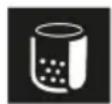

text_image
ACD EX Exnatural_image
Line drawing of a mechanical device with a black X mark on the handle (no text or symbols)text_image
ACD EX EX C:\Program Files\ADnatural_image
Technical line drawing of a mechanical device with a black X mark symbol (no text or labels)2006/42/ES (+2009/127/ES)
2014/30/EU
2011/65/EU
natural_image
Simple line drawing of a mechanical cart with a black 'X' mark on the side (no text or symbols)2006/42/ES (+2009/127/ES)
2014/30/EÚ
2011/65/EÚ
73550 Waldstetten (Germany)
Tel.: +49 7171 94888-0
Fax: +49 7171 94888-528
Waldstetten, 23/10/01
Kazalo
Splošni napotki.... 261
Varnostna navodila.... 262
Namenska uporaba.... 263
Zaščita okolja 263
Pribor in nadomestni deli.... 264
Obseg dobave.... 264
Opis naprave.... 264
Simboli na napravi.... 264
Zagon 265
Obratovanje.... 266
Prevažanje 269
Skladiščenje 269
text_image
ACD EX Ex Open Booknatural_image
Simple line drawing of a mechanical device with a black 'X' mark on the left side (no text or symbols)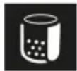

Na sesalnik ne smeta biti istočasno priključeni dve sesalni gibki cevi. Sesalna šoba mora biti tesno zaprta z zapiralnim čepom.
2006/42/ES (+2009/127/ES)
2014/30/EU
2011/65/EU
text_image
ACD EX Exnatural_image
Line drawing of a mechanical device with a black 'X' mark on the handle (no text or symbols present)
Directive UE relevante
2006/42/UE (+2009/127/UE)
2014/30/UE
2011/65/UE
Norme armonizate aplicate
EN 60335-1
EN 60335-2-69
EN 55014-1: 2017 + A11: 2020
EN 55014-2: 2015
EN IEC 61000-3-2: 2019
EN 61000-3-3: 2013 + A1: 2019
EN 61000-3-11: 2000
EN 62233: 2008
EN IEC 63000: 2018
Standarde nearmonizate aplicate
IEC 60335-1
IEC 60335-2-69
text_image
ACD EX ExUređaj je prikladan za usisavanje gorive prašine, postavljanje izvan zone 22.
UPOZORENJE: Ovaj se uređaj ne smije postavljati u zoni 22. Ako postoji zona 22, mora se upotrebljavati Ex uređaj.
text_image
DN 40 MAX XX,X kPa/ XX,X mbar DN 50 MAX XX,X kPa/ XX,X mbar DN 70 MAX XX,X kPa/ XX,X mbarnatural_image
Line drawing of a mechanical device with a black X mark on the handle (no text or symbols)
Na usisavaču ne smiju istovremeno biti priključena dva usisna crijeva. Usi- sni nastavak mora biti čvrsto zatvoren zapornim čepom.
Kod uporabe vrećice za zbrinjavanje donji usisni nastavak mora biti čvrsto zatvoren.
2006/42/EZ (+2009/127/EZ)
2014/30/EU
2011/65/EU
73550 Waldstetten (Germany)
Tel.: +49 7171 94888-0
Telefaks: +49 7171 94888-528
Waldstetten, 23/10/01
Sadržaj
Opšte napomene 302
Sigurnosne napomene.... 302
Namenska upotreba.... 303
Zaštita životne sredine.... 304
Pribor i rezervni delovi 304
Obim isporuke.... 304
natural_image
Technical line drawing of a mechanical device with a black X mark and no visible text or symbols
natural_image
Diagram showing a beaker and a mechanical device with an arrow pointing to it (no text or symbols present)Dva usisna creva ne smeju istovremeno biti povezana sa usisivačem. Usisni nastavak mora biti čvrsto zatvoren zaptivnim čepom. Prilikom upotrebe vrećice za odlaganje otpada, donji usisni nastavak mora da bude hermetički zatvoren.
Prilikom upotrebe sigurnosne filter kese, gornji usisni nastavak mora da bude hermetički zatvoren.
2006/42/EZ (+2009/127/EZ)
2014/30/EU
2011/65/EU
Primenjene harmonizovane norme
EN 60335-1
EN 60335-2-69
EN 55014-1: 2017 + A11: 2020
EN 55014-2: 2015
EN IEC 61000-3-2: 2019
EN 61000-3-3: 2013 + A1: 2019
EN 61000-3-11: 2000
EN 62233: 2008
EN IEC 63000: 2018
Primenjeni neharmonizovani standardi
IEC 60335-1
IEC 60335-2-69
Primenjene nacionalne norme
Potpisnici deluju u ime i sa punomoćju uprave kompanije.

text_image
MPPicksVodeći saradnik
M. Pfister
Kärcher Industrijsko usisavanje GmbH
natural_image
Simple line drawing of a mechanical device with a black 'X' mark on the side (no text or symbols)natural_image
Illustration of a beaker and a vehicle with an arrow pointing to it (no text or symbols present)natural_image
Diagram showing a device with a control panel and a schematic of a mechanical assembly (no text or symbols)73550 Waldstetten (Germany)
Tηλ.: +49 7171 94888-0
Φαξ: +49 7171 94888-528
Waldstetten, 23/10/01
Содержание
Общие указания 331
text_image
ACD EX Ex Open Booknatural_image
Simple line drawing of a mechanical device with a black 'X' mark on the side (no text or symbols)


natural_image
Technical line drawing of a mechanical device with a black X mark on the side (no text or symbols present)Не можна
одночасно
підключати до
пилососа два
всмоктувальні
шланги. Один з
всмоктувальних
патрубків має бути
text_image
ACD EX Exnatural_image
Diagram of a mechanical device with a black 'X' mark and a circular component, no readable text or symbols present.Към
73550 Waldstetten (Germany)
natural_image
Icon showing a gear and wrench inside a square frame (no text or symbols)http://www.kaercher.com/dealersearch