
WIND STYLANCE - Fan Create - Free user manual and instructions
Find the device manual for free WIND STYLANCE Create in PDF.

| Product type | Ceiling fan |
| Brand | Create |
| Model | WIND STYLANCE |
| Use | Indoor |
| Minimum mounting height | 2.3 m from floor |
| Minimum distance from wall/obstacle | 50 cm |
| Fan speeds | 3 speeds (adjustable via remote control) |
| Rotation direction | Clockwise (winter) and counterclockwise (summer) |
| Reverse function | Yes |
| Integrated light | Optional (model with or without light) |
| Color temperature (light) | Warm, neutral, cool (model with light) |
| Remote control | Yes, with AAA batteries (2×) |
| Timer | Yes (auto shut-off: 1H, 4H, etc.) |
| Wi-Fi connectivity | Yes (compatible model) |
| Mobile app | CREATE (Android and iOS) |
| Power supply | 220-240 V ~ 50 Hz |
| Safety | Installation by qualified electrician; do not use with dimmer; minimum height 2.3 m |
| Maintenance | Clean with a soft, dry cloth; do not use abrasive products |
| Package contents | Fan, remote control, installation kit, balancing kit, manual |
Frequently Asked Questions - WIND STYLANCE Create
User questions about WIND STYLANCE Create
0 question about this device. Answer the ones you know or ask your own.
Ask a new question about this device
Download the instructions for your Fan in PDF format for free! Find your manual WIND STYLANCE - Create and take your electronic device back in hand. On this page are published all the documents necessary for the use of your device. WIND STYLANCE by Create.
USER MANUAL WIND STYLANCE Create
Location and installation requirements 6
Mechanic tips 6
Electrical Tips 6
Security instructions 7
Parts list 8
Before assembly 8
Remote control 9
Installation instructions 10
Installation preparation 10
Installing the mounting bracket 10
Downrod installation 10
Assembling and hanging the fan 11
Wiring connection 12
Remote control connection 12
Canopy assembly 12
Blades assembly 13
Connections panel assembly 13
Decorative cover assembly 14
Light assembly 14
Check the installation 14
Connection to the app 15
How to connect to the app 15
PORTUGUÊS
Thank you for choosing our ceiling fan. Before using this appliance and to ensure its best use, please read the instructions carefully.
The safety measures listed here reduce the risk of fire, electric shock, and injury when followed correctly. Please keep the manual in a safe place for future reference, as well as the sales receipt and box. If applicable, give these instructions to the future owner of the appliance.
Always follow basic safety instructions and hazard prevention measures when using an electrical appliance. The manufacturer will not be responsible for any damage resulting from the user's failure to follow these instructions.
LOCATION AND INSTALLATION REQUIREMENTS
MECHANIC TIPS
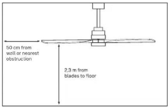
- According to safety regulations, the lowest point of the fan blade must be at least 2.3m (7 feet) from the floor.
- Please make sure the chosen location will not allow the rotating fan blades to come into contact with any objects.
- Ensure ceiling joists are sound and are large and strong enough to support the weight of the fan.
- To reduce the risk of fire, electric shock or personal injury, ensure that the fan mounting bracket is attached directly to the building structure. Do not mount to an outlet box.
- The mounting bracket must be firmly screwed to a load bearing structure, e.g. a concrete ceiling, steel structure or timber frame. If a timber frame is added, it must be securely nailed or screwed between two beams.
- To reduce risk of personal injury and property damage, do not bend or damage the downrod or the fan blades when handling or installing them. If you notice any product imperfections, please contact our after-sales service before proceeding to install the fan.
- Make sure the ceiling fan is securely fastened to the ceiling. All set screws must be checked and re-tightened where necessary before fan operation.
ELECTRICAL TIPS
- Turn off the power before performing any work on the ceiling fan and turn off the power breaker. To avoid possible electrical shock, check that the power is turned off at the fuse box or circuit breaker panel before wiring.
- The fan, mounting bracket and lighting equipment must be connected to a ground. Check that all splices are well insulated.
- Check and confirm that all connections are correct and secure. Once all electrical connections have been made, store all cables securely.
- Do not attempt to control this fan from a wall switch or remote control that is not approved by the manufacturer for use with the fan. Do not use a solid state controller. Use of a non-approved wall switch or remote control will void your warranty.
- Do not connect the ceiling fan to a dimmer switch.
When using any electrical appliance, the following basic safety precautions should always be observed.
- To reduce the risk of personal injury, attach the fan directly to the building support structure following these instructions and use only the material provided.
- To avoid possible electrical shock, before installing your fan, disconnect power by turning off the electrical panel power switches and associated wall switches. If it is not possible to turn off the power switches, use a warning device such as a label on the electrical panel.
- All cables must meet specifications established by local and national electrical codes and ANSI/NFPA 70. If you are not familiar with electrical installations, consult a qualified electrician.
- Do not bend the blade attachment system while installing, tilting, or cleaning blades.
- Do not insert other objects between the fan blades.
- To reduce the risk of fire, electric shock, or motor damage, do not use a solid-state speed regulator with this fan. Only use the original speed regulators.
- This appliance can be used by children aged 8 years and older and people with reduced physical, sensory or mental capabilities, or lack of experience or limited knowledge, provided they are supervised by a person responsible for their safety or who has been trained how to use it. the appliance safely.
- Children should not play with this device. They should also not carry out cleaning and maintenance tasks unless they are over 8 years old and supervised. Children should be closely supervised when using any appliance.
NOTE: The instructions and safety precautions in this manual may not cover all possible problems and situations. You should understand that both common sense and caution are essential in the installation and use of the fan.
PARTS LIST
Carefully open the packaging and remove all the items included. Place them on a carpet or a big piece of plastic to avoid any damage.
Check that all the items listed below have been included.
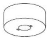
Canopy
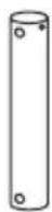
Bar Extension bar
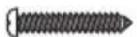
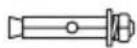
Extension screws
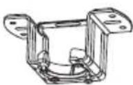
Mounting bracket
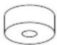
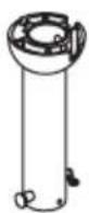
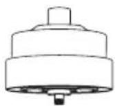
Trim Motor
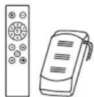
Command & controller
X3 Blades Connections panel
Option with light: Option without light:
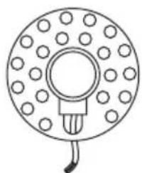
natural_image
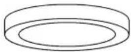
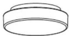
Simple line drawing of a circular component with evenly spaced dots and a central bulb, no text or symbols present.LED panelDecorative shade Decorative cover

Fixing screws
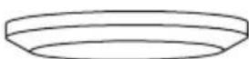
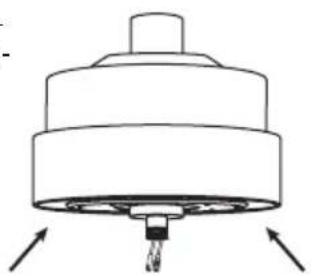
BEFORE ASSEMBLY
- Remember to remove the three plastic protective tabs from the bottom of the motor before starting assembly.
natural_image
Technical line drawing of a mechanical component with arrows indicating direction (no text or symbols)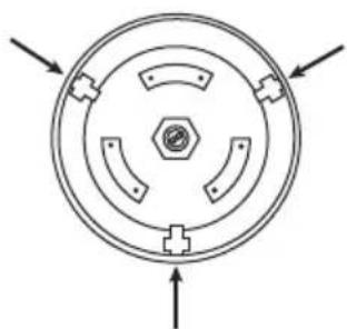
natural_image
Circular mechanical component diagram with three symmetrical slots and directional arrows (no text or symbols)- **Light
- ON/OFF button
- Timer
- **Color temperature control
- Fan intensity control
- Reverse function
- Sound off button
- Batteries (2 x AAA)
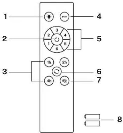
** Function only available for the WITH LIGHT option.

LIGHT
Turns the fan light on and off regardless of whether the fan is running or not.

COLOUR TEMPERATURE
Toggles between the three types of available light colour temperatures (warm, neutral, and cool).

ON/OFF
Turns the fan on or off completely, regardless of whether it has the light on or off.

FAN INTENSITY
Increase or decrease the rotation speed of the fan blades.

TIMER
Schedule automatic shutdown by choosing from the available options.

REVERSE FUNCTION
Change the direction of rotation of the fan blades. The winter function (turn to the right) forces the hot air accumulated in the ceiling downwards and the summer function (turn to the left) generates a breeze that cools the environment.

DISABLE SOUND
By pressing the sound off button you can silence the sounds that the fan makes when you press any key on the remote control.
- Mark the correct position of the holes and fix the ceiling bracket using the screws with metal anchor or screws and washers suitable for the type of ceiling chosen.
- Check the correct installation of the bracket before hanging the fan. This plate must support the full weight of the fan.
INSTALLATION PREPARATION
• To prevent personal injury and damage, ensure that the hanging location allows the blades a clearance of 2.3 m from the floor and 50 cm from any wall or obstruction.
- Be sure the outlet box is securely attached to the building structure and can support the full weight of the fan.
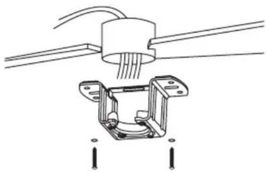
INSTALLING THE MOUNTING BRACKET
- Check that the ceiling where you intend to mount the fan is stable and capable of safely supporting the weight of the fan.
- Do not fix the mounting bracket directly on ceilings less than 10mm to avoid the risk of the screw loosening and coming out.
natural_image
Technical line drawing of a mechanical assembly with no visible text or symbolsWood roof
Drill the necessary holes and then secure the mounting bracket with the wood screws and washers to the ceiling joints.
natural_image
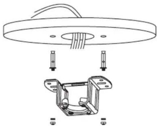
Technical line drawing of a mechanical assembly with a circular component and bracket (no text or symbols)Concrete roof
Drill holes with an 8mm drill bit, according to the length of the expansion screws. Next, secure the mounting bracket to the ceiling with the expansion screws.
NOTE: This fan can also be installed in a false ceiling, for this you must use fixing screws with a spring lever (not included).
- Mark the correct position of the holes and fix the ceiling support using the screws with metal anchors or screws and washers suitable for the type of ceiling chosen.
- Verify proper installation of the bracket before hanging the fan. The mounting bracket must support the entire weight of the fan.
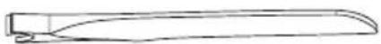
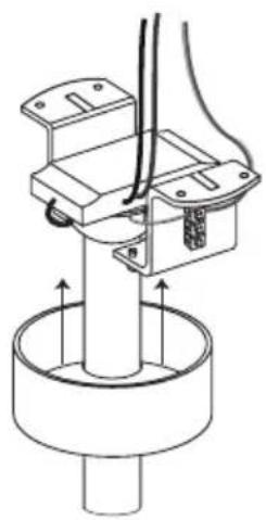
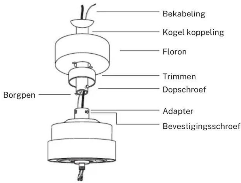
DOWNROD INSTALLATION
- Choose the suspension bar that best suits your situation: it has a 15 cm and a 25 cm suspension bar.
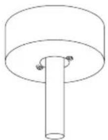
- Remove the bar bolt, removing the pin, and pass the canopy (roof trim) and the engine canopy through the suspension bar. Next, route the fan motor cables through the inside of the suspension bar. Tighten the suspension bar to the engine and insert the bolt and pin.
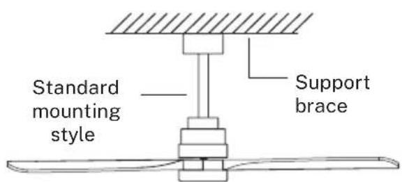
Standard Mounting hangs from the ceiling by a downrod.
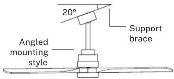
Angled Mounting recommended for a vaulted or angled ceiling.
ASSEMBLING AND HANGING THE FAN
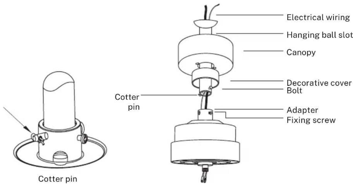
- If you wish to extend the hanging length of your fan, you must remove the hanging ball from the 6 inch downrod provided to use with an extended downrod (included). (If you wish to use the 6 inch downrod, please proceed to instructions below.)
- To remove the hanging ball, loose the set screw on the hanging ball and remove the pin and bolt. Lower hanging ball and remove stop pin. Slide hanging ball off the original downrod, and slide it down the longer downrod (the top of the downrod should be noted as having a fixing screw hole; use this hole when setting the fixing screw).
- Insert stop pin into top of extended downrod and raise hanging ball.
- Be sure that the stop pin aligns with the slots on the inside of the hanging ball, tighten the fixing screw securely.
Tip: To prepare for threading electrical wires through the downrod, apply a small piece of electrical tape to the ends of the electrical wires. This will keep the wires together when threading them through the downrod.
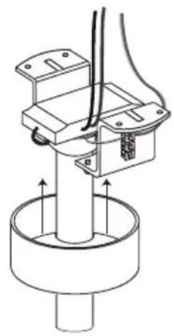
- Loosen the fixing screws and nut at the top of the motor housing. Remove the pin and bolt from the downrod (if you have not already done so). Slide the downrod through the canopy.
- Tread electrical wires through the downrod and pull extra wire slack from the upper end of the downrod.
- Place the downrod into the motor housing yoke and reinsert the pin and bolt that were previously removed. Tighten the fixing screws and nut securely.
- Lower the canopy to the motor housing.
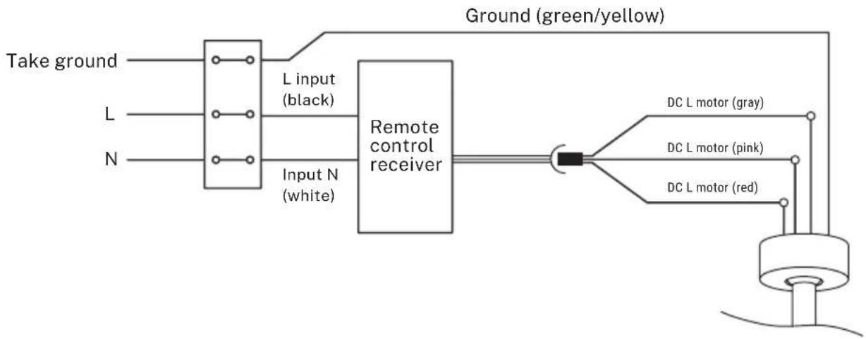
WIRING CONNECTION
Make the connection between the receiver wires and the fan motor wires following the color indications. Make sure the connection is tight.
flowchart
graph LR
    A["Take ground"] --> B["L input (black)"]
    C["L"] --> D["Remote control receiver"]
    E["N"] --> D
    B --> D
    D --> F["DC L motor (gray)"]
    D --> G["DC L motor (pink)"]
    D --> H["DC L motor (red)"]
    I["Ground (green/yellow)"] --> D
REMOTE CONTROL CONNECTION
- Make the connection between the receiver cables and the fan motor cables following the color indications. Make sure the connection is tight.
natural_image
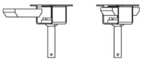
Technical line drawing of two mechanical assembly components (no text or symbols)CANOPY ASSEMBLY
natural_image
Technical line drawing of a mechanical assembly with no visible text or symbols123
natural_image
Mechanical assembly diagram showing a rotating shaft and housing component (no text or labels)O
natural_image
Simple line drawing of a cylindrical object with a central rod and two small circular features at the top (no text or symbols)O
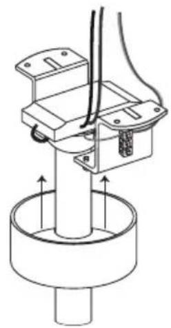
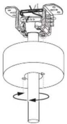
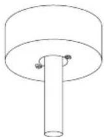
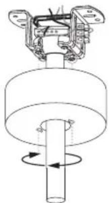
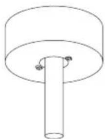
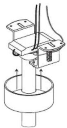
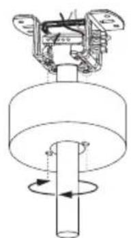
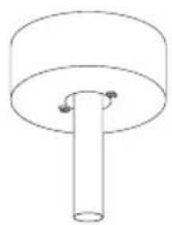
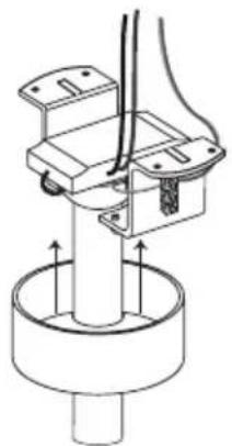
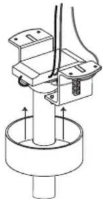
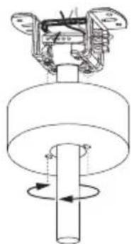
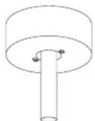
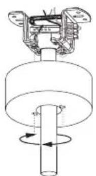
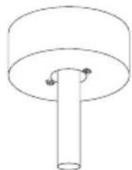
- Raise the canopy to hanging bracket, aligning loosened screws in hanging bracket with slotted holes in the canopy.
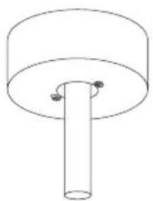
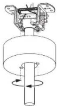
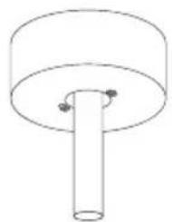
- Twist the canopy to lock. Re-insert the screws and secure all the screws with a screwdriver.
- With hanging bracket secured to the outlet box and able to support the fan, you are now ready to hang your fan.
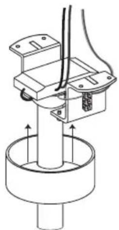
- Grab the fan firmly with two hands. Slide downrod through the opening in the hanging bracket and let the hanging ball rest on the hanging bracket.
- Turn the hanging ball slot until it lines up with the hanging bracket tab.
Tip: Seek the help of another person to hold the stepladder in place and to lift the fan up to you once you are set on the ladder.
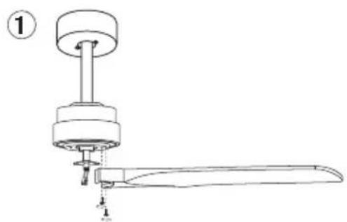
BLADES ASSEMBLY
Align the holes on the blade holder with the holes on the blades and the motor body and screw them in place, but don't tighten them until they are all placed and screwed in.
Tip: To save time, you can fit the washers on each screw prior to installing the blades.
natural_image
Technical line drawing of a mechanical device with a handle and base, labeled with number 1 (no text or symbols on the diagram itself)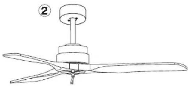
natural_image
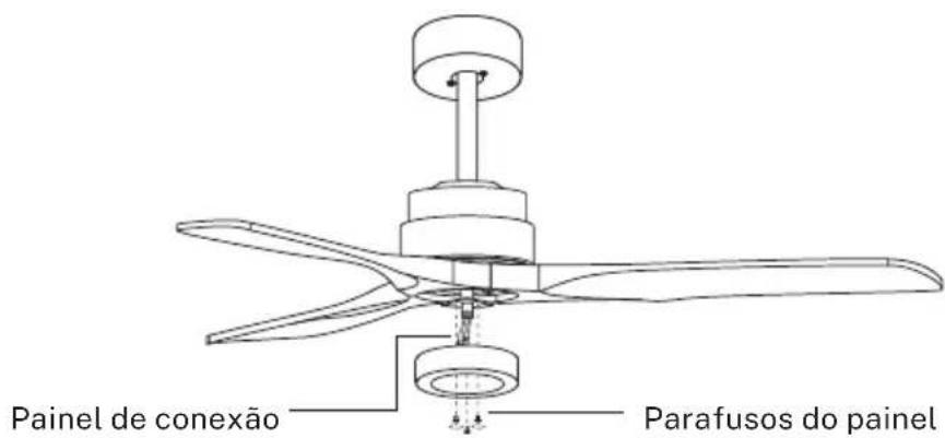
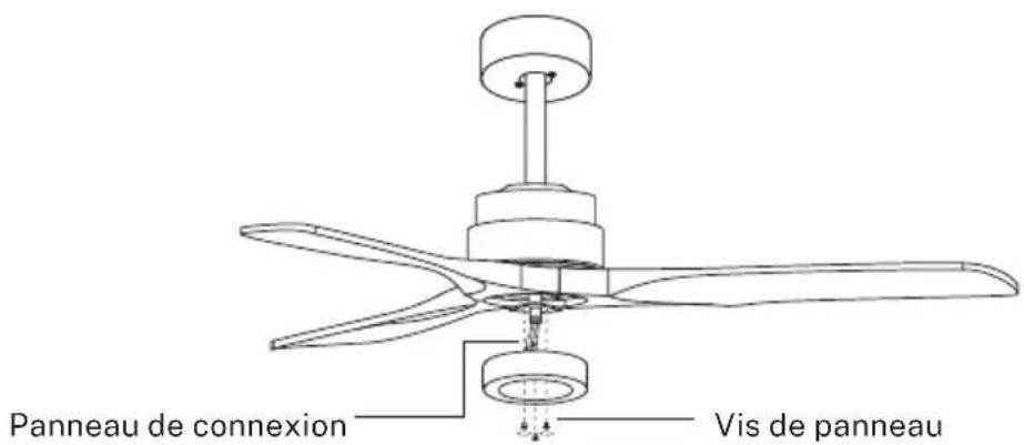
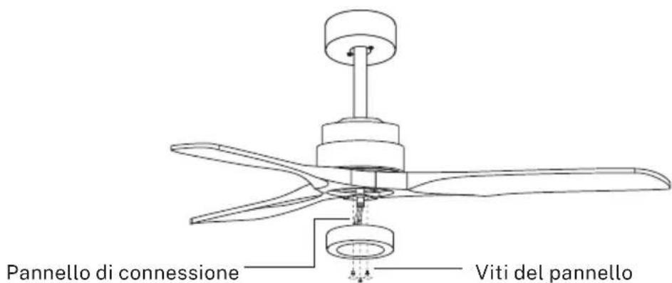
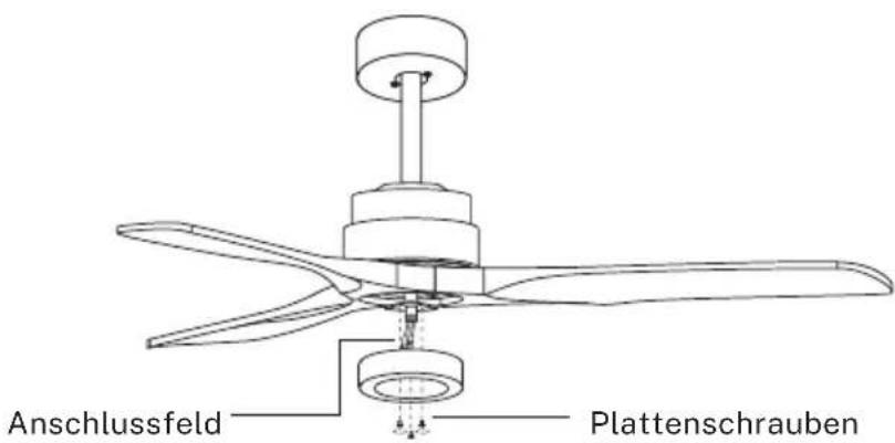
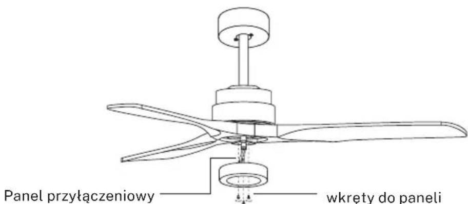
Line drawing of a three-blade propeller with a top hub and labeled component (no text or symbols)CONNECTIONS PANEL ASSEMBLY
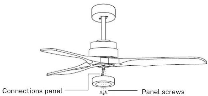
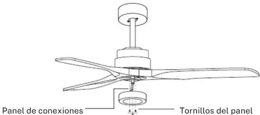
Attach the connections plate up to the bottom of the fan by inserting the set screw heads into the key hole slots. Rotate them to place and tighten them to secure the plate.
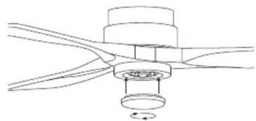
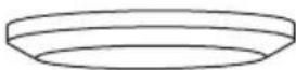
DECORATIVE COVER ASSEMBLY
* Only for the model WITHOUT LIGHT
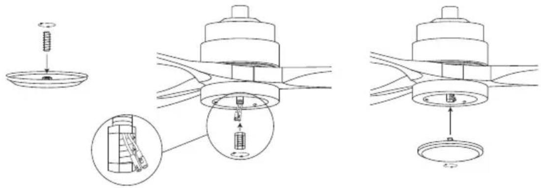
Once the connections plate has been assembled and secured, screw the decorative cover back to the connections plate using the central screw.
LIGHT ASSEMBLY
* Only for the model WITH LIGHT
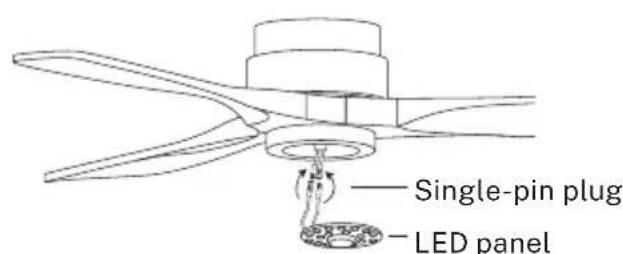
natural_image
Pure mechanical diagram showing a rotating component with curved lines and a central circular feature (no text or symbols)Connect the single-pin plugs of the connections plate with the ones on the LED panel. The LED panel is magnetized so it will be attached to the connections panel just by placing them together.
Note: While installing or removing the LED plate, please keep the insulation pads intact carefully. Turning the set screws over-tightly or fast will damage the insulation pads.
Screw the lamp shade back to the connections plate.
CHECK THE INSTALLATION
- Check the correct operation of the ceiling fan, checking that no strange movement or misalignment is observed in any part of the fan.
- In the event that some kind of hum / vibration can be seen, you can proceed to adjust the blades with the shooting kit.
- This kit has self-adhesive weights and "u" shaped clips.
• Turn off the ceiling fan. - You can put the clip in the center of any blade and check if the vibration decreases.
- Turn on the fan and check. If no change is seen, turn off the fan and add another clip to a different blade or use the adhesive weights.
* Only for models with Wi-Fi
The CREATE app is available for both Android and iOS (search for the app on Google Play or App Store or scan the QR code below). There may be additional costs depending on the provider.
This device is used through your home network. As an essential requirement, you must have a Wi-Fi network always connected to your 2.4 Gh router and the free CREATE application. (Internet providers currently offer both 5Gh and 2.4Gh simultaneously.)
We recommend that you disconnect the appliance from the mains when you are away from home to prevent it from accidentally starting up while you are away.


iPhone Android
HOW TO CONNECT TO THE APP
- Install the CREATE app and create a user account.
- Set a login password and log in to the app.
- Click "Add Device" (+) and then click the category for the ceiling fan.
- On the remote control, press and hold the 1H and 4H buttons for about 5 seconds until you hear a beep.
- Next, click "Confirm".
- Enter your Wi-Fi network password and confirm.
- While connecting, make sure your router, mobile phone and device are as close as possible. Finally, the ceiling fan will be successfully added to your CREATE application.
In compliance with Directives: 2012/19/EU and 2015/863/EU on the restriction of the use of dangerous substances in electric and electronic equipment as well as their waste disposal. The symbol with the crossed dustbin shown on the package indicates that the product at the end of its service life shall be collected as separate waste. Therefore, any products that have reached the end of their useful life must be given to waste disposal centres specialising in separate collection of waste electrical and electronic equipment, or given back to the retailer at the time of purchasing new similar equipment, on a one for one basis. The adequate separate collection for the subsequent start-up of the equipment sent to be recycled, treated and disposed of in an environmentally compatible way contributes to preventing possible negative effects on the environment and health and optimises the recycling and reuse of components making up the apparatus. Abusive disposal of the product by the user involves application of the administrative sanctions according to the laws.
natural_image
Circular diagram with a central bulb and internal dots, no text or symbols presentPanel LEDPantalla decorativa Cubierta decorativa
natural_image
Technical line drawing of a mechanical component with arrows indicating direction (no text or symbols)
natural_image
Circular mechanical component diagram with three symmetrical slots and a central hexagonal nut, no text or symbols presentnatural_image
Technical line drawing of a mechanical assembly with wires and mounting brackets (no text or symbols)Techo de madera
natural_image
Technical diagram of a mechanical assembly with a circular component and a bracket (no text or symbols)Techo de hormigón
natural_image
Technical line drawing of two mechanical assembly components (no text or symbols)MONTAJE DEL FLORÓN
natural_image
Technical line drawing of a mechanical assembly with no visible text or symbols123

natural_image
Mechanical assembly diagram showing a rotating shaft and housing component (no text or labels)O
natural_image
Simple line drawing of a cylindrical object with a central shaft and circular top (no text or symbols)O
natural_image
Technical line drawing of a mechanical device with a top component and lever (no text or symbols)
natural_image
Line drawing of a three-blade propeller with a top knob and labeled component (no text or symbols)MONTAJE DEL PANEL DE CONEXIONES
iPhone Android

CÓMO CONECTARSE A LA APP
natural_image
Circular diagram with a central bulb and internal dots, no text or symbols presentPainel de LEDTela decorativa Capa decorativa
natural_image
Technical line drawing of a mechanical component with arrows indicating direction (no text or symbols)
natural_image
Circular mechanical component diagram with three symmetrical slots and a central hexagonal nut, no text or symbols presentnatural_image
Technical line drawing of a mechanical assembly with wires and mounting brackets (no text or symbols)Telhado de madeira
natural_image
Technical line drawing of a ceiling lamp and its internal bracket assembly (no text or symbols)Telhado de concreto
natural_image
Technical line drawing of two mechanical assembly components (no text or symbols)MONTANDO A ROSA DO TETO
natural_image
Technical line drawing of a mechanical assembly with no visible text or symbols123
natural_image
Mechanical assembly diagram showing a rotating shaft and housing components (no text or labels)O
natural_image
Simple line drawing of a cylindrical object with a central rod and two small protrusions (no text or symbols)O
natural_image
Technical line drawing of a mechanical device with a handle and lever (no text or symbols)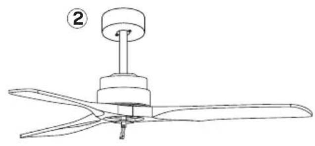
natural_image
Line drawing of a three-blade air conditioner fan with a top-mounted head and labeled component (no text or symbols)MONTAGEM EM PAINEL DE REMENDO
natural_image
Pure technical diagram of a mechanical component with no text, numbers, or symbols
Iphone Android
natural_image
Circular diagram with a central hole and internal dots, connected by wires (no text or symbols)natural_image
Technical line drawing of a mechanical component with arrows indicating force or movement (no text or symbols)
natural_image
Circular mechanical component diagram with three symmetrical slots and a central hexagonal nut, no text or symbols presentTÉLÉCOMMANDE
natural_image
Technical line drawing of a mechanical assembly with no visible text or symbolsToiture en bois
natural_image
Technical line drawing of a ceiling lamp and its internal bracket assembly (no text or symbols)Toit en béton
natural_image
Technical line drawing of two mechanical assembly components (no text or symbols)MONTAGE DE LA ROSACE
natural_image
Technical line drawing of a mechanical assembly with no visible text or symbols123

natural_image
Mechanical assembly diagram showing a rotating shaft and housing component (no text or labels)O
natural_image
Simple line drawing of a cylindrical object with a base and two small protrusions (no text or symbols)O
natural_image
Technical line drawing of a mechanical device with a lever and base (no text or symbols)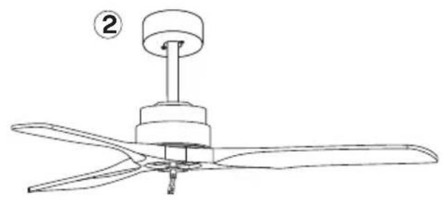
natural_image
Line drawing of a three-blade propeller with a top knob, labeled with number 2 (no text or symbols on the diagram itself)MONTAGE SUR PANNEAU DE BRASSAGE

iPhone Android
COMMENT SE CONNECTER À L'APPLICATION
natural_image
Circular diagram with a central hole and internal dots, connected by wires (no text or symbols)Pannello LEDSchermo decorativo Copertura decorativa

Viti di fissaggio
PRIMA DEL MONTAGGIO
natural_image
Technical line drawing of a mechanical component with arrows indicating direction (no text or symbols)
natural_image
Circular mechanical component diagram with three symmetrical slots and directional arrows (no text or symbols)natural_image
Technical line drawing of a mechanical assembly with wires and mounting brackets (no text or symbols)Tetto in legno
natural_image
Technical line drawing of a mechanical assembly with a circular component and bracket (no text or symbols)Tetto in cemento
natural_image
Technical line drawing of two mechanical assembly components (no text or symbols)MONTAGGIO DEL ROSONE
natural_image
Technical line drawing of a mechanical assembly with no visible text or symbols123
natural_image
Mechanical assembly diagram showing a rotating shaft and housing component (no text or labels)O
natural_image
Simple line drawing of a cylindrical object with a curved arrow indicating rotation or movement (no text or symbols)O
natural_image
Technical line drawing of a mechanical device with a lever and handle (no text or symbols)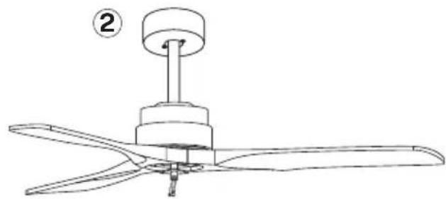
natural_image
Line drawing of a three-blade propeller with a top hub and labeled component (no text or symbols)MONTAGGIO SU PANNELLO PATCH
natural_image
Pure mechanical diagram showing a rotating component with curved lines and a central circular feature (no text or symbols)i phone Androide

COME CONNETTERSI ALL'APP
natural_image
Circular diagram with a central bulb and internal dots, no text or symbols presentnatural_image
Technical line drawing of a mechanical component with arrows indicating direction (no text or symbols)
natural_image
Circular mechanical component diagram with three symmetrical slots and a central hexagonal nut, no text or symbols presentFERNBEDIENUNG
natural_image
Technical line drawing of a mechanical assembly with wires and mounting brackets (no text or symbols)Holzdach
natural_image
Technical line drawing of a ceiling lamp and its internal bracket assembly (no text or symbols)Betondach
natural_image
Technical line drawing of two mechanical assembly components (no text or symbols)MONTAGE DES DECKENBALDACHINS
natural_image
Technical line drawing of a mechanical assembly with no visible text or symbols123
natural_image
Mechanical assembly diagram showing a rotating shaft and housing components (no text or labels)O
natural_image
Simple line drawing of a cylindrical object with a central shaft and two small protrusions (no text or symbols)O
natural_image
Line drawing of a mechanical device with a top component and lever mechanism (no text or symbols)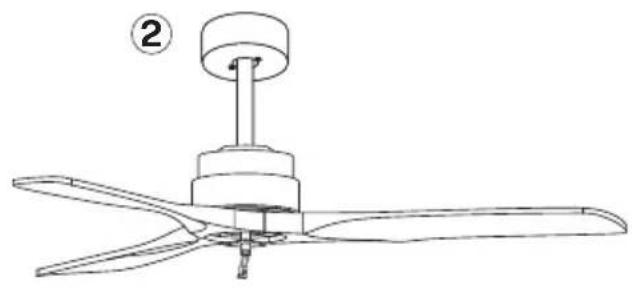
natural_image
Line drawing of a three-blade propeller with a top-mounted knob, labeled with number 2 (no text or symbols on the diagram itself)PATCH PANEL-MONTAGE
iPhone Android

natural_image
Circular diagram with a central bulb and internal dots, no text or symbols presentnatural_image
Technical line drawing of a mechanical component with arrows indicating direction (no text or symbols)
natural_image
Circular mechanical component diagram with three symmetrical slots and a central hexagonal nut, no text or symbols presentnatural_image
Technical line drawing of a mechanical assembly with wires and mounting brackets (no text or symbols)Houten dak
natural_image
Technical line drawing of a mechanical assembly with a circular component and bracket (no text or symbols)betonnen dak
natural_image
Technical line drawing of a mechanical device with a base and mounting bracket (no text or symbols)Borgpen
natural_image
Technical line drawing of a mechanical assembly with no visible text or symbols
PLAFONDKAPJE MONTEREN
natural_image
Technical line drawing of a mechanical assembly with no visible text or symbols123
natural_image
Mechanical assembly diagram showing a rotating shaft and housing components (no text or labels)O
natural_image
Simple line drawing of a cylindrical object with a curved arrow indicating rotation or movement (no text or symbols)O
natural_image
Technical line drawing of a mechanical device with a handle and base, labeled with number 1 (no text or symbols on the diagram itself)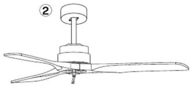
natural_image
Line drawing of a three-blade airship with a top-mounted knob, labeled with number 2 (no text or symbols on the diagram itself)PATCHPANEELMONTAGE

iPhone Android

HOE U VERBINDING MAAKT MET DE APP
natural_image
Circular diagram with a central bulb and internal dots, no text or symbols present
Śruby mocujące
natural_image
Technical line drawing of a mechanical component with arrows indicating direction (no text or symbols)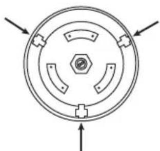
natural_image
Circular mechanical component diagram with three symmetrical slots and a central hexagonal nut, no text or symbols presentPILOT
INTENSYWNOŚĆ WENTYLATORA
natural_image
Technical line drawing of a mechanical assembly with wires and mounting brackets (no text or symbols)Dach drewniany
natural_image
Technical line drawing of a mechanical assembly with a circular component and bracket (no text or symbols)betonowy dach
natural_image
Technical line drawing of two mechanical assembly components (no text or symbols)MONTAŻ PODESTU SUFITOWEGO

natural_image
Technical line drawing of a mechanical assembly with no visible text or symbols1
natural_image
Mechanical assembly diagram showing a rotating shaft and housing components (no text or labels)2
natural_image
Simple line drawing of a cylindrical object with a central shaft and a curved arrow indicating rotation (no text or symbols)③
natural_image
Technical line drawing of a mechanical device with a handle and lever (no text or symbols)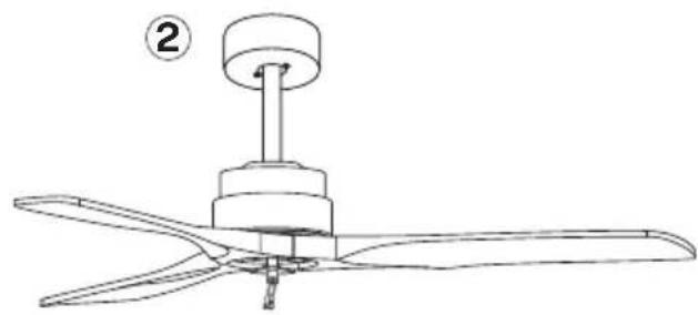
natural_image
Line drawing of a three-blade propeller with a top-mounted knob, labeled with number 2 (no text or symbols on the diagram itself)MONTAŻ PANELUKROSOWEGO
natural_image
Pure mechanical diagram showing a rotating component with curved lines and a central circular feature (no text or symbols)iPhone'a Android

JAK POŁĄCZYĆ SIE Z APLIKACJA

- PORTUGUÊS
- LOCATION AND INSTALLATION REQUIREMENTS
- MECHANIC TIPS
- ELECTRICAL TIPS
- PARTS LIST
- BEFORE ASSEMBLY
- LIGHT
- COLOUR TEMPERATURE
- ON/OFF
- FAN INTENSITY
- TIMER
- REVERSE FUNCTION
- DISABLE SOUND
- INSTALLATION PREPARATION
- INSTALLING THE MOUNTING BRACKET
- DOWNROD INSTALLATION
- ASSEMBLING AND HANGING THE FAN
- WIRING CONNECTION
- REMOTE CONTROL CONNECTION
- BLADES ASSEMBLY
- CONNECTIONS PANEL ASSEMBLY
- DECORATIVE COVER ASSEMBLY
- LIGHT ASSEMBLY
- CHECK THE INSTALLATION
- HOW TO CONNECT TO THE APP
- MONTAJE DEL FLORÓN
- MONTAJE DEL PANEL DE CONEXIONES
- CÓMO CONECTARSE A LA APP
- MONTANDO A ROSA DO TETO
- MONTAGEM EM PAINEL DE REMENDO
- TÉLÉCOMMANDE
- MONTAGE DE LA ROSACE
- MONTAGE SUR PANNEAU DE BRASSAGE
- COMMENT SE CONNECTER À L'APPLICATION
- PRIMA DEL MONTAGGIO
- Tetto in legno
- Tetto in cemento
- MONTAGGIO SU PANNELLO PATCH
- COME CONNETTERSI ALL'APP
- FERNBEDIENUNG
- MONTAGE DES DECKENBALDACHINS
- PATCH PANEL-MONTAGE
- PLAFONDKAPJE MONTEREN
- PATCHPANEELMONTAGE
- HOE U VERBINDING MAAKT MET DE APP
- PILOT
- INTENSYWNOŚĆ WENTYLATORA
- Dach drewniany
- betonowy dach
- MONTAŻ PODESTU SUFITOWEGO
- MONTAŻ PANELUKROSOWEGO
- JAK POŁĄCZYĆ SIE Z APLIKACJA
Brand : Create
Model : WIND STYLANCE
Category : Fan