ERA PRF0194191 - Basket ELICA - Free user manual and instructions
Find the device manual for free ERA PRF0194191 ELICA in PDF.

| Brand | Elica |
| Model | ERA PRF0194191 |
| Product type | Extractor hood or recirculation hood (indoor recirculation or external exhaust) |
| Use | Domestic and similar (community kitchens, offices, farms, hotels) |
| Minimum installation distance | 50 cm (electric hob) or 65 cm (gas/mixed hob) |
| Power supply | Conform to the voltage indicated on the rating plate (230V / 50Hz typical) |
| Maximum lighting power | LED 3W-E14 (max) |
| Number of lamps | Not specified (replace with identical lamps) |
| Filter material | Metallic grease filter, optional activated charcoal filter |
| Filter maintenance | Grease filter: monthly cleaning (hand or dishwasher, short low-temperature cycle); charcoal filter: replace every 4 months maximum, not washable |
| External cleaning | Damp cloth with neutral liquid detergent; no alcohol or abrasive tools |
| Safety | Unplug before maintenance; wear gloves; do not flambé cook; do not use without filter/lamp; adequate ventilation if used together with combustion appliances |
| Disposal | Do not dispose with household waste; follow WEEE directives (Directive 2012/19/EC) |
| Compliance standards | Safety: EN/IEC 60335-1, EN/IEC 60335-2-31, EN/IEC 62233; Performance: EN/IEC 61591, ISO 5167, EN/IEC 60704; EMC: EN 55014, CISPR 14, EN/IEC 61000 |
| Optional accessories | Smoke backdraft damper (depending on model) |
| Recommended use | Use the minimum speed during cooking; only accelerate in case of heavy steam; leave it running for a few minutes after cooking |
Frequently Asked Questions - ERA PRF0194191 ELICA
User questions about ERA PRF0194191 ELICA
0 question about this device. Answer the ones you know or ask your own.
Ask a new question about this device
Download the instructions for your Basket in PDF format for free! Find your manual ERA PRF0194191 - ELICA and take your electronic device back in hand. On this page are published all the documents necessary for the use of your device. ERA PRF0194191 by ELICA.
USER MANUAL ERA PRF0194191 ELICA
EN Instruction on mounting and use
natural_image
Diagram of a building interior with a central vertical structure and directional arrows indicating movement or flow (no text or symbols)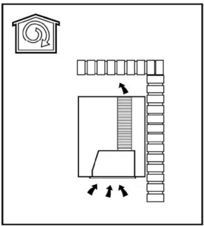
flowchart
graph TD
    A["House with circular refresh"] --> B["Flow from top to bottom"]
    B --> C["Shawn with horizontal bar and arrow indicating direction"]
    C --> D["Shawn with vertical bars and arrows indicating movement or flow direction"]
1
natural_image
Technical line drawing of a mechanical assembly with a cart and a component, no text or symbols present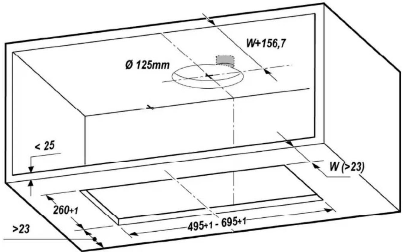
3
OK!
4
natural_image
3D diagram of a rectangular enclosure with internal compartments and a central display (no text or symbols)OK!
natural_image
Technical line drawing of a mechanical assembly inside a transparent enclosure, showing internal components and alignment lines (no text or symbols)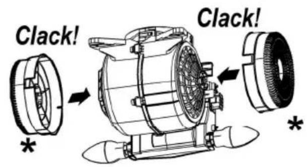
natural_image
Technical line drawing of a mechanical device with no visible text or symbols6
natural_image
Technical line drawing of a device interior showing internal components and a magnified view (no text or symbols)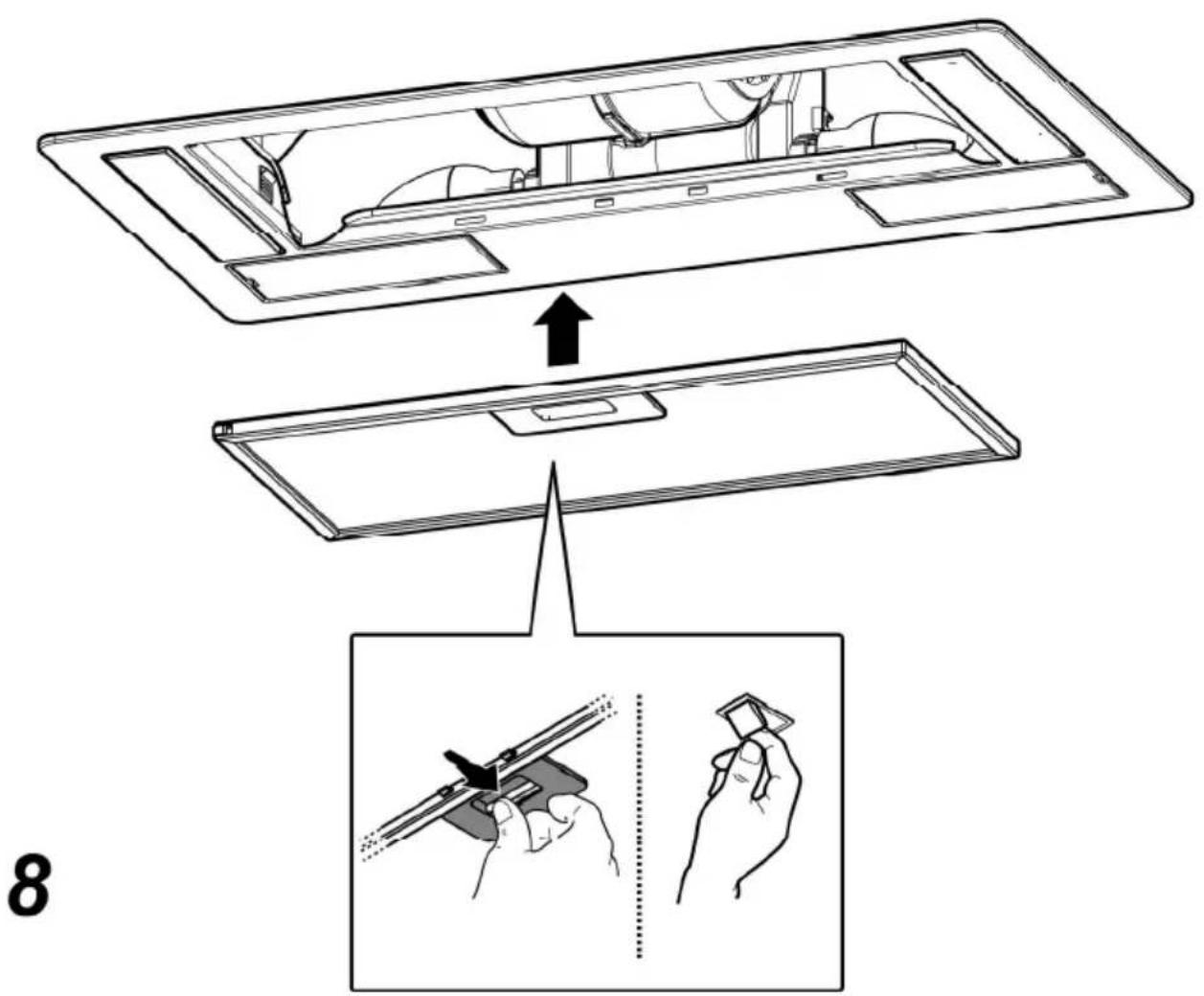

Closely follow the instructions set out in this manual. All responsibility, for any eventual inconveniences, damages or fires caused by not complying with the instructions in this manual, is declined. This appliance is intended to be used in household and similar application such as: - staff kitchen areas in shop, offices and other working environments; - farm houses; - by clients in hotels, motels and other residential type environments; - bed and breakfast type environments.
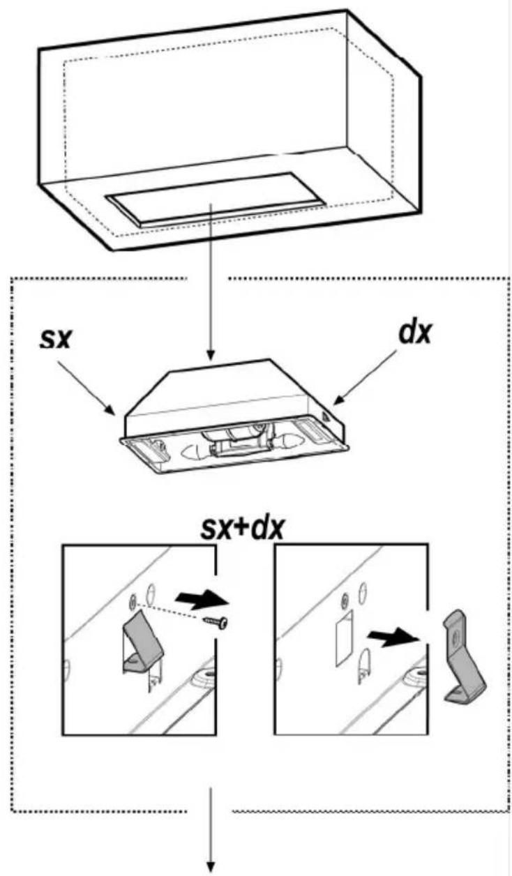
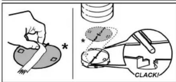
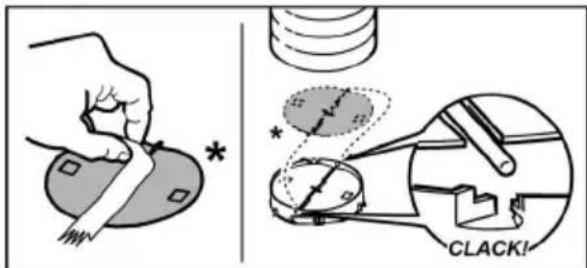
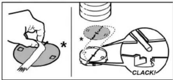
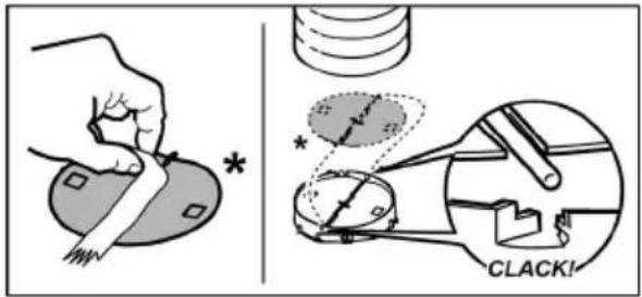
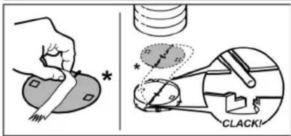
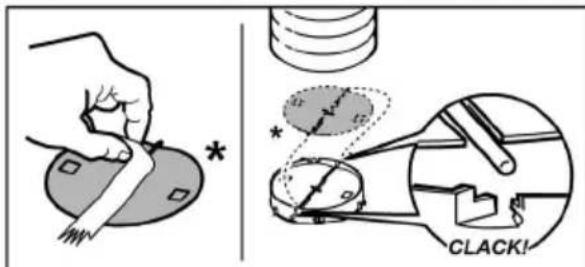
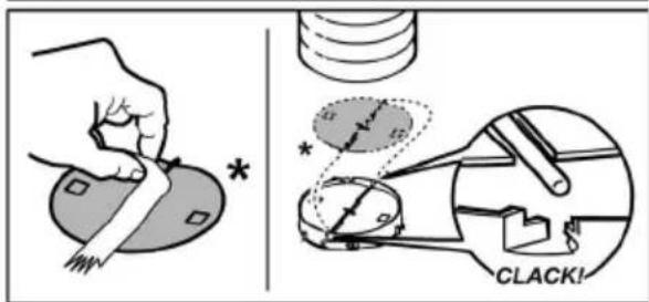
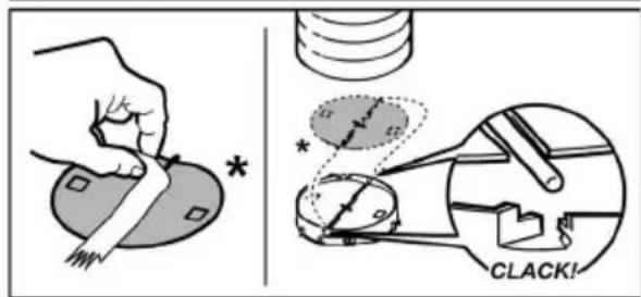
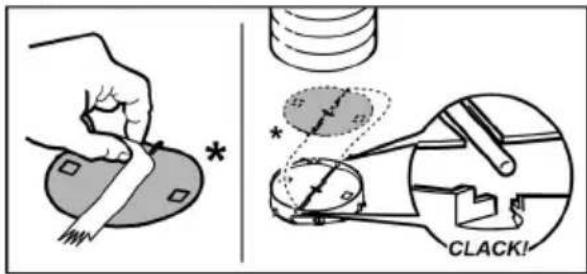
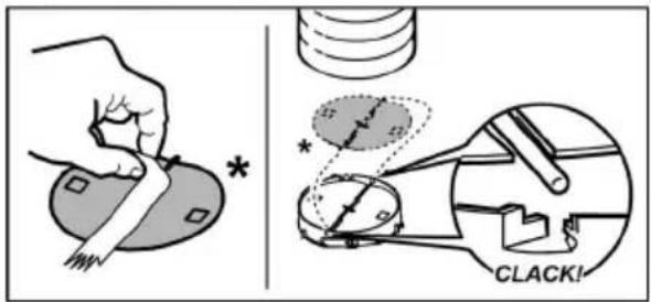
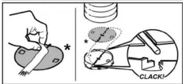
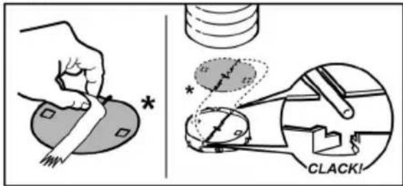
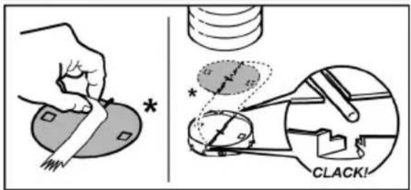
Note: The parts marked with the symbol "(*)" are optional accessories supplied only with some models or otherwise not supplied, but available for purchase.

Caution
- Before any cleaning or maintenance operation, disconnect hood from the mains by removing the plug or disconnecting the mains electrical supply.
• Always wear work gloves for all installation and maintenance operations. - This appliance can be used by children aged from 8 years and above and persons with reduced physical, sensory or mental capabilities or lack of experience and knowledge if they have been given supervision or instruction concerning use of the appliance in a safe way and understand the hazards involved.
- Children shall not be allowed to tamper with the controls or play with the appliance.
- Cleaning and user maintenance shall not be made by children without supervision.
- The premises where the appliance is installed must be sufficiently ventilated, when the kitchen hood is used together with other gas combustion devices or other fuels.
- The hood must be regularly cleaned on both the inside and outside (AT LEAST ONCE A MONTH).
- This must be completed in accordance with the maintenance instructions provided. Failure to follow the instructions provided regarding the cleaning of the
hood and filters will lead to the risk of fires.
- Do not flambé under the range hood.
- For lamp replacement use only lamp type indicated in the Maintenance/Replacing lamps section of this manual.
The use of exposed flames is detrimental to the filters and may cause a fire risk, and must therefore be avoided in all circumstances.
Any frying must be done with care in order to make sure that the oil does not overheat and ignite.
CAUTION: Accessible parts of the hood may become hot when used with cooking appliances.
- Do not connect the appliance to the mains until the installation is fully complete.
- With regards to the technical and safety measures to be adopted for fume discharging it is important to closely follow the regulations provided by the local authorities.
- The air must not be discharged into a flue that is used for exhausting fumes from appliance burning gas or other fuels.
- Do not use or leave the hood without the lamp correctly mounted due to the possible risk of electric shocks.
- Never use the hood without effectively mounted grids.
- The hood must NEVER be used as a support surface unless specifically indicated.
- Use only the fixing screws supplied with the product for installation or, if not supplied, purchase the correct screws type.
- Use the correct length for the screws which are identified in the Installation Guide.
- In case of doubt, consult an authorized service assistance center or similar qualified person.

WARNING!
- Failure to install the screws or fixing device in accordance with these instructions may result in electrical hazards.
- Do not use with a programmer, timer, separate remote control system or any other device that switches on automatically.
- This appliance is marked according to the European directive 2012/19/EC on Waste Electrical and Electronic Equipment (WEEE).
- By ensuring this product is disposed of correctly, you will help prevent potential negative consequences for the
environment and human health, which could otherwise be caused by inappropriate waste handling of this product.
- The symbol ■ on the product, or on the documents accompanying the product, indicates that this appliance may not be treated as household waste. Instead it should be taken to the appropriate collection point for the recycling of electrical and electronic equipment. Disposal must be carried out in accordance with local environmental regulations for waste disposal.
- For further detailed information regarding the process, collection and recycling of this product, please contact the appropriate department of your local authorities or the local department for household waste or the shop where you purchased this product.
Appliance designed, tested and manufactured according to:
- Safety: EN/IEC 60335-1; EN/IEC 60335-2-31, EN/IEC 62233.
• Performance: EN/IEC 61591; ISO 5167-1; ISO 5167-3; ISO 5168; EN/IEC 60704-1; EN/IEC 60704-2-13; EN/IEC 60704-3; ISO 3741; EN 50564; IEC 62301.
- EMC: EN 55014-1; CISPR 14-1; EN 55014-2; CISPR 14-2; EN/IEC 61000-3-2; EN/IEC 61000-3-3. Suggestions for a correct use in order to reduce the environmental impact: Switch ON the hood at minimum speed when you start cooking and kept it running for few minutes after cooking is finished. Increase the speed only in case of large amount of smoke and vapor and use boost speed(s) only in extreme situations. Replace the charcoal filter(s) when necessary to maintain a good odor reduction efficiency. Clean the grease filter(s) when necessary to maintain a good grease filter efficiency. Use the maximum diameter of the ducting system indicated in this manual to optimize efficiency and minimize noise.
Use
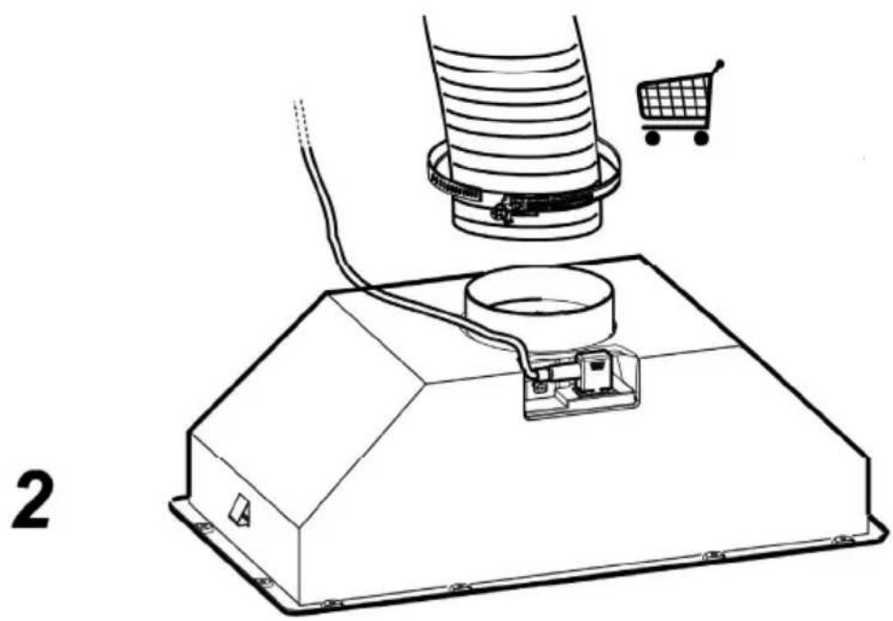
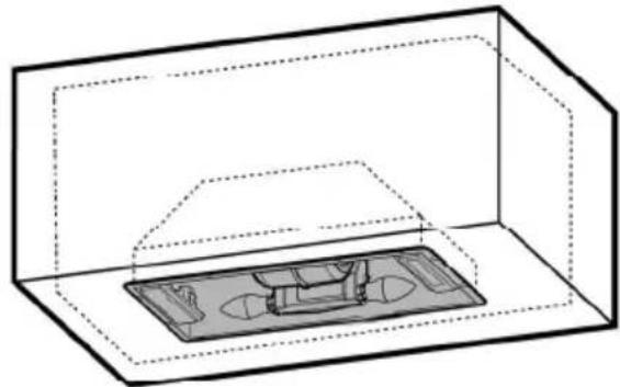
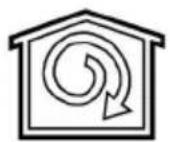
The hood is designed to be used either for exhausting

or filter version

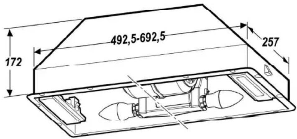
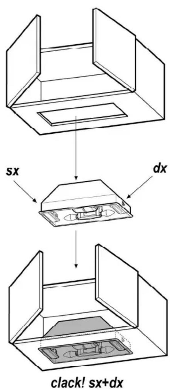
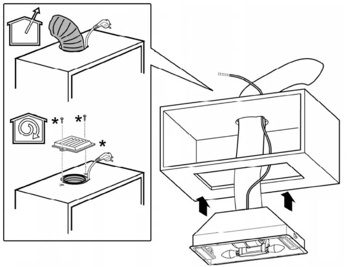
Installation
The minimum distance between the supporting surface for the cooking equipment on the hob and the lowest part of the range hood must be not less than 50cm from electric cookers and 65cm from gas or mixed cookers.
If the instructions for installation for the gas hob specify a greater distance, this must be adhered to.
The mains power supply must correspond to the rating indicated on the plate situated inside the hood. If provided with a plug connect the hood to a socket in compliance with current regulations and positioned in an accessible area, after installation. If it not fitted with a plug (direct mains connection) or if the plug is not located in an accessible area, after installation, apply a double pole switch in accordance with standards which assures the complete disconnection of the mains under conditions relating to over-current category III, in accordance with installation instructions.
WARNING!
Before re-connecting the hood circuit to the mains supply and checking the efficient function, always check that the mains cable is correctly assembled.
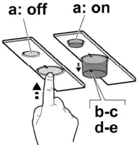
Operation
The hood is fitted with a control panel with aspiration speed selection control and a light switch to control cooking area lights.
Clean using ONLY a cloth dampened with neutral liquid detergent. DO NOT CLEAN WITH TOOLS OR INSTRUMENTS. Do not use abrasive products. DO NOT USE ALCOHOL!
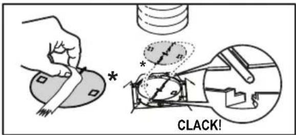
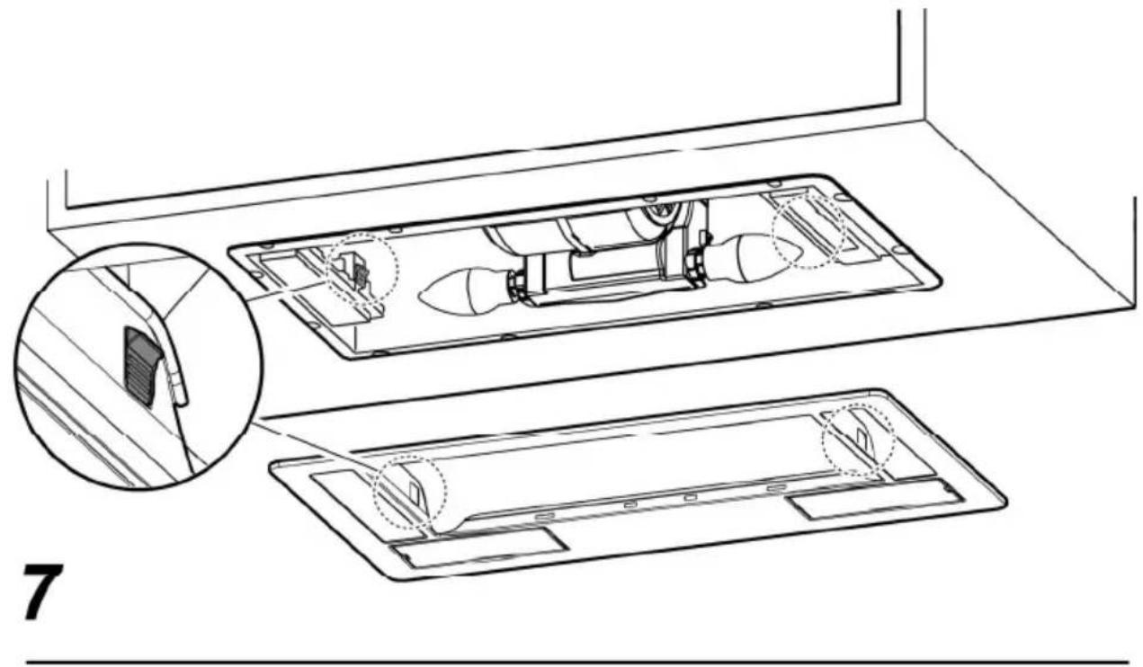
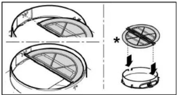
Grease filter
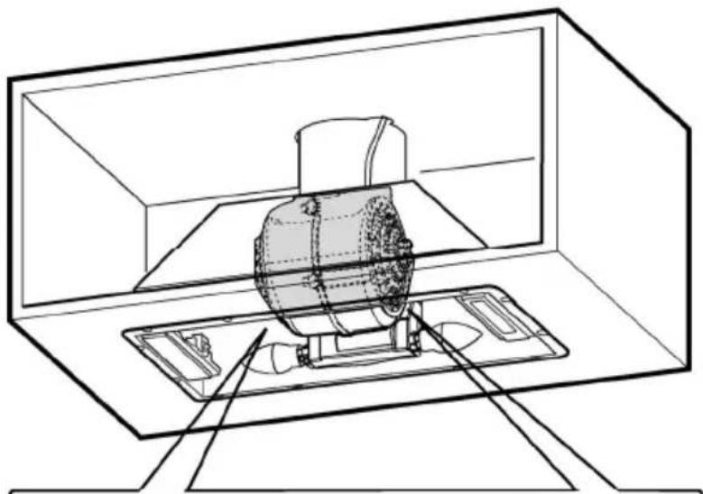
Fig. 1-7
The grease filter must be cleaned once a month using non aggressive detergents, either by hand or in the dishwasher, which must be set to a low temperature and a short cycle. When washed in a dishwasher, the grease filter may discolor slightly, but this does not affect its filtering capacity.
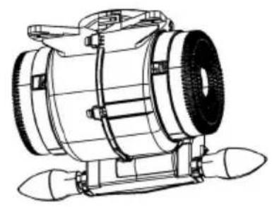
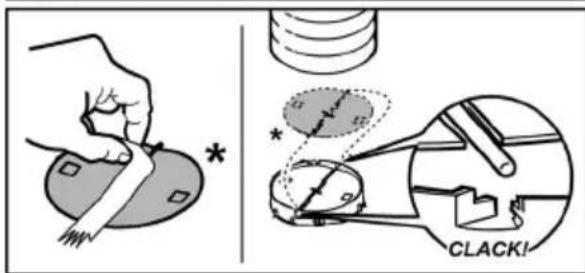
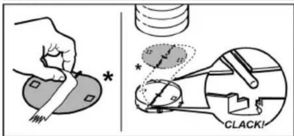
Charcoal filter (filter version only)
Fig. 5
The saturation of the charcoal filter occurs after more or less prolonged use, depending on the type of cooking and the regularity of cleaning of the grease filter.
In any case it is necessary to replace the cartridge at least every four months.
The charcoal filter may NOT be washed or regenerated.
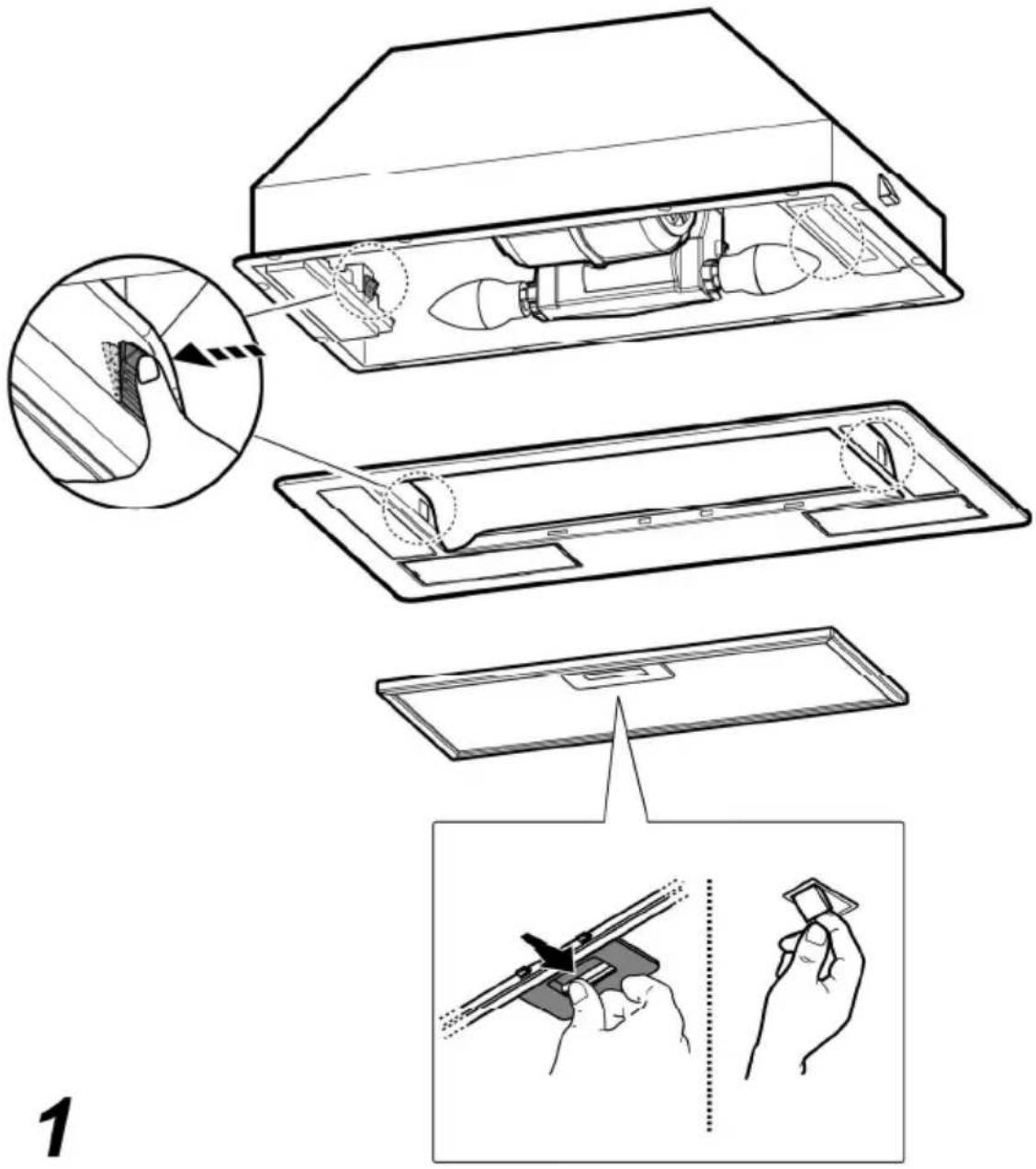
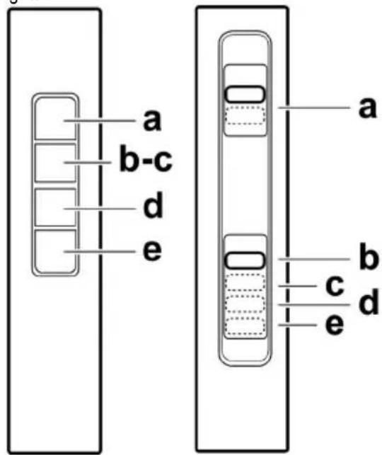
Replacing lamps
Fig.7
Disconnect the appliance from the electricity.
Warning! Prior to touching the light bulbs ensure they are cooled down.
Remove the suction gril to access the lamp area.
Replace the damaged lamp.
Use E14 3W max LED lamps only. For more details, check enclosed leaflet "ILCOS D" (alfanumeric position "1d").
If the lights do not work, make sure that the lamps are fitted properly into their housings before you call for technical assistance.
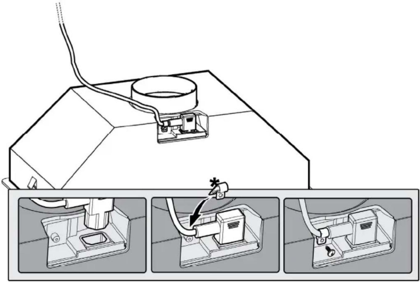
On some models ONLY:
A Non Return Backdraft Damper is included in the supply, as optional accessory to be installed under certain installation conditions (i.e. if there is no protection against accidental backdraft of air from the outside). The damper must be installed inside the dedicated housing, inside of the Air Outlet Fitting, before installing the flue.


SL - Navodila za montažo in uporabo

Strogo se pridržavajte uputstava koje donosi ovaj priručnik. Otklanjamo bilo kakvu odgovornost za eventualne nezgode, smetnje ili požar na aparatu koji proizlaze iz nepoštivanja uputstava koje donosi ovaj priručnik. Kuhinjska napa ima funkciju usisavanja dima i pare za vrijeme kuhanja te je namijenjena samo kućnoj uporabi.

استبideal المصابيح
شکل 7
natural_image
Diagram of a mechanical assembly with a cylindrical component and a circular component, showing internal structure (no text or symbols)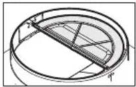
natural_image
Technical line drawing of a circular mechanical component with internal structural lines (no text or symbols)