
High-Bright Remote Monitor - Remote control screen DJI - Free user manual and instructions
Find the device manual for free High-Bright Remote Monitor DJI in PDF.

| Product Type | Remote Control Screen (High-Bright Wireless Monitor) |
| Brand | DJI |
| Model | High-Bright Remote Monitor (RXD2) |
| Dimensions (with expansion protector) | 214 × 52 × 166 mm |
| Weight (with expansion protector) | 768 g |
| Touchscreen Resolution | 1920 × 1200 |
| Brightness | 1500 cd/m² |
| Transmission System | DJI O3 Pro |
| Maximum Transmission Range | 6 km (FCC) / 4 km (CE, SRRC, MIC) |
| Latency | 68 ms (1080p 60 fps) |
| Compatible Batteries | DJI WB37 (included) ; NP-F series (via adapter) |
| Operating Temperature | -10°C to 40°C |
| MicroSD Card Capacity | Up to 512 GB |
| Ports | HDMI, USB-C, 3.5 mm audio output, microSD slot, DC/CAN input and HDMI/SDI output (via expansion plate) |
| Key Functions | Remote control, local recording, LUT display, exposure assist (zebras, waveform, false color), focus assist (peaking, LiDAR waveform), safety zone, image guide, gyroscope control, Control/Broadcast modes |
| Safety | Minimum distance of 15 cm from pacemakers; avoid use near sensitive medical devices. Body SAR: 0.02 W/kg. Compliance with CE, FCC, ISED. |
| Care and Cleaning | Clean with a soft, dry cloth. Do not use chemicals or abrasives. |
| Spare Parts and Repairability | Contact DJI support or an authorized service center. Spare parts (antennas, battery adapter, expansion plate) are available through the DJI network. |
| General Information | Model number: RXD2. Weight without protector: 496 g. Dimensions without protector: 184 × 26 × 158 mm. Frequency range: 2.4 GHz / 5.1-5.85 GHz (varies by region). |
Frequently Asked Questions - High-Bright Remote Monitor DJI
User questions about High-Bright Remote Monitor DJI
0 question about this device. Answer the ones you know or ask your own.
Ask a new question about this device
Download the instructions for your Remote control screen in PDF format for free! Find your manual High-Bright Remote Monitor - DJI and take your electronic device back in hand. On this page are published all the documents necessary for the use of your device. High-Bright Remote Monitor by DJI.
USER MANUAL High-Bright Remote Monitor DJI
DJI High-Bright Remote Monitor
User Guide
使用说明
使用说明
ユーザーガイド
사용자 가이드
Handbuch
Guía de usuario
Guide d'utilisateur
Guida per l'Utente
natural_image
Technical line drawing of a rectangular electronic device with four cylindrical ports and mounting brackets (no text or symbols)Contents
EN Disclaimer and Warning 1
Introduction 1
Overview 1
Mounting/Removing the Battery 2
Activation 4
Linking 4
Monitoring Interface 6
System Menu 12
Appendix 14
Disclaimer and Warning
Carefully read this entire document and all safe and lawful practices provided before use.
Introduction
Boasting DJI's O3 Pro Video Transmission technology, the DJI ^TM High-Bright Remote Monitor can connect wirelessly to compatible devices when used with the Ronin 4D Video Transmitter or DJI Video Transmitter. The monitor enables users to follow the live view of the camera and to control the camera remotely. An expansion plate can be mounted to the monitor to expand the DC and CAN input and HDMI and SDI output. The hand grip ports on the remote monitor expansion-protective frame can be used to mount the grips for remote control. The remote monitor supports DJI WB37 batteries and also NP-F series batteries when used with the NP-F battery adapter.
Overview
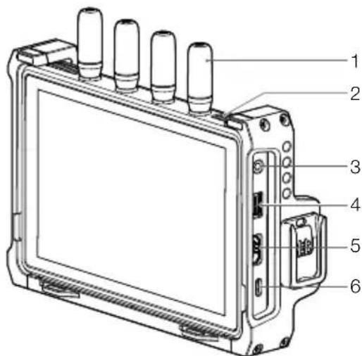
- Detachable Antennas
- Ventilation Holes
- 3.5mm Audio Output Jack
Monitors the audio recorded by the transmitter device when a monitoring device is connected.
- microSD Card Slot
The slot supports a microSD card of up to 512 GB. The remote monitor supports local recording and can play the recording files independently of the transmitter device. Users can set to save the recorded files to the microSD card in the Recording Device setting.
- HDMI Port
The remote monitor can be used as an independent monitor when not used with a video transmitter. The video input signal can be received through the HDMI port and the frame guide and safety zone settings, exposure assistant, and focus assistant are available.
- USB-C Port
Connect to the DJI Assistant 2 (Ronin Series) software using a USB-C cable for device activation and firmware update. The video stream from the monitor can be used as a
webcam input when connecting to a computer. It is required to set the usage of the USB-C port in the Input & Output Settings on the monitor before use.
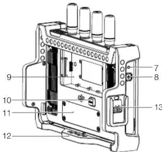
7. Power Indicator
The indicator will light up when powered on and will turn off when powered off.
8. Power Button
Press once to power on. When powered on, press the power button once to turn off the screen display. Press again to turn it on. Press the power button twice to lock the touch screen and all touch operations will be disabled. Press twice again to unlock the touch screen.
9. Battery Slot
The WB37 Intelligent Battery is used for power supply by default. The NP-F series batteries can be used for power supply when the NP-F battery adapter is mounted.
10. WB37 Battery Release Button
11. Expansion Plate Port Cover
The expansion plate port under the cover is used to mount the remote monitor expansion plate to expand the DC and CAN input and HDMI and SDI output.
12. Expansion-Protective Frame
Accessories can be mounted to the expansion-protective frame using the 1/4" screw holes, 1/8" screw holes, and hand grips port (13 on overview illustration).
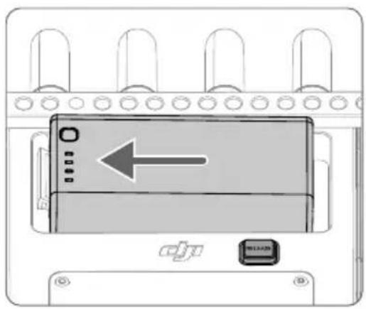
Mounting/Removing the Battery
Before first use, activate the WB37 battery by charging with the WB37 Battery Charging Hub (USB-C). Refer to the WB37 Battery Charging Hub (USB-C) User Guide for more information.
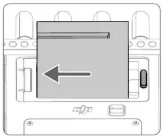
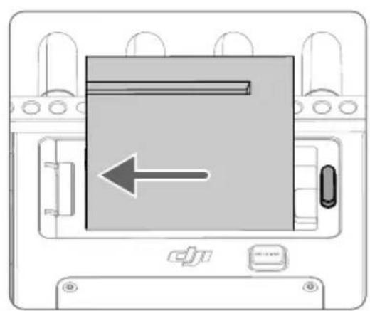
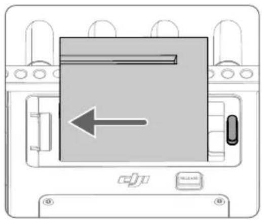
- Insert the WB37 battery into the battery slot and push it to the end. Make sure that the WB37 battery release button pops up, indicating the battery is firmly in place.
natural_image
Diagram of a device panel with an arrow pointing left, labeled 'djv' and 'WILLI' (no text or symbols on the device itself)Press and hold the WB37 battery release button and push the battery in the opposite direction to remove it.

Make sure to use the WB37 battery within the operating temperature range. DO NOT disassemble or pierce a battery in any way or it may leak, catch fire, or explode. Refer to the WB37 Intelligent Battery Safety Guidelines for more information.
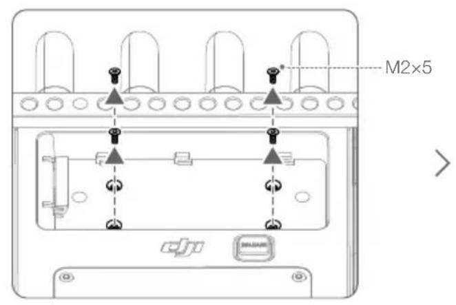
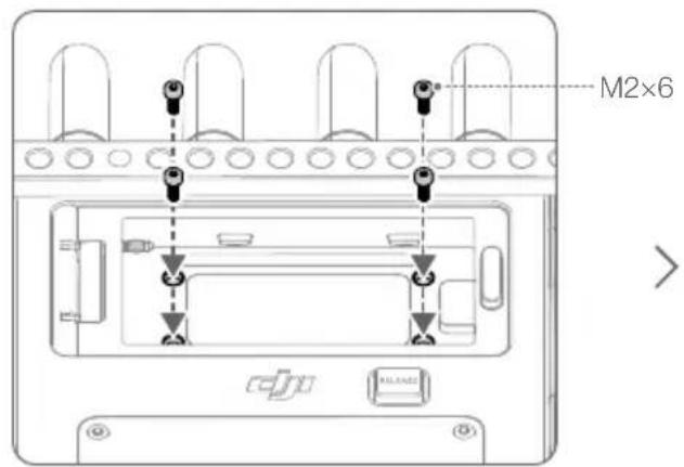
- When using the NP-F series batteries, remove the four M2×5 countersunk screws on the back of the remote monitor, mount the NP-F battery adapter to the battery slot, and tighten the four M2×6 socket cap screws. Insert the battery and push it to the end with the connector. Make sure that the NP-F battery release button pops up, indicating the battery is firmly in place.


natural_image
Diagram of a device with an arrow pointing to a rectangular component, no text or symbols presentPress and hold the battery release button on the battery adapter and push the battery in the opposite direction to remove it.
Activation
Activation is required when using the remote monitor for the first time. Power on the monitor and connect it to the computer. Launch DJI Assistant 2 (Ronin Series), click the corresponding device icon, and follow the instructions onscreen to activate the device. Download the software from:
https://www.dji.com/downloads/softwares/dji-assistant-2-ronin-series

Make sure to connect the device to the DJI Assistant 2 software and log in with your DJI account to make sure it is correctly recognized when the device is used in a country or region that is different from where it was activated.
Linking
The monitor and video transmitter must be linked before use. Make sure that the video transmitter is mounted to a compatible device before linking. The video transmission system of the remote monitor offers Control mode and Broadcast mode, which use different linking methods.
Control Mode
- Power on the remote monitor. Tap to enter System Menu and then Connection Settings. Select Control Mode, set the monitor as Control Monitor A or Control Monitor B, and tap Link to Control Monitor A/B to enter linking status.
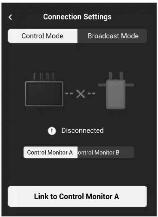
- Using Ronin 4D: to start linking, hold the link button on the Ronin 4D Video Transmitter or go to menus on the Ronin 4D High-Bright Main Monitor, tap Transmission, and Link Device. The linking status indicator on the video transmitter blinks red and green alternately, indicating the device is linking.
Using DJI Video Transmitter: power on the DJI Video Transmitter. Press and hold the menudial on the video transmitter until the linking status indicator blinks red and green alternately, indicating the device is linking.
- Once linked, the remote monitor will show a connected status, the control monitor A/B on the Ronin 4D main monitor will have a connected status, and the linking status indicator on the video transmitter will glow solid green.
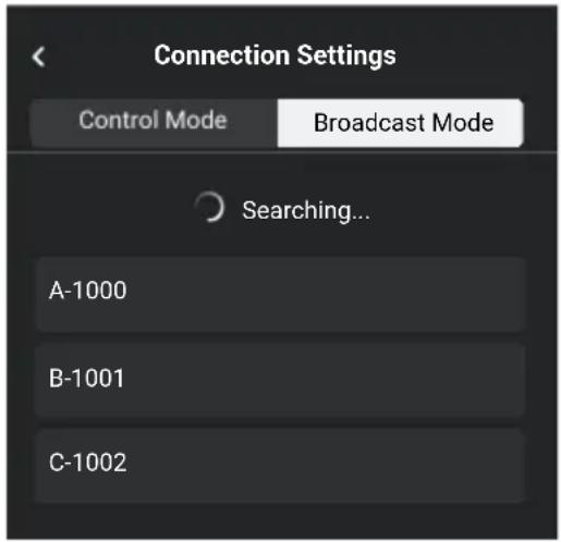
Broadcast Mode
- Using Ronin 4D: enable Broadcast Mode in Transmission settings on the Ronin 4D High-Bright Main Monitor. Make sure that at least one remote monitor is powered on and connected to Ronin 4D before enabling Broadcast mode.
Using DJI Video Transmitter: enable Broadcast mode in the menu on the video transmitter.
- Power on the remote monitor. Tap to enter System Menu and then Connection Settings. Select Broadcast Mode and the monitor will automatically search for nearby devices with Broadcast mode enabled. Tap a device to monitor and the live view from the corresponding device will display on the remote monitor. Tap the camera number on the right side of the screen to refresh the live view or switch between the monitored devices.
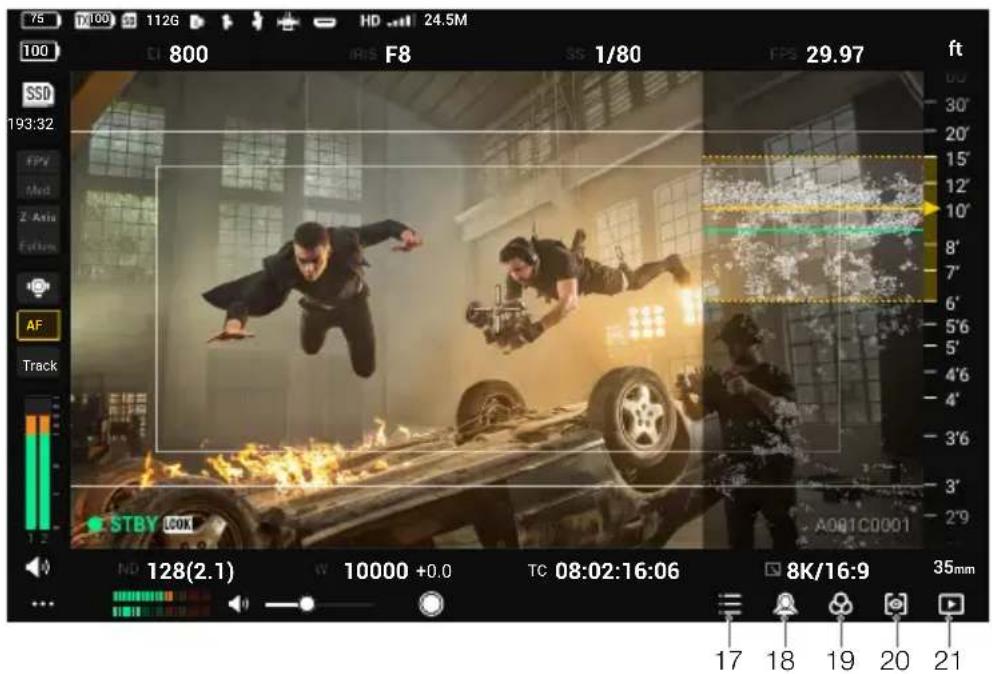
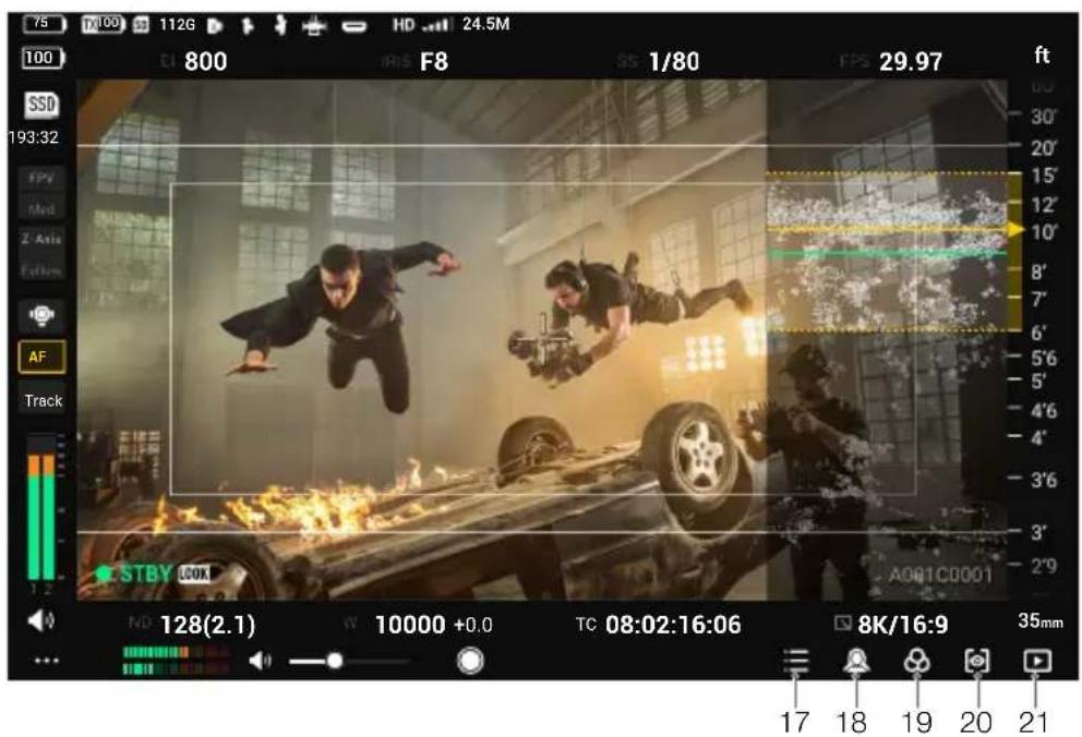
Monitoring Interface
E2

Control Mode
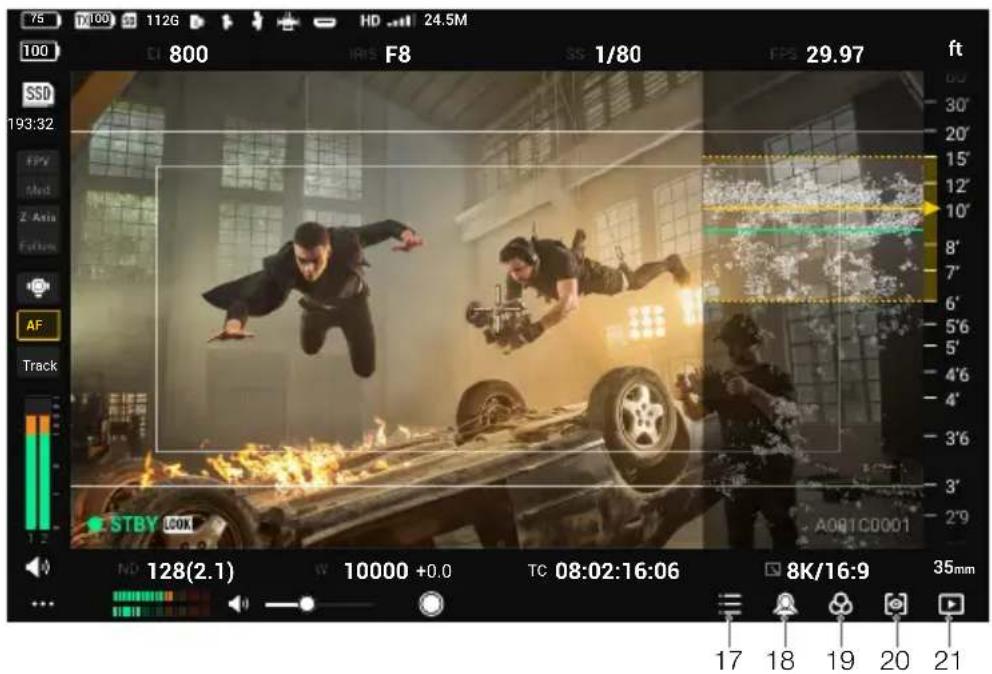
Mirror Control Mode on Ronin 4D Enabled
natural_image
Two performers in dynamic action poses inside a dimly lit theater with fire and vehicle damage (no visible text or symbols)Broadcast Mode
The interface varies for Control mode and Broadcast mode. The following describes the interface for Control mode. In Broadcast mode, operations such as adjusting recording parameters and switching LUT cannot be performed.
1. Battery Level and External Power Voltage
The battery level will be displayed when a battery is used as the power source, while the voltage will be displayed when an external DC power supply is used. The battery icon will turn red 10 when the battery level is lower than 10% . The battery icon will be □ when the battery level is critically low. Charge the battery immediately.
2. TX Battery Level and External Power Voltage
Displays the battery level or external power voltage of the transmitting device according to the device and power supply used.
3. Storage Capacity
Displays the available storage or the corresponding remaining recording time of the microSD card in the monitor.
4. Remote Control Devices
Shows the connected remote control devices. See below for the corresponding device for each icon.
: Three-Channel Follow Focus : Master Wheels
: Left Hand Grip : Right Hand Grip
5. HDMI Input Devices
This icon will appear when the HDMI port is connected to a video source.
6. Video Transmission Signal Strength and Bitrate
Tap to enter video transmission channel settings to switch the channel mode, check the signal quality, and select the channel and downlink bandwidth.
Channel Mode: tap to switch between Auto and Manual.
In Auto mode, channels with strong interference will be avoided automatically and the
channel with the least interference and best signal quality is selected. In Manual mode, users can manually select the channel with the best signal quality and downlink bandwidth. If the remote monitor is near connected devices in an environment with weak interference, it is recommended to set the bandwidth to 40M for best transmission quality. If the remote monitor is far from connected devices in an environment with strong interference, it is recommended to set the bandwidth to 20M for longer transmission distance and better anti-interference.
When using with the DJI Video Transmitter, if the video transmitter is linked to the remote monitor in Control mode and Broadcast mode is enabled, users can select the prioritized mode.
Prioritized Mode: tap to select Control mode or Broadcast mode as the prioritized mode.
When Control mode is the prioritized mode, the transmission signal quality of the devices in Control mode will have a priority. Users can select the channel mode. In this mode, devices in Broadcast mode near the remote monitor may have a weak transmission signal.
When Broadcast mode is the prioritized mode, the transmission signal quality of the devices in Broadcast mode will have a priority. Users can select the channel manually, while the channel mode and downlink bandwidth cannot be selected.
7. Recording Parameters
Recording parameters will be displayed when used with Ronin 4D including white balance, ND, aperture, EI, and aperture angle or shutter speed (depending on Ronin 4D settings). Tap to adjust the corresponding parameter.
8. Gyroscope Control
Tap to enter the settings menu to enable or disable Gyroscope Control. When enabled, set the follow speed of the pan, tilt, and roll axes, and recenter the gimbal. Enter the advanced settings to set the deadband and smoothness of the pan, tilt, and roll axes, calibrate the compass, and reset to default.
When Gyroscope Control is enabled, hold this icon to pause control and the gimbal will keep the current attitude. Release to resume control. Double tap the icon to recenter the gimbal.

- The Gyroscope Control icon will not appear here if Gyroscope Control is disabled in System Menu.
- LiDAR waveform will not appear when Gyroscope Control is enabled.
9. Safety Zone
The safety zone can be used to assist in composition and also to reserve space for overlaid information in advance such as TV station logos and program icons that need to be added to the video. Users can enable or disable the safety zone and set the safety zone ratio in General Settings. Note that the safety zone ratio is only a reference for monitoring and will not affect the actual recording.
10. Frame Guide
Shows the pre-set frame guide. Users can select the frame guide ratio and transparency in General Settings. Frame guide ratio customization is not supported at the moment. Note that the frame guide ratio is only a reference for monitoring and will not affect the actual recording.
11. System Menu
Includes connection settings, general settings, local playback, about, and help. Refer to the System Menu section for details.
12. Volume Level
Shows the current volume level. Green means the volume is safe, yellow means it is approaching being overloaded, and red means it is overloaded.
13. Monitor Volume
Move the slider to adjust the volume from the 3.5mm audio output jack. The remote monitor does not have a built-in speaker. Users can only monitor the volume using the 3.5mm audio output jack.
14. Recording Button and Timecode
Tap to start or stop recording locally or remotely. The icon to the right of the timecode shows the recording device in control currently. Users can select the device in the recording device setting.
15. LUT (for Ronin 4D only)
Tap to switch the LUT effect of the SDI and HDMI video output from the remote monitor or remote monitor expansion plate to Rec.709, D-log, HLG, and LOOK. To customize LUT for monitoring, set the function for LOOK in the Ronin 4D High-Bright Main Monitor to the imported custom LUT. Refer to the Ronin 4D User Manual for more information.
16. Exposure Assist/Focus Assist Settings
Focus Meter: when enabled, the focus meter will be displayed on the right of the screen. It can be used to assist focus when the Ronin 4D Hand Grips or DJI Three-Channel Follow Focus is used. The focus plane distance (the yellow arrow pointed to) and depth of field (area within yellow dotted lines) can be displayed in the focus meter and LiDAR waveform when the focus point information and aperture value are read. (for Ronin 4D only)
LiDAR Waveform: when enabled, the ranging points within the focus area of the LiDAR range finder will be displayed on the right of the screen in a simplified top-down view. (for Ronin 4D only)
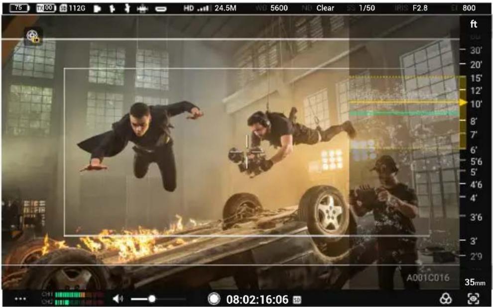
LiDAR Waveform Effect Image
Zebra Stripes: when enabled, the overexposed areas in the image will be displayed in zebra stripes. Adjust the percentage of the zebra level using the slider under the option.

Zebra Stripes Effect Image
Waveform: when enabled, the bottom of the screen will show the relationship and degree of the light and shadow in the current screen with a waveform.
Waveform Effect Image
False Color: when enabled, colors representing exposure values of different objects will be added to the image. Enable false color reference to display the false color chart at the bottom of the screen.
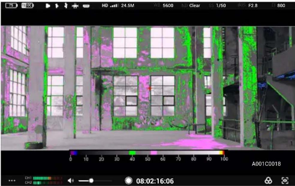
natural_image
Interior view of an industrial facility with large windows and green-tinted walls, captured via thermal imaging software (no readable text or symbols)False Color Effect Image
Focus Peaking: when enabled, users can set the display color and percentage for color peaking or the percentage for aperture peaking.
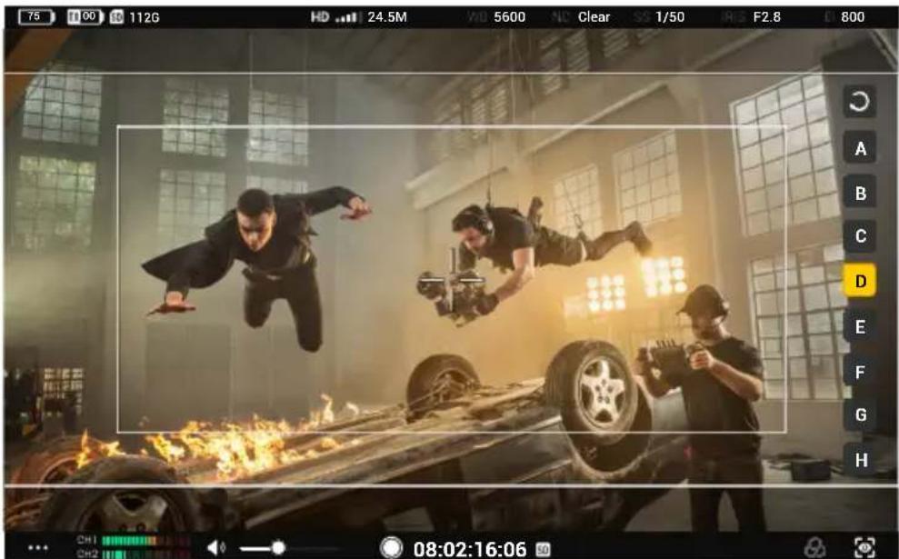
When Mirror Control mode is enabled in the Ronin 4D main monitor, users can access the complete live view of the Ronin 4D main monitor on the remote monitor and adjust the parameters. The touch operations on the live view are the same as those on the Ronin 4D main monitor. The icons below correspond to the physical buttons on the Ronin 4D main monitor. Tap the icons on the screen to perform the same functions of the buttons.
17. Home Button
Tap to enter the menu screen.
18. Focus Peak Button
Tap to enable or disable the focus assist display. The function is set to Focus Peaking by default. Go to the menu, select Display, then Focus Assistant, and set the PEAK Button Function to LiDAR Waveform and Focus Mag. The function of the icon on the screen of the remote monitor will be updated accordingly.
19. LUT Button
Tap to enable or disable LUT display. LUTs are customizable. Go to the menu and select Display then LOOK to set LOOK as an imported custom LUT. Refer to the LOOK section in the Ronin 4D User Manual for more information.
20. EXP Button
Tap to enable or disable the exposure display. The feature supports Zebra Stripes, Waveform, and False Color. Go to the menu and select Display then Exposure Assistant to apply settings.
21. Playback Button
Tap to access playback and play the last recorded video.
System Menu
Tap on the bottom left to enter the system menu for multiple settings.
Connection Settings
Link devices and switch between Control mode and Broadcast mode.
General Settings
Input & Output Settings
HDMI/SDI OSD: enable or disable on-screen display on the HDMI/SDI output device.
HDMI/SDI Aspect Ratio: Normal or CenterCrop (16:9).
HDMI/SDI Frame Rate: Auto or 24/25/30/50/60. When an HDMI/SDI output device is connected, the monitor will also prompt a window for frame rate selection. Low latency is selected by default, corresponding to the option 60 in this setting. Auto corresponds to the option Auto in this setting.

The DJI Remote Monitor Expansion Plate is required when using HDMI/SDI output functions.
Input Signal: select OcuSync when using the transmitter as the input source. Select HDMI when using the HDMI port on the monitor as the input source.
Rec Trigger: when a camera with the rec trigger function is used for the transmitter device, enable or disable the function in this setting.
USB-C Function: select Update when using the USB-C port for firmware update. If Webcam is selected, the video stream from the monitor can be used as a webcam input and uploaded to the computer connected to the USB-C port.
Recording Device
Select the device for video recording.
TX+SD: when using with Ronin 4D, control both the monitor and Ronin 4D to record videos simultaneously by the record button on the monitoring interface of the monitor or on Ronin 4D. The recorded files will be stored to both the storage device on Ronin 4D and the microSD card in the monitor.
TX: when using with Ronin 4D, control Ronin 4D to record videos by the record button on the monitoring interface of the monitor or on Ronin 4D. The monitor will not perform local recording. The recorded files will be stored to the storage device on Ronin 4D.
SD: control local recording by the record button on the monitoring interface of the monitor. The transmitter device will not perform recording. The recorded files will be stored to the microSD card in the monitor.
Storage
Tap to view the free storage of the microSD card in the monitor and format the microSD card.
Gyroscope Control
Enable or disable Gyroscope Control. The Gyroscope Control icon will not appear on the monitoring interface when Gyroscope Control is disabled.
Hand Grip Dial
This setting will appear only when using with DJI Video Transmitter. Set the function of the dial on the right hand grip if the Ronin 4D Hand Grip is mounted to the monitor.
Screen Settings
Set the frame guide ratio and transparency, enable or disable the safety zone and center marker, and set the safety zone ratio and brightness.
When an anamorphic widescreen lens is in use, set the appropriate anamorphic desqueeze display ratio to restore the monitoring liveview to the normal effect.
When specific cameras are in use with the transmitter device, enable the virtual widget to set the camera parameters using the virtual buttons on the monitor screen.
Language
Select the system language in the language list.
Local Playback
View and play the locally recorded videos on the microSD card in the playback view.
The monitor will play the last recorded video automatically after entering the playback view. Tap to view the video list. Tap <to return to the monitoring interface.
About and Help
View information such as the firmware version and serial number under About and scan the QR code to view the video tutorials under Help.
Appendix
Firmware Update
Update the monitor using the DJI Assistant 2 (Ronin Series) software.
- Power on the device and connect it to a computer with a USB-C cable.
- Launch DJI Assistant 2 (Ronin Series) and log in with a DJI account.
- Select the device and click Firmware Update on the left side of the screen.
- Select the firmware version.
- The firmware will be downloaded and updated automatically.
- The device will restart automatically after the firmware update is complete.
Specifications
| Model RXD2 | |
| Weight | Remote monitor expansion-protective frame included: 768 gRemote monitor expansion-protective frame excluded: 496 g |
| Dimensions | Remote monitor expansion-protective frame included: 214×52×166 mm (L×W×H)Remote monitor expansion-protective frame excluded: 184×26×158 mm (L×W×H) |
| Touchscreen Resolution 1920×1200 | |
| Touchscreen Brightness 1500 cd/m | 2 |
| Image Transmission System O3 Pro | |
| Live View Quality 1080p 60fps | |
| Max Communication Bandwidth 40 MHz | |
| Max Transmission Distance (Unobstructed, free of interference) | 6 km (FCC), 4 km (CE/SRRC/MIC) |
| Video Coding Format H.264 | |
| Max Bitrate 40 Mbps | |
| Latency 68 ms (1080p 60fps), 100 ms (1080p 24fps) | |
| Operating Frequency* | 2.4000-2.4835 GHz, 5.150-5.250 GHz, 5.250-5.350 GHz, 5.470-5.725 GHz, 5.725-5.850 GHz |
| Transmitter Power (EIRP) | 2.4 GHz: <33 dBm (FCC), <20 dBm (CE/SRRC/MIC)5.8 GHz: <33 dBm (FCC), <14 dBm (CE), <23 dBm (SRRC) |
| Supported Batteries WB37 Intelligent Battery, NP-F series battery | |
| Operating Temperature -10° to 40°C (14° to 104°F) | |
* Due to local regulations, the 5.1/5.2/5.8GHz frequencies are prohibited in some countries and the 5.1/5.2GHz frequencies are only allowed for use in indoor in some countries. 5.600-5.650 GHz is not used.
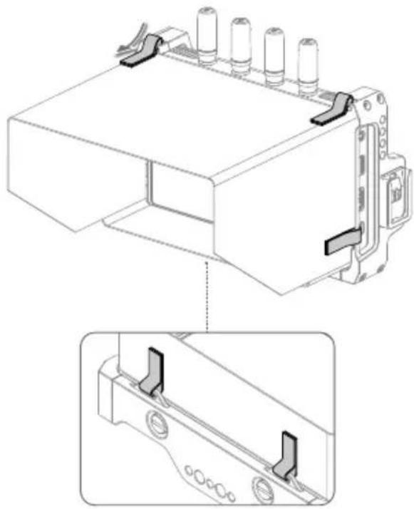
Mounting the Remote Monitor Hood
Unfold the remote monitor hood, pass the Velcro on the hood through the mounting holes on the remote monitor expansion-protective frame as shown, and attach the Velcro firmly.
natural_image
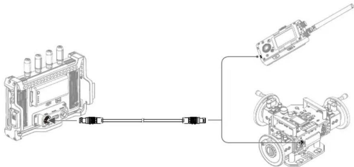
Technical line drawing of a mechanical component with mounting holes and a close-up view (no text or symbols)Using Other Control Devices
Connect the DJI Master Wheels or Force Pro to the monitor to control the transmitter device remotely.
Connection: mount the DJI Remote Monitor Expansion Plate to the monitor. Connect the DC-OUT port on the DJI Master Wheels or Force Pro to the DC-IN port on the expansion plate using the DJI High-Bright Remote Monitor Controller Cable.
natural_image
Technical line drawing showing a device connected to a motor via cable, with no visible text or symbols.免责声明和警告

natural_image
Diagram of a device panel with an arrow pointing to it, no text or symbols present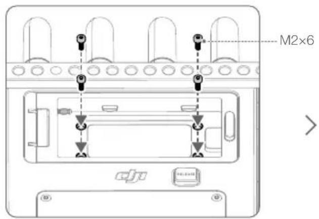
natural_image
Diagram of a device with an arrow pointing to a rectangular block, no text or symbols presenthttps://www.dji.com/downloads/softwares/dji-assistant-2-ronin-series

natural_image
Two performers in dynamic action poses over a burning vehicle, captured in a studio setting with no visible text or symbols.广播模式
natural_image
Technical line drawing of a mechanical component with mounting holes and a close-up view (no text or symbols)使用其他控制设备
natural_image
Technical line drawing showing a device connected to a motor via cable, with no visible text or symbols.免責聲明和警告

natural_image
Diagram of a device panel with an arrow pointing left, mounted on a base with a button labeled 'DJ' (no text or symbols beyond basic labels)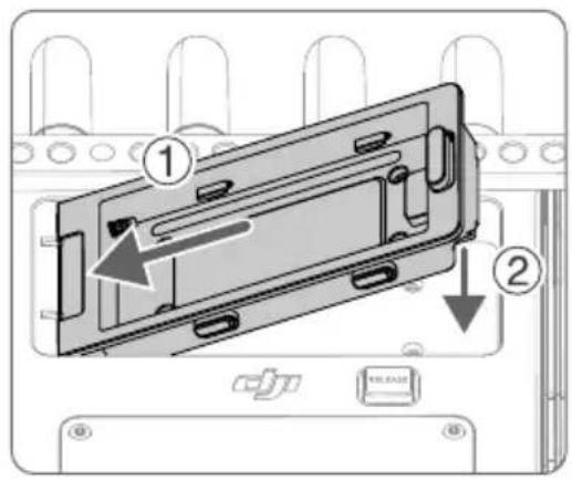


natural_image
Diagram of a device with an arrow pointing to a rectangular block, no text or symbols presenthttps://www.dji.com/downloads/softwares/dji-assistant-2-ronin-series

natural_image
Action scene from a superhero film showing two acrobats mid-air above a burning car, with no visible text or symbols.廣播模式
natural_image
Movie scene from A001C016 showing two superhero characters in dynamic mid-air above a burning vehicle, with no visible text or symbols.LiDAR 示波器效果示意圖
natural_image
Technical line drawing of a mechanical component with mounting holes and a close-up view (no text or symbols)使用其他控制装置
免責事項および警告
natural_image
Diagram of a device with an arrow pointing left, mounted on a base panel (no text or symbols)


natural_image
Diagram of a device with an arrow pointing to a rectangular block, labeled 'CJU' and 'TILLIANT' (no readable text or symbols beyond labels)https://www.dji.com/downloads/softwares/dji-assistant-2-ronin-series

モニター画面

制御モード

natural_image
Two performers in dynamic action poses inside a dimly lit theater, with fire and smoke visible (no readable text or symbols)配信モード
natural_image
Interior view of an unfinished building with large windows and green-tinted lighting (no readable text or symbols)ウェーブフォーム効果の画像
natural_image
Technical line drawing of a mechanical component with mounting brackets and a close-up view (no text or symbols)他の制御デバイスの使用
고지 사항 및 경고

natural_image
Diagram of a device panel with an arrow pointing left, mounted on a base with a button labeled 'MILK' (no text or symbols beyond basic labels)
natural_image
Diagram of a device with an arrow pointing to a rectangular component, no text or symbols presenthttps://www.dji.com/downloads/softwares/dji-assistant-2-ronin-series

모니터링 인터페이스
natural_image
Action scene from a superhero film showing two acrobats mid-air above a burning car, with no visible text or symbols.natural_image
Action scene from video editing software showing two superhero characters mid-air above a burning vehicle, with no visible text or symbols.LiDAR 파형 효과 이미지
natural_image
Technical line drawing of a mechanical component with mounting brackets and a close-up view (no text or symbols)기타 컨트롤 기기 사용

natural_image
Diagram of a device panel with an arrow pointing left, mounted on a base with a USB port and indicator lights (no text or symbols present)

natural_image
Diagram of a device with a left-pointing arrow and control buttons, no readable text or symbols present.https://www.dji.com/downloads/softwares/dji-assistant-2-ronin-series

natural_image
Action scene from a superhero film showing two performers mid-air above a burning vehicle, with no visible text or symbols.natural_image
Action scene from a superhero movie showing three characters in dynamic mid-air above fire, with no visible text or symbols.natural_image
Interior view of an unfinished concrete building with patterned windows and a red arrow pointing to a small structure (no readable text or symbols)natural_image
Interior view of an industrial facility with large windows and green-tinted walls, captured via thermal imaging software (no readable text or symbols)natural_image
Technical line drawing of a mechanical component with mounting holes and a close-up view (no text or symbols)natural_image
Technical line drawing showing a device connected to a sensor and motor assembly (no text or symbols present)
natural_image
Diagram of a device panel with an arrow pointing left, no text or symbols present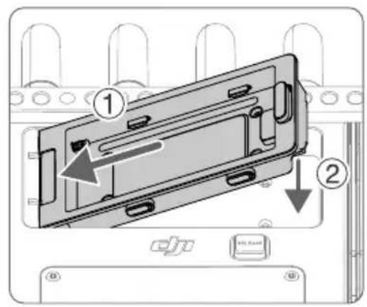

natural_image
Diagram of a device with a left-pointing arrow and control buttons (no readable text or symbols)https://www.dji.com/downloads/softwares/dji-assistant-2-ronin-series

natural_image
Two performers in dynamic action poses above a burning car, captured in mid-air with a camera crew member nearby (no visible text or symbols)Modo Emisión
natural_image
Interior view of an industrial facility with large windows and green-tinted walls, captured via thermal imaging software (no readable text or symbols)natural_image
Technical line drawing of a mechanical component with mounting holes and a close-up view (no text or symbols)natural_image
Technical line drawing showing a device connected to a sensor and motor assembly (no text or symbols present)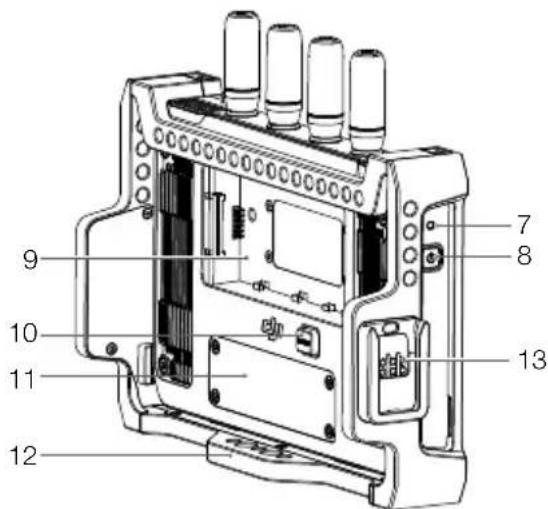
natural_image
Diagram of a device panel with an arrow pointing left, no text or symbols present

natural_image
Diagram of a device with an arrow pointing left, showing internal components and control buttons (no text or symbols)https://www.dji.com/downloads/softwares/dji-assistant-2-ronin-series

Interface de surveillance

Mode de contrôle
natural_image
Two performers in dynamic action poses above a burning car, captured in mid-air with a camera crew member nearby (no visible text or symbols)Mode Diffusion
natural_image
Interior view of a damaged industrial building with patterned windows and a red arrow pointing to a specific area (no readable text or symbols)Signal d'entrée: select OcuSync when using the transmitter as the input source. Select HDMI when using the HDMI port on the monitor as the input source.
natural_image
Technical line drawing of a mechanical component with mounting holes and a close-up view (no text or symbols)natural_image
Technical line drawing showing a device connected to a motor via cable, with no visible text or symbols.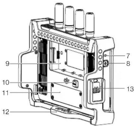
natural_image
Diagram of a device panel with an arrow pointing left, mounted on a base panel (no text or symbols present)

natural_image
Diagram of a device with an arrow pointing to a rectangular component, no text or symbols presenthttps://www.dji.com/downloads/softwares/dji-assistant-2-ronin-series

natural_image
Two performers in dynamic mid-air over a burning car, captured with camera crew and industrial background (no visible text or symbols)natural_image
Interior view of a damaged concrete structure with patterned windows and a red arrow pointing to a small object (no readable text or symbols)natural_image
Interior view of an unfinished building with large windows and a red cross marker, captured in a video editing interface (no readable text or symbols on the main scene)natural_image
Interior view of an industrial facility with large windows and green-tinted walls, captured via thermal imaging software (no readable text or symbols)natural_image
Technical line drawing of a mechanical component with mounting holes and a close-up view (no text or symbols)
natural_image
Diagram of a device panel with an arrow pointing left, labeled 'CJU' and 'HILLIAM' (no text or symbols on the device itself)

natural_image
Diagram of a device with a left-pointing arrow and control buttons, no readable text or symbols present.https://www.dji.com/downloads/softwares/dji-assistant-2-ronin-series

Bewakingsinterface

Besturingsmodus
natural_image
Two performers in dynamic action poses above a burning car, captured in mid-air with a camera crew member nearby (no visible text or symbols)Uitzendmodus
natural_image
Interior view of a damaged concrete structure with patterned windows and debris, captured in a video editing interface (no readable text or symbols on the main image area)natural_image
Interior view of an industrial facility with large windows and green-tinted walls, captured via a thermal imaging camera (no readable text or symbols)natural_image
Technical line drawing of a mechanical component with mounting holes and a close-up view (no text or symbols)
natural_image
Diagram of a device panel with an arrow pointing left, no text or symbols present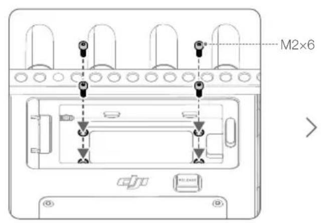
natural_image
Diagram of a device with a left-pointing arrow and control buttons, no readable text or symbols present.https://www.dji.com/downloads/softwares/dji-assistant-2-ronin-series

natural_image
Two performers in dynamic action poses above a burning car, captured in a dimly lit studio with no visible text or symbols.Modo de emissão
natural_image
Action scene from a superhero film showing two characters in mid-air during a fire, with a damaged vehicle and fire damage (no readable text or symbols)natural_image
Technical line drawing of a mechanical component with mounting holes and a close-up view (no text or symbols)
natural_image
Diagram of a device with an arrow pointing left, mounted on a base panel (no text or symbols)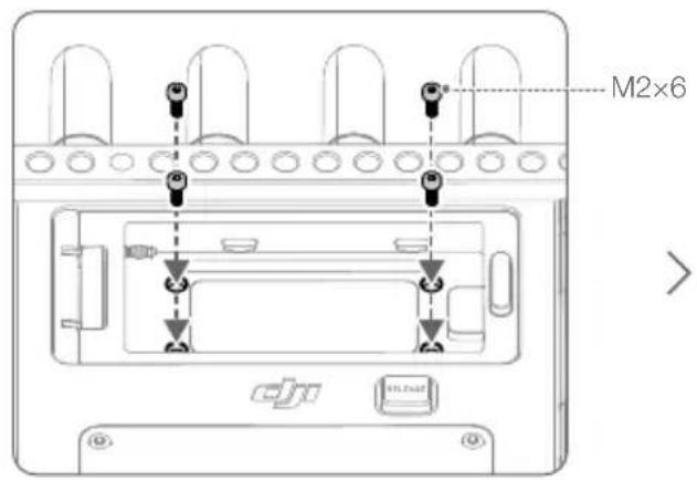
natural_image
Diagram of a device with an arrow pointing to a rectangular block, labeled 'CPU' and 'RELEASE' (no text or symbols on the diagram itself)https://www.dji.com/downloads/softwares/dji-assistant-2-ronin-series

natural_image
Action scene from a superhero film showing two leaping characters in dynamic poses above a burning car, with no visible text or symbols.natural_image
Action scene from a video editing interface showing two superhero characters mid-air above a burning car, with no visible text or symbols.natural_image
Technical line drawing of a mechanical component with mounting holes and a close-up view (no text or symbols)Compliance Information
FCC Compliance Notice
Supplier's Declaration of Conformity
Product name: DJI High-Bright Remote Monitor
Model Number: RXD2
Responsible Party: DJI Technology, Inc.
Responsible Party Address: 201 S. Victory Blvd., Burbank, CA 91502
Website: www.dji.com
We, DJI Technology, Inc., being the responsible party, declares that the above mentioned model was tested to demonstrate complying with all applicable FCC rules and regulations.
This device complies with Part 15 of the FCC Rules. Operation is subject to the following two conditions: (1) This device may not cause harmful interference, and (2) This device must accept any interference received, including interference that may cause undesired operation.
Any changes or modifications not expressly approved by the party responsible for compliance could void the user's authority to operate the equipment.
This equipment has been tested and found to comply with the limits for a Class B digital device, pursuant to part 15 of the FCC Rules. These limits are designed to provide reasonable protection against harmful interference in a residential installation. This equipment generates, uses and can radiate radio frequency energy and, if not installed and used in accordance with the instructions, may cause harmful interference to radio communications. However, there is no guarantee that interference will not occur in a particular installation. If this equipment does cause harmful interference to radio or television reception, which can be determined by turning the equipment off and on, the user is encouraged to try to correct the interference by one or more of the following measures:
—Reorient or relocate the receiving antenna.
—Increase the separation between the equipment and receiver.
—Connect the equipment into an outlet on a circuit different from that to which the receiver is connected.
—Consult the dealer or an experienced radio/TV technician for help.
BE Exposure Information
This equipment complies with FCC radiation exposure limits set forth for an uncontrolled environment. End user must follow the specific operating instructions for satisfying RF exposure compliance. This transmitter must not be co-located or operating in conjunction with any other antenna or transmitter.
The portable device is designed to meet the requirements for exposure to radio waves established by the Federal Communications Commission (USA). These requirements set a SAR limit of 1.6 W/kg averaged over one gram of tissue. The highest SAR value reported under this standard during product certification for use when properly worn on the body.
ISED Compliance Notice
This device contains licence-exempt transmitter(s)/receiver(s) that comply with Innovation, Science and Economic Development Canada's licence-exempt RSS(s). Operation is subject to the following two conditions: (1) This device may not cause interference.(2) This device must accept any interference, including interference that may cause undesired operation of the device.
This equipment complies with ISED radiation exposure limits set forth for an uncontrolled environment. End user must follow the specific operating instructions for satisfying PF exposure compliance. This transmitter must not be co-located or operating in conjunction with any other antenna or transmitter. The portable device is designed to meet the requirements for exposure to radio waves established by the ISED.
No operation is permitted for the frequency "5600-5650MHz"
These requirements set a SAR limit of 1.6 W/kg averaged over one gram of tissue. The highest SAR value reported under this standard during product certification for use when properly worn on the body.
For devices with detachable antenna(s), the maximum antenna gain permitted for devices in the bands 5250-5350 MHz and 5470-5725 MHz, 5725-5850 MHz shall be such that the equipment still complices with the o.i.r.p. limit as appropriate.
KCC Compliance Notice
NCC Compliance Notice
EU Compliance Statement: SZ DJI Osmo Technology Co., Ltd. hereby declares that this device (DJI High-Bright Remote Monitor) is in compliance with the essential requirements and other relevant provisions of the Directive 2014/53/EU.
A copy of the EU Declaration of Conformity is available online at www.dji.com/euro-compliance. EU contact address: DJI GmbH, Industriestrasse 12, 97618, Niederlauer, Germany
GB Compliance Statement: SZ DJI Osmo Technology Co., Ltd. hereby declares that this device (DJI High-Bright Remote Monitor) is in compliance with the essential requirements and other relevant provisions of Radio Equipment Regulations 2017.
A copy of the GB Declaration of Conformity is available online at www.dji.com/euro-compliance
Environmentally friendly disposal

Old electrical appliances must not be disposed of together with the residual waste, but have to be disposed of separately. The disposal at the communal collecting point via private persons is for free. The owner of old appliances is responsible to bring the appliances to these collecting points or to similar collection points. With this little personal effort, you contribute to recycle valuable raw materials and the treatment of
toxic substances.
This device is restricted to indoor use when operating in the 5150-5350MHz frequency range in all EU/EFTA member states, Türkiye and UK.
The terms HDMI, HDMI High-Definition Multimedia Interface, and the HDMI Logo are trademarks or registered trademarks of HDMI Licensing Administrator, Inc.
Download the latest version from
https://www.dji.com/transmission/downloads
※ This content is subject to change without prior notice.
If you have any questions about this document, please contact
DJI by sending a message to DocSupport@dji.com.

is a trademark of DJI.
Copyright © 2022 DJI All Rights Reserved.
- DJI High-Bright Remote Monitor
- Contents
- Disclaimer and Warning
- Introduction
- Overview
- Power Indicator
- Power Button
- Battery Slot
- WB37 Battery Release Button
- Expansion Plate Port Cover
- Expansion-Protective Frame
- Mounting/Removing the Battery
- Activation
- Linking
- Control Mode
- Broadcast Mode
- Monitoring Interface
- Battery Level and External Power Voltage
- TX Battery Level and External Power Voltage
- Storage Capacity
- Remote Control Devices
- HDMI Input Devices
- Video Transmission Signal Strength and Bitrate
- Recording Parameters
- Gyroscope Control
- Safety Zone
- Frame Guide
- System Menu
- Volume Level
- Monitor Volume
- Recording Button and Timecode
- LUT (for Ronin 4D only)
- Exposure Assist/Focus Assist Settings
- Home Button
- Focus Peak Button
- LUT Button
- EXP Button
- Playback Button
- System Menu
- Connection Settings
- General Settings
- Input & Output Settings
- Recording Device
- Storage
- Gyroscope Control
- Hand Grip Dial
- Screen Settings
- Language
- Local Playback
- About and Help
- Appendix
- Firmware Update
- Mounting the Remote Monitor Hood
- Using Other Control Devices
- 免责声明和警告
- 使用其他控制设备
- 免責聲明和警告
- 使用其他控制装置
- 免責事項および警告
- モニター画面
- 他の制御デバイスの使用
- 고지 사항 및 경고
- 기타 컨트롤 기기 사용
- Compliance Information
- FCC Compliance Notice
- BE Exposure Information
- ISED Compliance Notice
- KCC Compliance Notice
- NCC Compliance Notice
- Environmentally friendly disposal
Brand : DJI
Model : High-Bright Remote Monitor
Category : Remote control screen