PE 150 18.0-EC - Grinder Flex - Free user manual and instructions
Find the device manual for free PE 150 18.0-EC Flex in PDF.

User questions about PE 150 18.0-EC Flex
0 question about this device. Answer the ones you know or ask your own.
Ask a new question about this device
Download the instructions for your Grinder in PDF format for free! Find your manual PE 150 18.0-EC - Flex and take your electronic device back in hand. On this page are published all the documents necessary for the use of your device. PE 150 18.0-EC by Flex.
USER MANUAL PE 150 18.0-EC Flex
natural_image
Illustration of a power tool with two different components, no text or symbols presentde Originalbetriebsanleitung 3
en Original operating instructions 15
fr Notice d'instructions d'origine 26
it Istruzioni per l'uso originali 38
es Instrucciones de funcionamiento originales ..... 50
pt Instruções de serviço originais 62
nl Originele gebruiksaanwijzing 74
da Originale driftsvejledning 86
no Originale driftsanvisningen 97
sv Originalbruksanvisning 107
fi Alkuperäinen käyttöohjekirja 117
el Auθεντικές οδηγίες χειρισμού 128
tr Orijinal işletme kılavuzu 140
pI Instrukcja oryginalna 151
hu Eredeti üzemeltetési útmutató 163
cs Originální návod k obsluze 175
sk Originálny návod na obsluhu 186
hr Originalna uputa za rad 198
sl Izvirno navodilo za obratovanje 209
ro Instructiuni de functionare originale 220
bg Оригинално упътване за експлоатация ..... 231
ru Оригинальная инструкция по эксплуатации ..... 243
et Originaalkasutusjuhend 255
It Originali naudojimo instrukcija 266
Iv Lietošanas pamācības oriģināls 277
ar 297 ترجمة لارشادات الأتشغيل الأصلية
Inhalt
Verwendete Symbole 3
Symbole am Gerät 3
text_image
Technical diagram showing two mechanical components with numbered callouts indicating step-by-step assembly or installation.natural_image
Close-up of a car's side profile with a circular component and directional arrow, no visible text or symbolsnatural_image
Close-up of a car's side panel with circular components and an arrow pointing to a circular symbol (no text or labels)text_image
CA 10.8/18.0natural_image
Technical illustration of a device's internal components, showing two views of the casing with ventilation grilles and adjustment arrows (no text or symbols)Peter Lameli Technical Head

text_image
Bolts Q - 1Klaus Peter Weinper Head of Quality Department (QD)
15.12.2020
Symbols used in this manual ..... 15
For your safety 15
For your safety 15
Noise and vibration 17
Technical specifications 18
Overview 19
Operating instructions ..... 20
Maintenance and care 24
Disposal information 24
C€Declaration of Conformity ..... 25
UKCA Declaration of Conformity ..... 25
Exemption from liability 25
Symbols used in this manual
WARNING!
Denotes impending danger. Non-observance of this warning may result in death or extremely severe injuries.
CAUTION!
Denotes a possibly dangerous situation. Non-observance of this warning may result in slight injury or damage to property.
i NOTE
Denotes application tips and important information.
Symbols on the power tool

To reduce the risk of injury, read the operating instructions!

Wear goggles!

Disposal information for the old machine (see page 24)!
For your safety
WARNING!
Before using the power tool, please read and follow:
– these operating instructions,
- the "General safety instructions" on the handling of power tools in the enclosed booklet (leaflet-no.: 315.915),
– the currently valid site rules and the regulations for the prevention of accidents.
This power tool is state of the art and has been constructed in accordance with the acknowledged safety regulations.
Nevertheless, when in use, the power tool may be a danger to life and limb of the user or a third party, or the power tool or other property may be damaged.
The polisher may be used only
- as intended,
- in perfect working order.
Faults which impair safety must be repaired immediately.
Intended use
The polisher is designed
– for commercial use in industry and trade,
– for all types of polishing work with polishing sponges, lambskins and woolskins, felt plate, buffing disc,
– for use with polishing tools which are permitted to run at a speed of at least 1500 r.p.m.
Safety instructions for polishing
WARNING!
Read all safety warnings, instructions, illustrations and specifications provided with this power tool. Failure to follow all instructions listed below may result in electric shock, fire and/or serious injury. Save all warnings and instructions for future reference.
■ This power tool is intended to function as a polisher. Read all safety warnings, instructions, illustrations and specifications provided with this power tool.
Failure to follow all instructions listed below may result in electric shock, fire and/or serious injury.
■ Operations such as grinding, sanding, wire brushing, or cutting-off are not recommended to be performed with this power tool.
Operations for which the power tool was not designed may create a hazard and cause personal injury.
■ Do not use accessories which are not specifically designed and recommended by the tool manufacturer.
Just because the accessory can be attached to your power tool, it does not assure safe operation.
■ The rated speed of the accessory must be at least equal to the maximum speed marked on the power tool.
Accessories running faster than their rated speed can break and fly apart.
■ The outside diameter and the thickness of your accessory must be within the capacity rating of your power tool.
Incorrectly sized accessories cannot be adequately guarded or controlled.
- Threaded mounting of accessories must match the grinder spindle thread. For accessories mounted by flanges, the arbour hole of the accessory must fit the locating diameter of the flange.
Accessories that do not match the mounting hardware of the power tool will run out of balance, vibrate excessively and may cause loss of control.
■ Do not use a damaged accessory. Before each use inspect the accessory such as abrasive wheels for chips and cracks, backing pad for cracks, tear or excess wear, wire brush for loose or cracked wires. If power tool or accessory is dropped, inspect for damage or install an undamaged accessory. After inspecting
and installing an accessory, position yourself and bystanders away from the plane of the rotating accessory and run the power tool at maximum no-load speed for one minute.
Damaged accessories will normally break apart during this test time.
■ Wear personal protective equipment.
Depending on application, use face shield, safety goggles or safety glasses. As appropriate, wear dust mask, hearing protectors, gloves and shop apron capable of stopping small abrasive or workpiece fragments.
The eye protection must be capable of stopping flying debris generated by various operations. The dust mask or respirator must be capable of filtrating particles generated by your operation.
Prolonged exposure to high intensity noise may cause hearing loss.
- Keep bystanders a safe distance away from work area. Anyone entering the work area must wear personal protective equipment.
Fragments of workpiece or of a broken accessory may fly away and cause injury beyond immediate area of operation.
■ Position the cord clear of the spinning accessory. If you lose control, the cord may be cut or snagged and your hand or arm may be pulled into the spinning accessory.
■ Never lay the power tool down until the accessory has come to a complete stop. The spinning accessory may grab the surface and pull the power tool out of your control.
■ Do not run the power tool while carrying it at your side.
Accidental contact with the spinning accessory could snag your clothing, pulling the accessory into your body
■ Regularly clean the power tool's air vents. The motor's fan will draw the dust inside the housing and excessive accumulation of powdered metal may cause electrical hazards.
■ Do not operate the power tool near flammable materials.
Sparks could ignite these materials.
■ Do not use accessories that require liquid coolants.
Using water or other liquid coolants may result in electrocution or shock.
Kickback and Related Warnings:
Kickback is a sudden reaction to a pinched or snagged rotating wheel, backing pad, brush or any other accessory. Pinching or snagging causes rapid stalling of the rotating accessory which in turn causes the uncontrolled power tool to be forced in the direction opposite of the accessory's rotation at the point of the binding. For example, if an abrasive wheel is snagged or pinched by the workpiece, the edge of the wheel that is entering into the pinch point can dig into the surface of the material causing the wheel to climb out or kick out. The wheel may either jump toward or away from the operator, depending on direction of the wheel's movement at the point of pinching. Abrasive wheels may also break under these conditions. Kickback is the result of power tool misuse and/or incorrect operating procedures or conditions and can be avoided by taking proper precautions as given below.
■ Maintain a firm grip on the power tool and position your body and arm to allow you to resist kickback forces.
Always use auxiliary handle, if provided, for maximum control over kickback or torque reaction during start-up.
The operator can control torque reactions or kickback forces, if proper precautions are taken.
■ Never place your hand near the rotating accessory.
Accessory may kickback over your hand.
■ Do not position your body in the area where power tool will move if kickback occurs.
Kickback will propel the tool in direction opposite to the wheel's movement at the point of snagging.
■ Use special care when working corners, sharp edges etc. Avoid bouncing and snagging the accessory.
Corners, sharp edges or bouncing have a tendency to snag the rotating accessory and cause loss of control or kickback.
Safety Warnings Specific for Polishing Operations:
■ Do not allow any loose portion of the polishing bonnet or its attachment strings to spin freely. Tuck away or trim any loose attachment strings. Loose and spinning attachment strings can entangle your fingers or snag on the workpiece.
Additional safety instructions
■ Do not press the spindle lock until the tool stops.
Noise and vibration
The noise and vibration values have been determined in accordance with EN 60745-2-3.
The A evaluated noise level of the power tool is typically:
- Sound pressure level L _pA : 69.8 dB(A);
- Sound power level L WA: 80.8 dB(A);
- Uncertainty: K = 3.0 dB.
Total vibration value (when polishing painted surfaces):
- Emission value a _h : <2.5 m/s
- Uncertainty: K = 1.5 m/s

CAUTION!
The indicated measurements refer to new power tools. Daily use causes the noise and vibration values to change.

NOTE
The vibration emission level given in this information sheet has been measured in accordance with a standardised test given in EN 60745-2-3 and may be used to compare one tool with another. It may be used for a preliminary assessment of exposure. The declared vibration emission level represents the main applications of the tool. However if the tool is used for different applications, with different accessories or poorly maintained, the vibration emission may differ. This may significantly increase the exposure level over the total working period.
For a precise estimation of the vibration load the times should also be considered during which the power tool is switched off or even running, but not actually in use.
This may significantly decrease the exposure level over the total working period. Identify additional safety measures to protect the operator from the effects of vibration such as: maintain the tool and the accessories, keep the hands warm, organisation of work patterns.

CAUTION!
Wear ear protection at a sound pressure above 85 dB(A).
Technical specifications
| PE 150 18.0-EC | ||
| Machine type | Polisher | |
| Nominal voltage | V | 18 |
| Battery | AP 18.0/2.5AP 18.0/5.0 | |
| Tool holder M14 | ||
| Tool ∅ max. mm 160 | ||
| No load speed r.p.m. (150)* 900-1,450 | ||
| Weight according to “EPTA Procedure 01/2003” (without battery) | kg 1.9 | |
| Weight of battery- AP 18.0/2.5- AP 18.0/5.0 | kgkg | 0.420.72 |
| Average battery life (depending on speed, tool diameter, load ...) - AP 18.0/2.5- AP 18.0/5.0 | minmin | 1530 |
| A-weighted sound pressure level according to EN 60745-2-3 (see “Noise and vibration”): | ||
| Sound pressure level L_pA | dB(A) | 69.8 |
| Sound power level L_WA | dB(A) | 80.8 |
| Uncertainty K db 3.0 | ||
| Total vibration value according to EN 60745-2-3 (see “Noise and vibration”): | ||
| Emission value a_h | m/s ^2 | <2.5 |
| Uncertainty K | m/s ^2 | 1.5 |
* Start speed of acceleration function
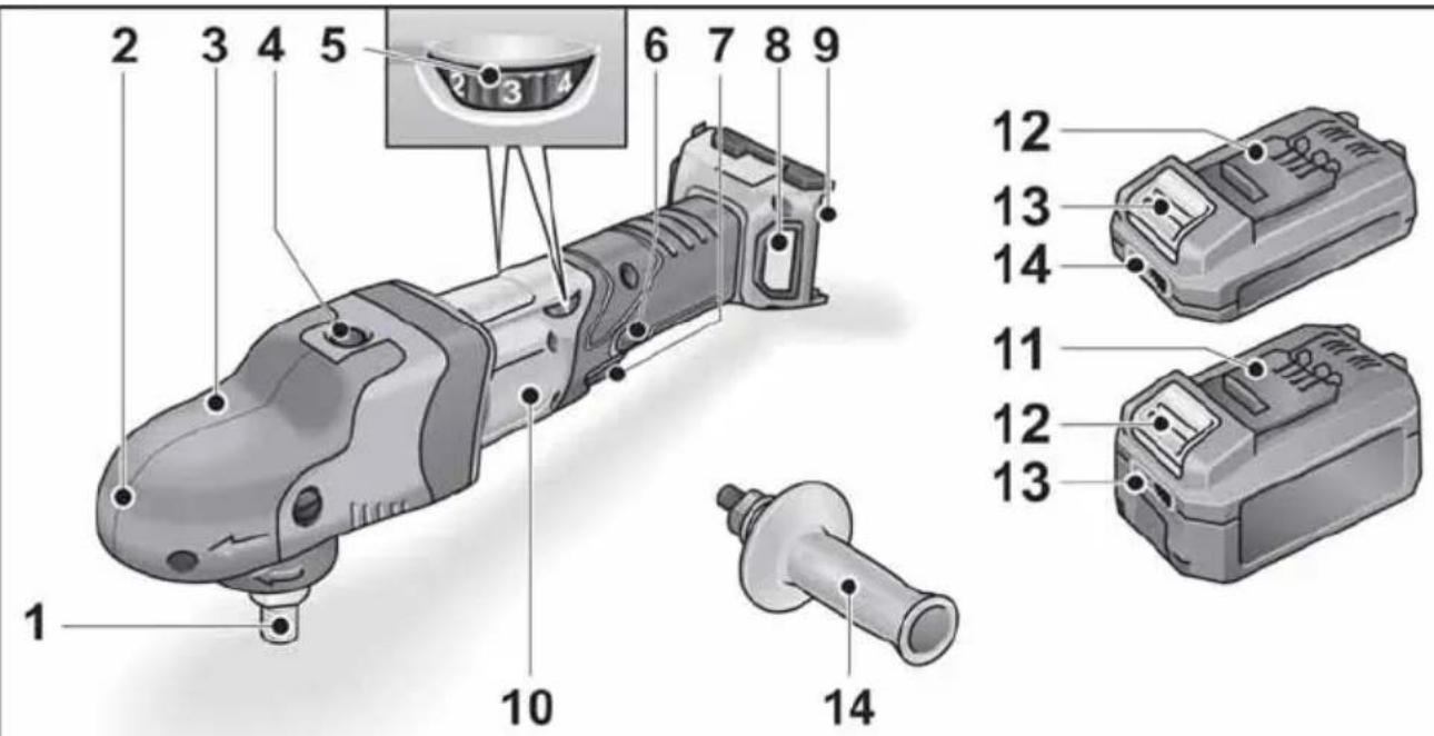
Overview
text_image
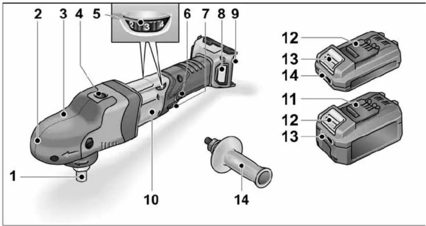
1 2 3 4 5 6 7 8 9 10 12 13 14 11 12 13 141 Spindle
2 Gear head with handle cover
With air outlet and direction-of-rotation arrow.
3 Fastening screw for handle cover
4 Spindle lock
Secures the spindle when the tool is changed.
5 Dial for preselecting the speed
6 Locking button
Locks the switch (7) during continuous operation.
7 S w i t c h
Switches the power tool on and off and also accelerates it up to the preselected speed.
8 Filter cover
9 Slot for battery
10 Rating plate
11 Li-ion battery (2.5 Ah or 5.0 Ah)
12 Release button for battery
13 State of charge indicator
14 Handle
Operating instructions

WARNING!
Remove the battery before carrying out any work on the power tool.
Before switching on the power tool
Unpack the polisher and check that there are no missing or damaged parts.

NOTE
The batteries are not fully charged on delivery. Prior to initial operation, charge the batteries fully. Refer to the charger operating manual.
Attaching the auxiliary handle
The auxiliary handle can be attached to improve handling of the polisher.
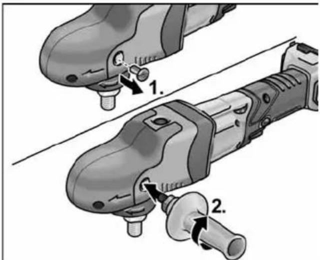
text_image
Diagram showing two mechanical components with labeled parts, likely illustrating a tool or assembly process.To do this, remove the handle cover fastening screw from the side on which the handle is to be attached.
When removing the handle, put back the screw which was removed beforehand.
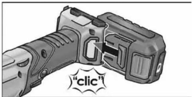
Inserting/replacing the battery
■ Press the charged battery into the power tool until it clicks into place.
natural_image
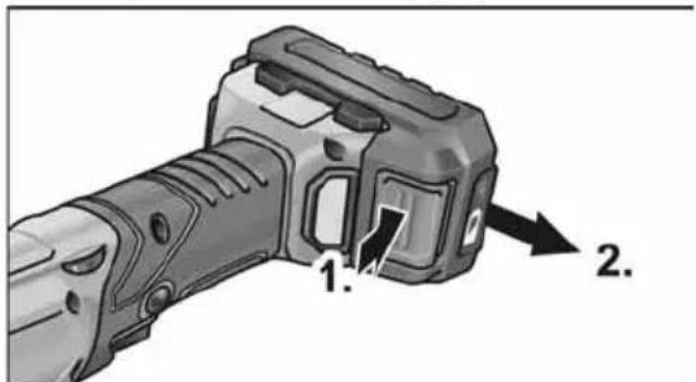
Illustration of a handgun with a button, labeled "clic" (no other text or symbols)■ To remove, press the release button (1.) and pull out the battery (2.).
text_image
1. 2.
CAUTION!
When the device is not in use, protect the battery contacts. Loose metal parts may short-circuit the contacts; explosion and fire hazard!
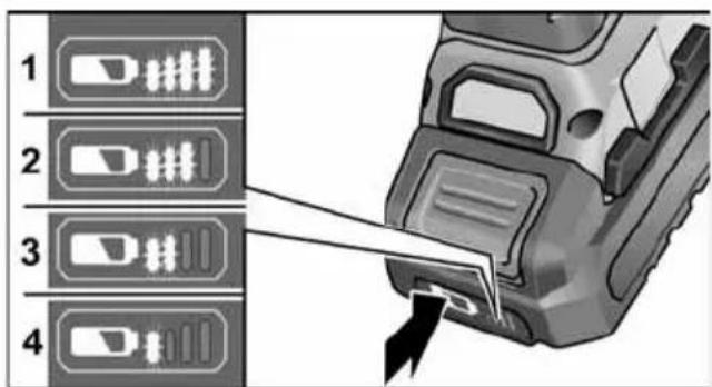
Battery state of charge
■ Press the button to check the state of charge at the state of charge indicator LEDs.
text_image
1 2 3 4The indicator goes out after 5 seconds. If one of the LEDs flashes, the battery must be recharged. If none of the LEDs light up after the button is pressed, the battery is faulty and must be replaced.
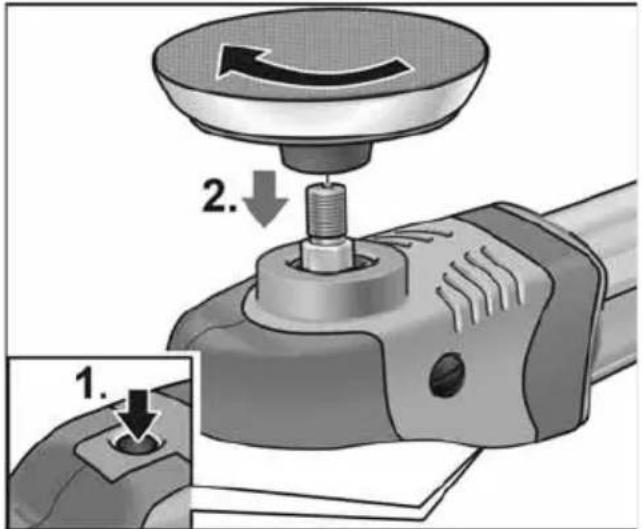
Attaching tool holder
■ Remove the battery.
■ Press and hold down the spindle lock (1.)
text_image
1. 2.■ Screw tool holder (Velcro plate) in clockwise direction onto spindle and tighten by hand (2.).
■ Secure tool on tool holder.
■ Insert the battery.
■ Switch on the polisher (without engaging it) and run the polisher for approx. 30 seconds. Check for imbalances and vibrations.
■ Switch off the polisher.
Changing tool holder
■ Remove the battery.
■ Press and hold down the spindle lock.
■ Unscrew tool holder in anti-clockwise direction and remove it from the spindle by turning.
■ Secure new tool holder (see above).
■ Insert the battery.
Attaching the tools
CAUTION!
Attach tools centrally on tool holder. Imbalances may damage the power tool. The work result may be impaired.
i NOTE
Use original FLEX accessories on this model. Not using original FLEX accessories may lead to a poor polishing result, increased vibrations and also greater wear or even damage to the power tool.
Information concerning foam wear
i NOTE
In general, foam wear is much higher in connection with free-wheeling eccentric polishing that with rotational polishing or force-driven eccentric polishing.
Due to the drive, this wear does not take place on the outside of the foam but at the foam core instead. The harder/longer the cell structure is subjected to strain and damaged as a result, the faster the build-up of heat. Subsequent damage is inevitable. Wear of this kind cannot be seen on the foam externally. The only reliable action is replacement and disposal in good time to prevent thermal damage to the power tool.
Switching on and off
Brief operation without engaged switch rocker
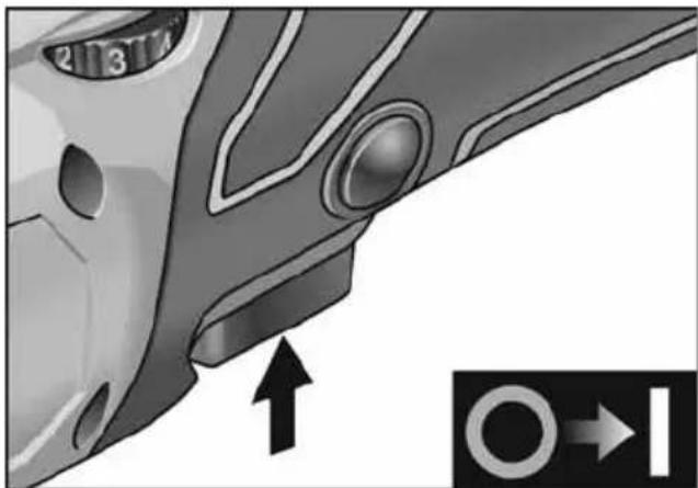
natural_image
Close-up of a car's side profile with a circular component and directional arrow (no text or symbols)■ Press and hold down the switch.
■ To switch off, release the switch.
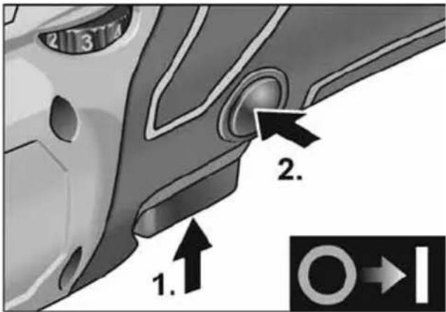
Continuous operation with engaged switch rocker
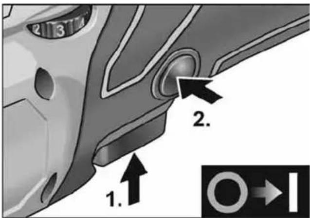
text_image
1. 2. 2.■ Press and hold down switch (1.).
■ To lock into position, hold down the locking button and release the switch (2.).
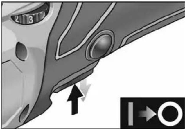
natural_image
Close-up of a car's side profile with no visible text or symbols■ To switch off, briefly press and release the switch.
Preselecting the speed
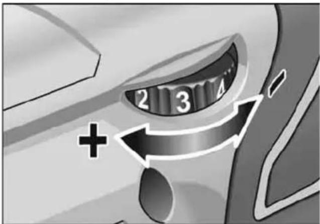
text_image
2 3 +■ To set the operating speed, move the dial to the required value.
■ Gently press the switch to accelerate the power tool up to the preselected speed.
CAUTION!
Risk of injury due to destruction of the tool. Use the appropriate tool for the job.
i NOTE
In the event of overload or overheating in non-stop operation, the power tool will switch off.
To continue working, switch the power tool off and back on again.
Operating instructions
NOTE
When the power tool is switched off, the tool continues running briefly.
If using a polishing paste, use the respective tool for each paste.
Sponges can be washed in the washing machine.
For further information on the manufacturer's products go to www.flex-tools.com.
Charger
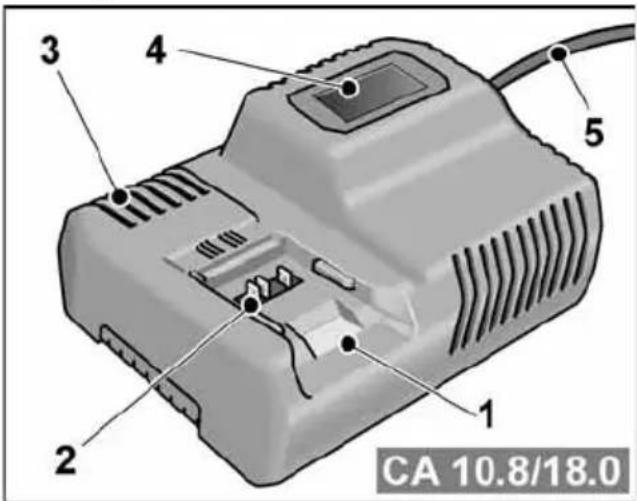
text_image
CA 10.8/18.01 Insertion slot for battery
2 Contacts
3 Ventilation slots
4 Operating state display
5 Power cord with mains plug
The CA 10.8/18.0 charger is designed to charge FLEX batteries of the following types
- AP 10.8 (2.5 Ah),
- AP 18.0 (2.5 Ah),
- AP 10.8 (5.0 Ah),
- AP 18.0 (5.0 Ah).
Tips for a long battery service life

CAUTION!
- Never charge batteries at temperatures below 0 °C or above 55 °C.
- Do not charge batteries in environments with high air humidity or ambient temperature
- Do not cover batteries and the charger during the charging process.
– Pull out the charger mains plug at the end of the charging process.
Battery and charger heat up during the charging process. This is perfectly normal!
Lithium-ion batteries do not exhibit the established "memory effect". Nevertheless, a battery should be completely discharged before charging and the charging process should always be fully completed.
If batteries are not used for an extended period of time, store them partially charged in a cool place.
Charging process

CAUTION!
Insert only original batteries in the supplied charger.
■ Insert the charger mains plug. The display backlighting lights up green for 2 seconds and then goes out again. OK is displayed.
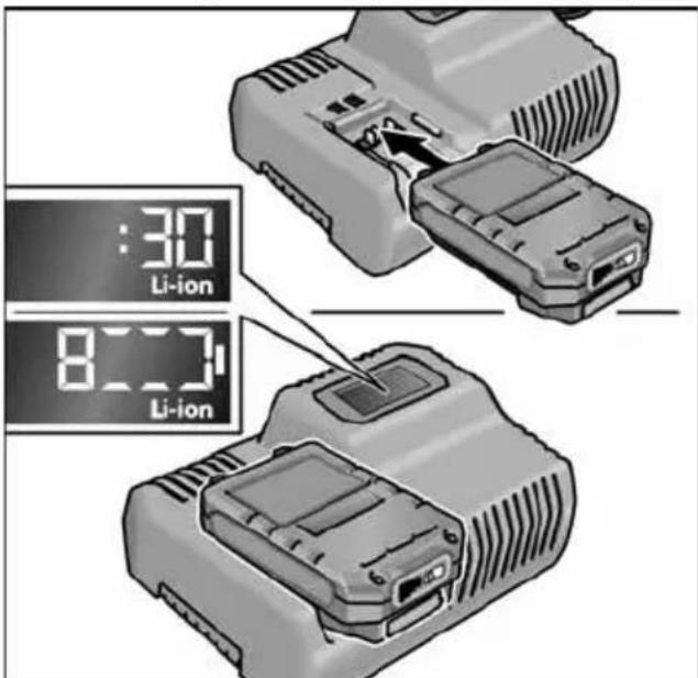
text_image
:30 Li-ion 8:31 Li-ion■ Insert the battery fully into the charger until it clicks into place.
- The time remaining in the charging process (until the battery is fully charged) and a graphic representation of the state of charge are shown alternately in the display.
- The display backlighting lights up orange when the battery is charged less than 80%.
- When the battery charge reaches 80% the display lights up green and OK is indicated.
■ The battery is fully charged when the display appears.

The green backlighting goes out after a short time.
■ Remove the battery from the charger.
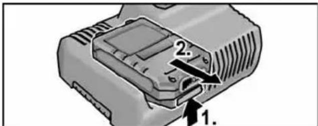
text_image
Diagram of a device component with numbered labels pointing to ports or parts, likely for assembly or labeling.■ Pull out the mains plug.

NOTE
If the display flashes after the battery is inserted in the charger, there is a fault in the battery or in the charger.
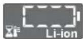
Display flashes slowly. Backlighting orange.
The battery is too hot or too cold. The charging process starts when the battery reaches the charging temperature ( 0^ ...55°C).

Display flashes rapidly. Backlighting red.
Remove the battery from the charger and insert again. If the same display persists, the battery is faulty. Replace the battery or have it checked at an authorised repair shop.
If this error message is displayed again with a different battery, this indicates that there is a fault in the charger. Have the charger checked at an authorised repair shop.
Maintenance and care

WARNING!
Remove the battery before carrying out any work on the power tool.
Cleaning
■ Clean the power tool and grille in front of the vent slots regularly. Frequency of cleaning is dependent on the material and duration of use.
■ Regularly blow out the housing interior and motor with dry compressed air.
■ Regularly clean the filter cover.
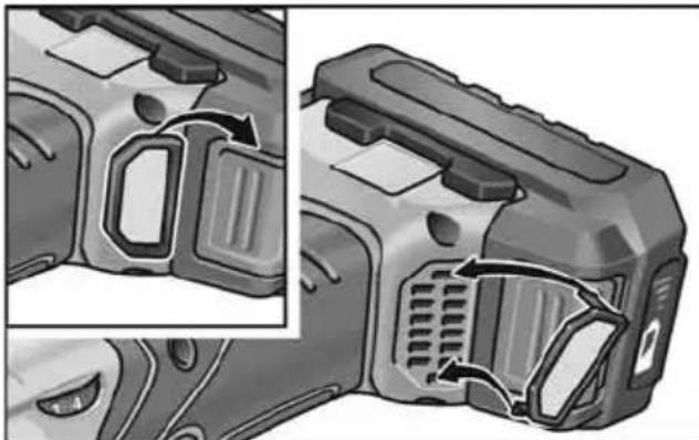
natural_image
Close-up of a mechanical component with internal cutouts and mounting holes, shown from two angles (no text or symbols visible)Remove filter cover and blow it out with dry compressed air.
Gears

NOTE
Do not completely remove the handle cover during the warranty period. Non-compliance will deem the guarantee obligations of the manufacturer null and void.
Repairs
Repairs may be carried out by an authorised customer service centre only.
Spare parts and accessories
For other accessories, in particular tools and polishing aids, see the manufacturer's catalogues. Exploded drawings and spare-part lists can be found on our homepage: www.flex-tools.com
Disposal information

WARNING!
Render redundant power tools unusable:
- mains operated power tool by removing the power cord,
- battery operated power tool by removing the battery.

EU countries only
Do not throw electric power tools into the household waste! In accordance with the European
Directive 2012/19/EU on Waste Electrical and Electronic Equipment and transposition into national law used electric power tools must be collected separately and recycled in an environmentally friendly manner.

Raw material recovery instead of waste disposal.
Device, accessories and packaging should be recycled in an environmentally friendly manner. Plastic parts are identified for recycling according to material type.

WARNING!
Do not throw batteries into the household waste, fire or water. Do not open used batteries.
EU countries only:
In accordance with Directive 2006/66/EC defective or used batteries must be recycled.

NOTE
Please ask your dealer about disposal options!
CE Declaration of Conformity
We declare under our sole responsibility that the product described under “Technical specifications” conforms to the following standards or normative documents:
EN 60745-2-3 in accordance with the regulations of the directives 2014/30/EU, 2006/42/EC, 2011/65/EU.
Responsible for technical documents: FLEX-Elektrowerkzeuge GmbH, R & D Bahnhofstrasse 15, D-71711 Steinheim/Murr

text_image
i.v. P.Caudi B.S.A.R.Peter Lameli Technical Head
Klaus Peter Weinper Head of Quality Department (QD)
15.12.2020
Declaration of Conformity
We as the manufacturer: FLEX
declare under our sole responsibility, that the product(s) described under „Technical specifications“ fulfills all the relevant provisions of The Supply of Machinery (Safety) Regulations S.I. 2008/1597 and also fulfills all the relevant provisions of the following UK Regulations:
Electromagnetic Compatibility Regulations S.I. 2016/1091, The Restriction of the Use of Certain Hazardous Substances in Electrical and Electronic Equipment Regulations S.I. 2012/3032 and are manufactured in accordance with the following designated Standards: BS EN 60745-1:2010, BS EN 60745-2-3:2011, BS EN 55014-1:2017, BS EN 55014-2:2015
Place of declaration: Steinheim, Germany. Responsible person: Peter Lameli, Technical Director – FLEX-Elektrowerk- zeuge GmbH
Contact details for Great Britain:
FLEX Power Tools Limited,
Unit 8 Anglo Office Park, Lincoln Road, HP 12, 3RH Buckinghamshire, United Kingdom

text_image
i.v. P.Caudé B. B. B. B.Peter Lameli Technical Head
Klaus Peter Weinper Head of Quality Department (QD)
19.05.2021
Exemption from liability
The manufacturer and his representative are not liable for any damage and lost profit due to interruption in business caused by the product or by an unusable product. The manufacturer and his representative are not liable for any damage which was caused by improper use of the power tool or by use of the power tool with products from other manufacturers.
Table des matières
text_image
Technical diagram showing two mechanical components with numbered callouts indicating step-by-step assembly or installation.natural_image
Close-up of a car's side profile with circular components and directional arrows (no text or symbols)natural_image
Close-up of a car's side profile with circular components and directional arrow (no text or symbols)text_image
CA 10.8/18.0- AP 10.8 (2,5 Ah),
- AP 18.0 (2,5 Ah),
- AP 10.8 (5,0 Ah),
- AP 18.0 (5,0 Ah).
text_image
Diagram of a device component with numbered labels pointing to ports 1 and 2natural_image
Two views of a device showing internal components with arrows indicating motion or flow (no text or symbols present)Peter Lameli Technical Head

text_image
Bolks Q - 1Klaus Peter Weinper Head of Quality Department (QD)
15.12.2020
text_image
Diagram showing two mechanical components with numbered callouts indicating step-by-step assembly or repair instructions.natural_image
Close-up of a car's side profile with no visible text or symbolsnatural_image
Close-up of a car's side panel with a circular button and directional arrow, no visible text or symbolstext_image
CA 10.8/18.0- AP 10.8 (2,5 Ah),
- AP 18.0 (2,5 Ah),
- AP 10.8 (5,0 Ah),
- AP 18.0 (5,0 Ah).
natural_image
Two views of a firearm component showing internal structure and airflow direction (no text or symbols)Peter Lameli Technical Head

text_image
Bolks -1Klaus Peter Weinper Head of Quality Department (QD)
15.12.2020
text_image
Diagram showing two mechanical components with numbered callouts indicating step-by-step assembly or repair instructions.natural_image
Illustration of a handgun with a button, labeled "clic" (no other text or symbols)natural_image
Close-up of a car's side profile with circular components and directional arrows (no text or symbols)natural_image
Close-up of a car's side profile with a circular button and directional arrow, no visible text or symbolstext_image
CA 10.8/18.0text_image
Diagram of a device component with numbered labels pointing to ports or parts, likely for assembly or labeling.natural_image
Two views of a camera housing showing internal components and airflow direction (no text or symbols)
Peter Lameli
Technical Head

text_image
Bolks -1Klaus Peter Weinper Head of Quality Department (QD)
15.12.2020
text_image
Technical diagram showing two mechanical components with numbered callouts indicating step-by-step installation or repair.natural_image
Illustration of a handgun with a 'click' button, no text or symbols presentnatural_image
Close-up of a car's side profile with circular components and directional arrows (no text or symbols)natural_image
Close-up of a car's side panel with a circular button and directional arrow, no visible text or symbolstext_image
CA 10.8/18.0- AP 10.8 (2,5 Ah),
- AP 18.0 (2,5 Ah),
- AP 10.8 (5,0 Ah),
- AP 18.0 (5,0 Ah).
natural_image
Technical illustration of a firearm component with internal compartments and ventilation slots (no text or symbols)Peter Lameli Technical Head

text_image
Bolters Q.-1Klaus Peter Weinper Head of Quality Department (QD)
15.12.2020
text_image
Technical diagram showing two mechanical components with numbered callouts indicating step-by-step assembly or installation.natural_image
Illustration of a handgun with a button, labeled "clic" (no other text or symbols)text_image
Diagram showing a mechanical tool with labeled parts and directional arrows, including a zoomed-in detail view.natural_image
Close-up of a car's side profile with a circular arrow pointing to the nose area, no visible text or symbols.natural_image
Close-up of a car's side profile with numbered components and an arrow pointing to a circular symbol (no text or labels)text_image
CA 10.8/18.0- AP 10.8 (2,5 Ah),
- AP 18.0 (2,5 Ah),
- AP 10.8 (5,0 Ah),
- AP 18.0 (5,0 Ah).
text_image
Diagram of a device component with numbered labels pointing to ports or parts, likely for assembly or labeling.natural_image
Close-up of a mechanical component with internal channels and mounting brackets, shown from two different angles (no text or symbols visible)text_image
Technical diagram showing two mechanical components with numbered callouts indicating assembly stepsnatural_image
Close-up of a car's side profile with circular components and directional arrows (no text or symbols)natural_image
Close-up of a car's side profile with a circular vent and directional arrow indicator (no text or symbols)text_image
CA 10.8/18.0- AP 10.8 (2,5 Ah),
- AP 18.0 (2,5 Ah),
- AP 10.8 (5,0 Ah),
- AP 18.0 (5,0 Ah).
Anvisninger for lang akku-levetid

FORSIGTIG!
natural_image
Two views of a device casing showing internal components and airflow direction (no text or symbols)text_image
Technical diagram showing two mechanical components with numbered callouts indicating step-by-step assembly or installation.text_image
Diagram showing a mechanical tool with labeled parts and directional arrows, including a magnified inset view.natural_image
Close-up of a car's side profile with circular components and directional arrows (no text or symbols)natural_image
Close-up of a car's side panel showing a circular component with numbered slots and an arrow pointing to a circular symbol (no text or labels present)text_image
CA 10.8/18.0natural_image
Close-up of a firearm component with internal compartments and ventilation slots, shown from two angles (no text or symbols visible)Peter Lameli Technical Head
Klaus Peter Weinper Head of Quality Department (QD)
text_image
Technical diagram showing two mechanical components with numbered callouts indicating step-by-step assembly or installation.natural_image
Illustration of a handgun with a button, labeled "clic" (no other text or symbols)text_image
Diagram showing a mechanical tool with labeled parts and directional arrows, including a zoomed-in detail view.natural_image
Close-up of a car's side profile with circular components and directional arrows (no text or symbols)natural_image
Close-up of a car's side profile with a circular button and directional arrow indicator (no text or symbols)text_image
CA 10.8/18.01 Plats för batteri
2 Kontakter
3 Ventilationsgaller
natural_image
Two views of a firearm component showing internal structure and airflow direction (no text or symbols)Peter Lameli Technical Head
Klaus Peter Weinper Head of Quality Department (QD)
15.12.2020
text_image
Diagram showing two mechanical components with numbered callouts indicating step-by-step assembly or repair instructions.natural_image
Illustration of a handgun with a button and a 'click' label (no text or symbols on the main subject)natural_image
Close-up of a car's side profile with a circular component and directional arrow, no visible text or symbolsnatural_image
Close-up of a car's side profile with numbered slots and an arrow pointing to a circular component (no text or symbols)text_image
CA 10.8/18.0text_image
Diagram of a device component with numbered parts labeled 1 and 2, showing internal structure and connector details.■ Irrota pistotulppa pistorasiasta.

OHJE
natural_image
Two views of a firearm component showing internal structure and airflow direction (no text or symbols)Peter Lameli Technical Head

text_image
B###s -1Klaus Peter Weinper Head of Quality Department (QD)
15.12.2020
text_image
Diagram showing two mechanical components with numbered callouts indicating step-by-step assembly or repair instructions.natural_image
Illustration of a handgun with a button, labeled "clic" (no other text or symbols)natural_image
Close-up of a car's side profile with a circular component and directional arrow, no visible text or symbolsnatural_image
Close-up of a car's side profile with a circular component and directional arrow indicator (no text or symbols)text_image
CA 10.8/18.01 Υποδοχή μπαταρίας
2 E π α φ ε ζ
3 Σ χ 1 σ μ έ ζ
natural_image
Close-up of a mechanical component with a curved arrow indicating rotation (no text or symbols visible)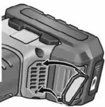
natural_image
Close-up of a mechanical device with internal components and a curved arrow indicating motion (no text or symbols visible)
Peter Lameli
Technical Head

text_image
Bolks Q - 1Klaus Peter Weinper Head of Quality Department (QD)
15.12.2020
text_image
Technical diagram showing two mechanical components with numbered callouts indicating step-by-step assembly or installation.natural_image
Close-up of a car's side profile with a circular component and directional arrow, no visible text or symbolsnatural_image
Close-up of a car's side panel showing a circular component and directional arrow (no text or symbols)text_image
CA 10.8/18.0- AP 10.8 (2,5 Ah),
- AP 18.0 (2,5 Ah),
- AP 10.8 (5,0 Ah),
- AP 18.0 (5,0 Ah).
natural_image
Two views of a firearm component showing internal structure and airflow direction (no text or symbols)Peter Lameli Technical Head
Klaus Peter Weinper Head of Quality Department (QD)
text_image
Technical diagram showing two mechanical components with numbered callouts indicating step-by-step assembly or installation.text_image
Diagram showing a mechanical tool with labeled parts and directional arrows, including a zoomed-in detail view.natural_image
Close-up of a car's side profile with a circular component and directional arrow, no visible text or symbolsnatural_image
Close-up of a car's side panel with a circular vent and directional arrow indicator (no text or symbols)text_image
CA 10.8/18.0- AP 10.8 (2,5 Ah),
- AP 18.0 (2,5 Ah),
- AP 10.8 (5,0 Ah),
- AP 18.0 (5,0 Ah).
natural_image
Close-up of a firearm component with internal air ducts and ventilation slots, shown from two different angles (no text or symbols visible)
Peter Lameli
Technical Head

text_image
Bolters Q.-yKlaus Peter Weinper Head of Quality Department (QD)
15.12.2020
text_image
Diagram showing two mechanical components with numbered callouts indicating step-by-step installation or repair process.natural_image
Close-up of a car's side profile with a circular lens and directional arrow indicator (no text or symbols)natural_image
Close-up of a car's side profile with a circular vent and directional arrow indicator (no text or symbols)text_image
CA 10.8/18.0natural_image
Close-up of a firearm component showing internal air ducts and ventilation slots (no text or symbols visible)Peter Lameli Technical Head
Klaus Peter Weinper Head of Quality Department (QD)
-
- 15
text_image
Diagram showing two mechanical components with numbered callouts indicating step-by-step assembly or repair instructions.natural_image
Illustration of a handgun with a button, labeled "clic" (no other text or symbols)natural_image
Close-up of a car's side profile with a circular component and directional arrow, no visible text or symbolsnatural_image
Close-up of a car's side panel with a circular button and directional arrow indicator (no text or symbols)text_image
CA 10.8/18.0natural_image
Close-up of a mechanical device showing internal components and airflow direction (no text or symbols)text_image
Technical diagram showing two mechanical components with numbered callouts indicating step-by-step assembly or repair.natural_image
Illustration of a handgun with a button, labeled "clic" (no other text or symbols)■ Pri vyberaní stlačte zaist'ovacie tlačidlá (1.) a akumulátor vytiahnite (2.).

text_image
1. 2.
POZOR!
natural_image
Close-up of a car's side profile with a circular component and directional arrow, no visible text or symbolsnatural_image
Close-up of a car's side panel showing a circular component with numbered slots and an arrow pointing to a circular symbol (no text or labels present)text_image
CA 10.8/18.01 Šachta na zasunutie akumulátora
2 Kontakty
3 Vetracie štrbiny
4 Displej na zobrazenie stavu prevádzky
5 Siet'ový kábel so siet'ovou zástrčkou
Nabíjačka CA 10.8/18.0 je určená na nabíjanie akumulátorov FLEX typu
- AP 10.8 (2,5 Ah),
- AP 18.0 (2,5 Ah),
- AP 10.8 (5,0 Ah),
- AP 18.0 (5,0 Ah).
natural_image
Technical illustration of a mechanical device with internal components and highlighted parts (no text or symbols)text_image
Technical diagram showing two mechanical components with numbered callouts indicating step-by-step assembly or installation.natural_image
Close-up of a car's side profile with a circular button and directional arrow indicator (no text or symbols)natural_image
Close-up of a car's side panel with circular components and an arrow pointing to a circular symbol (no text or labels)text_image
CA 10.8/18.01 Otvor za umetanje akumulatora
2 Kontakti
3 Prorezi za ventilaciju
4 Zaslon za prikaz radnog stanja
5 Mrežni kabel s mrežnim utikačem
Punjač CA 10.8/18.0 namijenjen je za punjenje FLEX akumulatora tipa
- AP 10.8 (2,5 Ah),
- AP 18.0 (2,5 Ah),
- AP 10.8 (5,0 Ah),
- AP 18.0 (5,0 Ah).
natural_image
Two views of a firearm component showing internal compartments and ventilation slots (no text or symbols visible)Izvadite filtar za prašinu i ispušite suhim komprimiranim zrakom.
Prijenosnik

NAPUTAK!
Peter Lameli Technical Head
Klaus Peter Weinper Head of Quality Department (QD)
15.12.2020
Hrup in tresljaji 211
text_image
Technical diagram showing two mechanical components with numbered callouts indicating step-by-step assembly or installation.natural_image
Illustration of a handgun with a 'click' button and a starburst symbol (no text or symbols on the main subject)natural_image
Close-up of a car's side profile with a circular component and directional arrows indicating movement (no text or symbols)■ Pritisnite in pridržite stikalo.
■ Za izklop sprostite stikalo.
Trajno delovanje z zaklepom
text_image
1. 2. 2.■ Pritisnite in pridržite stikalo (1.).
■ Za zaklep položaja pridržite gumb za zaklep (2.) in sprostite stikalo.

natural_image
Close-up of a car's side profile with a circular button and directional arrow indicator (no text or symbols)■ Za izklop stikalo na kratko pritisnite in ga nato izpustite.
text_image
CA 10.8/18.01 Reža za vstavljanje akumulatorske baterije
- AP 10.8 (2,5 Ah),
- AP 18.0 (2,5 Ah),
- AP 10.8 (5,0 Ah),
- AP 18.0 (5,0 Ah).
natural_image
Two views of a device showing internal components with arrows indicating motion or flow (no text or symbols present)Snemite filter za prah in ga izpihajte s suhim stisnjenim zrakom.
Gonilo

OPOMBA
text_image
Diagram showing two mechanical components with numbered callouts indicating step-by-step installation or repair process.natural_image
Close-up of a car's side profile with a circular component and directional arrow, no visible text or symbolsnatural_image
Close-up of a car's side panel showing the nose and eye area with an arrow pointing to a circular symbol (no text or labels)text_image
CA 10.8/18.0- AP 10.8 (2,5 Ah),
- AP 18.0 (2,5 Ah),
- AP 10.8 (5,0 Ah),
- AP 18.0 (5,0 Ah).
natural_image
Close-up of a firearm component with internal compartments and ventilation slots, shown from two different angles (no text or symbols visible)EN 60745-2-3 conform prevederilor Directivei 2014/30/UE, 2006/42/CE, 2011/65/UE.
Responsabili pentru documente tehnice: FLEX-Elektrowerkzeuge GmbH, R & D Bahnhofstrasse 15, D-71711 Steinheim/Murr

text_image
i.v. P.Claud Peter Lameli Technical Head Klaus Peter Weinper Head of Quality Department (QD)15.12.2020
text_image
Diagram showing two mechanical components with numbered callouts indicating step-by-step assembly or repair instructions.natural_image
Close-up of a car's side profile with a circular component and directional arrow indicator (no text or symbols)natural_image
Close-up of a car's side panel showing a circular component with numbered slots and an arrow pointing to a circular symbol (no text or labels present)text_image
CA 10.8/18.0natural_image
Two views of a device showing internal components with arrows indicating motion or flow (no text or symbols present)Peter Lameli
Technical Head
Klaus Peter Weinper
Head of Quality
Department (QD)
15.12.2020
text_image
Technical diagram showing two mechanical components with numbered callouts indicating step-by-step assembly or installation.natural_image
Close-up of a car's side profile with circular components and directional arrows (no text or symbols)natural_image
Close-up of a car's side panel with a circular vent and directional arrow indicator (no text or symbols)text_image
CA 10.8/18.0- AP 10.8 (2,5 A*4),
- AP 18.0 (2,5 A*4),
- AP 10.8 (5,0 A*4),
- AP 18.0 (5,0 A*4).
natural_image
Close-up of a firearm component with internal compartments and ventilation slots, shown from two different angles (no text or symbols visible)Klaus Peter Weinper Head of Quality Department (QD)
15.12.2020
text_image
Technical diagram showing two mechanical components with numbered callouts indicating step-by-step assembly or installation.text_image
Diagram showing a mechanical tool with labeled parts and directional arrows, including a zoomed-in detail view.natural_image
Close-up of a car's side profile with a circular lens and directional arrow indicator (no text or symbols)natural_image
Close-up of a car's side profile with a circular button and directional arrow, no visible text or symbolstext_image
CA 10.8/18.01 Aku pesa
2 K o n t a k t i d
- AP 10.8 (2,5 Ah),
- AP 18.0 (2,5 Ah),
- AP 10.8 (5,0 Ah),
- AP 18.0 (5,0 Ah).
text_image
Diagram of a device component with numbered parts labeled 1 and 2, showing internal structure and mounting points.natural_image
Two views of a mechanical component with internal channels and mounting brackets, shown from different angles (no text or symbols visible)text_image
Technical diagram showing two mechanical components with numbered callouts indicating step-by-step assembly or installation.natural_image
Close-up of a car's side profile with a circular component and directional arrow indicator (no text or symbols)natural_image
Close-up of a car's side profile with circular components and directional arrow (no text or symbols)text_image
CA 10.8/18.0- AP 10.8 (2,5 Ah),
- AP 18.0 (2,5 Ah),
- AP 10.8 (5,0 Ah),
- AP 18.0 (5,0 Ah).
natural_image
Close-up of a mechanical component with internal channels and mounting holes, shown from two different angles (no text or symbols visible)text_image
Technical diagram showing two mechanical components with numbered callouts indicating step-by-step assembly or installation.Dim nolûkam izskrûvçjiet nostiprinâjuma skrûvi roktura apvalka malâ, pie kuras nepiecieðama roktura montâba.
Rokturi demontcjot, no jauna piemontcjiet iepriekõ izskrûvçto skrûvi.
natural_image
Illustration of a handgun with a button and a 'click' label (no text or symbols on the main subject)■ Lai akumulatoru iznemtu, nospiediet atblokēšanas taustinu (1.) un iznemiet akumulatoru (2.).

text_image
1. 2.
UZMANĪBU!
text_image
Diagram showing a mechanical tool with labeled parts and directional arrows, including a zoomed-in detail view.natural_image
Close-up of a car's side profile with a circular lens and directional arrow indicator (no text or symbols)natural_image
Close-up of a car's side panel with a circular vent and directional arrow indicator (no text or symbols)text_image
CA 10.8/18.0text_image
Diagram of a device component with numbered parts labeled 1 and 2, showing internal structure and connector details.■ Atvienojiet spraudni.

NORĀDĪJUMS!
natural_image
Two views of a firearm component showing internal structure and airflow direction (no text or symbols)Nonemiet puteklu filtru un izpūtiet to ar sausu saspiesto gaisu.
Pārvads

NORĀDĪJUMS!
Peter Lameli Technical Head

text_image
Handwritten signature or scribble with partial text and a curved line, likely from a document or form.Klaus Peter Weinper
Head of Quality Department (QD)
2020/12/15
natural_image
Close-up of a mechanical component with no visible text or symbols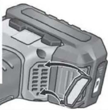
natural_image
Close-up of a mechanical device with visible internal components and a curved arrow indicating motion (no text or symbols).80% ي Had Shun the Bpatarine Aqll m
text_image
CA 10.8/18.0natural_image
Close-up of a car's side panel showing a circular component and a directional arrow (no text or symbols)natural_image
Close-up of a car's side profile with a circular eye and directional arrows indicating movement (no text or symbols)text_image
Technical diagram showing two mechanical components with labeled parts, likely illustrating a tool or assembly process.natural_image
Illustration of a handgun with a button labeled 'G' and a speech bubble containing the word 'clic' (no other text or symbols)