
LBE 20-10 150-EC - Grinder Flex - Free user manual and instructions
Find the device manual for free LBE 20-10 150-EC Flex in PDF.

| Product type | Angle grinder |
| Brand | Flex |
| Model | LBE 20-10 150-EC |
| Rated voltage | 220-240 V~ |
| Frequency | 50/60 Hz |
| Input power | 2000 W |
| No-load speed | 0-10000 rpm |
| Max. disc diameter | 150 mm |
| Spindle thread | M14 |
| Weight (according to EPTA 01/2003) | 2.86 kg |
| Acoustic pressure level LpA | 89.97 dB(A) |
| Vibration value (surface grinding) | 7.35 m/s² |
| Switch type | Rocker switch (continuous operation possible) |
| Electronic speed control | Yes, 6 levels |
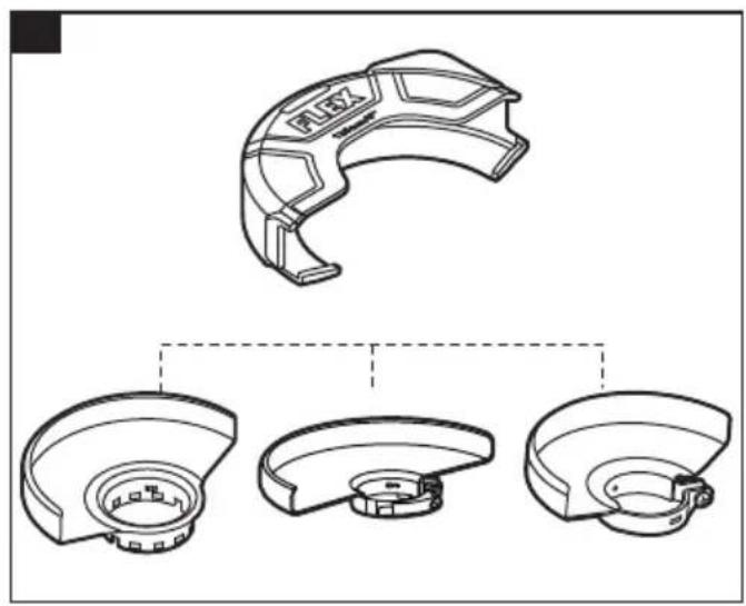
| Protective guard supplied | Grinding guard and cutting guard (clip included) |
| Auxiliary handle | Yes, left or right mounting |
| Spindle lock | Yes |
| Dust filter | Yes (removable filter cover) |
| Protection class | II (double insulation) |
| Operating temperature | -10 °C to +40 °C |
| Storage temperature | -40 °C to +70 °C |
Frequently Asked Questions - LBE 20-10 150-EC Flex
User questions about LBE 20-10 150-EC Flex
0 question about this device. Answer the ones you know or ask your own.
Ask a new question about this device
Download the instructions for your Grinder in PDF format for free! Find your manual LBE 20-10 150-EC - Flex and take your electronic device back in hand. On this page are published all the documents necessary for the use of your device. LBE 20-10 150-EC by Flex.
USER MANUAL LBE 20-10 150-EC Flex
natural_image
Line drawings of three FLEX industrial machines with no visible text or symbols

en Original operating instructions....19
natural_image
Line drawing of a wrench with a labeled measurement of 15 (no text or symbols on the tool itself)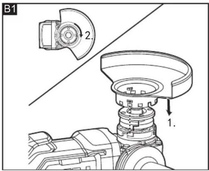
natural_image
Technical line drawing of a mechanical component with three views (top, front, side), no text or symbols present.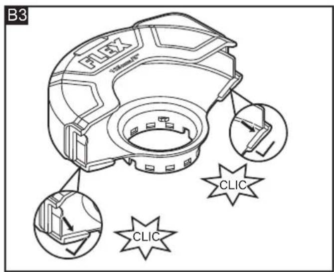
natural_image
Technical line drawing of a mechanical component with internal channels and a directional arrow (no text or symbols)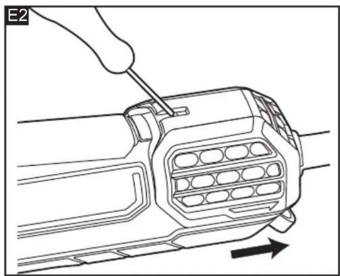
natural_image
Technical line drawing of a mechanical component with a hand using a screwdriver to adjust internal channels (no text or symbols)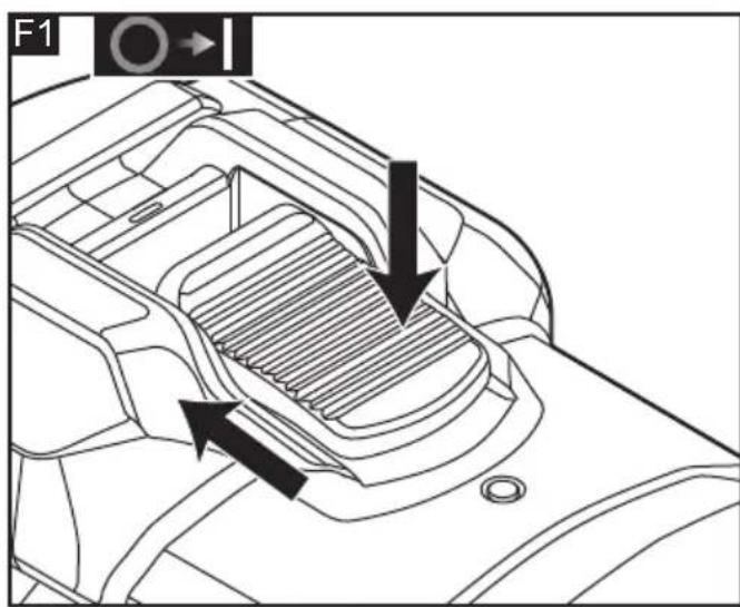
natural_image
Technical diagram of a mechanical component with internal channels and directional arrows indicating movement (no text or symbols)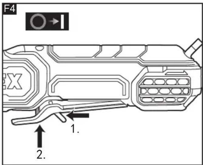
natural_image
Diagram of a device front panel with buttons and a black arrow pointing to the interior (no text or symbols)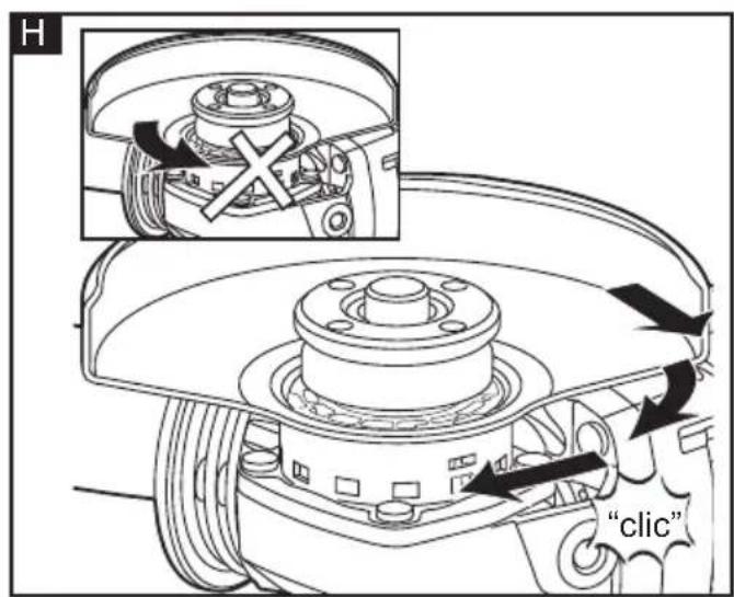
natural_image
Illustration of hands using a FLEX tool to cut the blade (no text or symbols present)Inhalt
EN IEC 62841-2-3:2020+A11:2021
EN IEC 55014-1:2021
EN IEC 55014-2:2021
EN 61000-3-2:2019+A1:2021
EN 61000-3-3:2013+A1:2019
Symbols used in this manual ..... 19
Symbols on the product....19
Important safety information....19
Noise and vibration 23
Technical data....24
Overview....25
Operating instructions 25
Maintenance and care....27
Disposal information....28
CE Declaration of conformity....28
UK CA Declaration of conformity....29
Exemption from liability 29
Symbols used in this manual
WARNING!
Denotes impending danger. Non-observance of this warning may result in death or extremely severe injuries.
CAUTION!
Denotes a possibly dangerous situation. Non-observance of this warning may result in slight injury or damage to property.
NOTE
Denotes application tips and important information.
Symbols on the product

Before switching on the power tool, read the operating manual.

Wear protective goggles.

Always operate with two hands

Do not use the guard for cut-off operations

Protection class II (completely insulated)

Disposal information for the old machine (see page 28)

CE marking

UKCA marking
Important safety information
WARNING!
Before using the power tool, please read the following and act accordingly:
– these operating instructions,
- the "General safety instructions" on the handling of power tools in the enclosed booklet (leaflet-no.: 315915),
- the currently valid site rules and the regulations for the prevention of accidents.
This power tool is state of the art and has been constructed in accordance with the acknowledged safety regulations.
Nevertheless, when in use, the power tool may pose a danger to life and limb of the user or a third party, or the power tool or other property may be damaged.
The power tool my be operated only
- for its intended use
- in perfect working order.
Faults which impair safety must be repaired immediately.
Intended use
- This angle grinder is intended for commercial use.
- It is designed for dry cutting and grinding metal, stone and similar materials, as well as wire brushing and hole cutting in stone material with diamond hole cutter, without the use of water.
- For cutting, a special cutting guard is required (see Pos.14 figure. A).
- Please note that sufficient dust extraction is needed when cutting stone.
- When using diamond grinding wheels for surface grinding of masonry/concrete/ stone, the FLEX diamond surface grinding wheel guard (Type: SG-R D125) must be used.
- Tools must be approved for a speed of at least 11000 /min.
Safety instructions for angle grinder
Safety instructions for all operations Safety warnings common for grinding, sanding, wire brushing or cutting-off operations:
■ This power tool is intended to function as a grinder, sander, wire brush, hole cutter or cut-off tool. Read all safety warnings, instructions, illustrations and specifications provided with this power tool. Failure to follow all instructions listed below may result in electric shock, fire and/or serious injury.
■ Operations such as polishing is not to be performed with this power tool.
Operations for which the power tool was not designed may create a hazard and cause personal injury.
■ Do not convert this power tool to operate in a way which is not specifically designed and specified by the tool manufacturer. Such a conversion may result in a loss of control and cause serious personal injury.
■ Do not use accessories which are not specifically designed and specified by the tool manufacturer. Just because the accessory can be attached to your power tool, it does not assure safe operation.
■ The rated speed of the accessory must be at least equal to the maximum speed marked on the power tool. Accessories running faster than their rated speed can break and fly apart.
■ The outside diameter and the thickness of your accessory must be within the capacity rating of your power tool. Incorrectly sized accessories cannot be adequately guarded or controlled.
■ The dimensions of the accessory mounting must fit the dimensions of the mounting hardware of the power tool. Accessories that do not match the mounting hardware of the power tool will run out of balance, vibrate excessively and may cause loss of control.
- Do not use a damaged accessory. Before each use inspect the accessory such as abrasive wheels for chips and cracks, backing pad for cracks, tear or excess wear, wire brush for loose or cracked wires. If power tool or accessory is dropped, inspect for damage or install an undamaged accessory. After inspecting and installing an accessory, position yourself and bystanders away from the plane of the rotating accessory and run the power tool at maximum no-load speed for one minute. Damaged accessories will normally break apart during this test time.
■ Wear personal protective equipment. Depending on application, use face shield, safety goggles or safety glasses. As appropriate, wear dust mask, hearing protectors, gloves and workshop apron capable of stopping small abrasive or workpiece fragments. The eye protection must be capable of stopping flying debris generated by various applications. The dust mask or respirator must be capable of filtrating particles generated by the particular application. Prolonged exposure to high intensity noise may cause hearing loss.
- Keep bystanders a safe distance away from work area. Anyone entering the work area must wear personal protective equipment. Fragments of workpiece or of a broken accessory may fly away and cause injury beyond immediate area of operation.
- Hold the power tool by insulated gripping surfaces only, when performing an operation where the cutting accessory may contact hidden wiring or its own cord. Cutting accessory contacting a "live" wire may make exposed metal parts of the power tool "live" and could give the operator an electric shock.
■ Position the cord clear of the spinning accessory. If you lose control, the cord may be cut or snagged and your hand or arm may be pulled into the spinning accessory.
■ Never lay the power tool down until the accessory has come to a complete stop. The spinning accessory may grab the surface and pull the power tool out of your control.
■ Do not run the power tool while carrying it at your side. Accidental contact with the spinning accessory could snag your clothing, pulling the accessory into your body.
- Regularly clean the power tool's air vents.
The motor's fan will draw the dust inside the housing and excessive accumulation of powdered metal may cause electrical hazards.
■ Do not operate the power tool near flammable materials. Sparks could ignite these materials.
■ Do not use accessories that require liquid coolants. Using water or other liquid coolants may result in electrocution or shock.
Further safety instructions for all operations
⚠️ Kickback and Related Warnings:
Kickback is a sudden reaction to a pinched or snagged rotating wheel, backing pad, brush or any other accessory. Pinching or snagging causes rapid stalling of the rotating accessory which in turn causes the uncontrolled power tool to be forced in the direction opposite of the accessory's rotation at the point of the binding.
For example, if an abrasive wheel is snagged or pinched by the workpiece, the edge of the wheel that is entering into the pinch point can dig into the surface of the material causing the wheel to climb out or kick out. The wheel may either jump toward or away from the operator, depending on direction of the wheel's movement at the point of pinching. Abrasive wheels may also break under these conditions.
Kickback is the result of power tool misuse and/or incorrect operating procedures or conditions and can be avoided by taking proper precautions as given below.
- Maintain a firm grip with both hands on the power tool and position your body and arm to allow you to resist kickback forces. Always use auxiliary handle, if provided, for maximum control over kickback or torque reaction during start-up. The operator can control torque reactions or kickback forces, if proper precautions are taken.
■ Never place your hand near the rotating accessory. Accessory may kickback over
your hand.
- Do not position your body in the area where power tool will move if kickback occurs. Kickback will propel the tool in direction opposite to the wheel's movement at the point of snagging.
■ Use special care when working corners, sharp edges etc. Avoid bouncing and snagging the accessory. Corners, sharp edges or bouncing have a tendency to snag the rotating accessory and cause loss of control or kickback. - Do not attach a saw chain woodcarving blade, segmented diamond wheel with a peripheral gap greater than 10 mm or toothed saw blade. Such blades create frequent kickback and loss of control.
Additional safety instructions for grinding and cutting-off operations
Safety warnings specific for grinding and cutting-off operations:
■ Use only wheel types that are specified for your power tool and the specific guard designed for the selected wheel.
Wheels for which the power tool was not designed cannot be adequately guarded and are unsafe.
■ The grinding surface of center depressed wheels must be mounted below the plane of the guard lip. An improperly mounted wheel that projects through the plane of the guard lip cannot be adequately protected.
■ The guard must be securely attached to the power tool and positioned for maximum safety, so the least amount of wheel is exposed towards the operator.
The guard helps to protect the operator from broken wheel fragments, accidental contact with wheel and sparks that could ignite clothing.
- Wheels must be used only for specified applications. For example: do not grind with the side of cut-off wheel. Abrasive cut-off wheels are intended for peripheral grinding, side forces applied to these wheels may cause them to shatter.
■ Always use undamaged wheel flanges that are of correct size and shape for your selected wheel. Proper wheel flanges support the wheel thus reducing the
possibility of wheel breakage. Flanges for cut-off wheels may be different from grinding wheel flanges.
- Do not use worn down wheels from larger power tools. A wheel intended for larger power tool is not suitable for the higher speed of a smaller tool and may burst.
- When using dual purpose wheels always use the correct guard for the application being performed. Failure to use the correct guard may not provide the desired level of guarding, which could lead to serious injury.
Additional safety instructions for cutting-off operations
Additional safety warnings specific for cutting-off operations:
- Do not "jam" the cut-off wheel or apply excessive pressure. Do not attempt to make an excessive depth of cut.
Overstressing the wheel increases the loading and susceptibility to twisting or binding of the wheel in the cut and the possibility of kickback or wheel breakage.
■ Do not position your body in line with and behind the rotating wheel. When the wheel, at the point of operation, is moving away from your body, the possible kickback may propel the spinning wheel and the power tool directly at you.
- When the wheel is binding or when interrupting a cut for any reason, switch off the power tool and hold it motionless until the wheel comes to a complete stop. Never attempt to remove the cut-off wheel from the cut while the wheel is in motion otherwise kickback may occur. Investigate and take corrective action to eliminate the cause of wheel binding.
- Do not restart the cutting operation in the workpiece. Let the wheel reach full speed and carefully re-enter the cut. The wheel may bind, walk up or kickback if the power tool is restarted in the workpiece.
■ Support panels or any oversized workpiece to minimize the risk of wheel pinching and kickback. Large workpieces tend to sag under their own weight. Supports must be placed under the workpiece near the line of cut and near the edge of the workpiece on both sides
of the wheel.
■ Use extra caution when making a "pocket cut" into existing walls or other blind areas. The protruding wheel may cut gas or water pipes, electrical wiring or objects that can cause kickback.
■ Do not attempt to do curved cutting. Overstressing the wheel increases the loading and susceptibility to twisting or binding of the wheel in the cut and the possibility of kickback or wheel breakage, which can lead to serious injury.
Safety warnings specific for sanding operations:
■ Use proper sized sanding disc paper. Follow manufacturers recommendations, when selecting sanding paper. Larger sanding paper extending too far beyond the sanding pad presents a laceration hazard and may cause snagging, tearing of the disc or kickback.
Safety warnings specific for wire brushing operations:
■ Be aware that wire bristles are thrown by the brush even during ordinary operation. Do not overstress the wires by applying excessive load to the brush. The wire bristles can easily penetrate light clothing and/or skin.
■ If the use of a guard is specified for wire brushing, do not allow any interference of the wire wheel or brush with the guard. Wire wheel or brush may expand in diameter due to work load and centrifugal forces.
Additional safety instructions
- The mains voltage and the voltage specifications on the rating plate must correspond.
- Do not press the spindle lock until the grinding tool stops.
- Threaded mounting of accessories must match the grinder spindle thread. For accessories mounted by flanges, the arbour hole of the accessory must fit the locating diameter of the flange. Accessories that do not match the mounting hardware of the power tool will run out of balance, vibrate excessively and may cause loss of control.
- When sanding with sandpaper, high surface temperatures can occur, please adjust the speed accordingly.
Noise and vibration
NOTE
Values for the A-weighted sound pressure level and for the total vibration values can be found in the "Technical data" table.
The noise and vibration values have been determined in accordance with EN 62841.
CAUTION!
The indicated measurements refer to new power tools. Daily use causes the noise and vibration values to change.
NOTE
The vibration emission level given in this information sheet has been measured in accordance with a standardised test given in EN 62841 and may be used to compare one tool with another. It may be used for a preliminary assessment of exposure. The declared vibration emission level represents the main applications of the tool. However if the tool is used for different applications, with different accessories or poorly maintained, the vibration emission may differ. This may significantly increase the exposure level over the total working period.
Identify additional safety measures to protect the operator from the effects of vibration such as: maintain the tool and the accessories, keep the hands warm, organisation of work patterns.
CAUTION!
Wear ear protection at a sound pressure above 85 dB(A).
Technical data
| Product type LB 20-11 | 125-EC | LBP 20-11125-EC | LBE 20-11125-EC | LBE 20-10150-EC | LBE 20-8125-ECINOX | |||
| Product Angle Grinder | ||||||||
| Rated voltage V 22 | 0-240 | |||||||
| Frequency Hz 50/60 | ||||||||
| Safety class II | ||||||||
| Input power W 2000 | ||||||||
| No load speed /min | 11000 | 1000 3000 | -11000 300 | 0-10000 300 | 0-7800 | |||
| Wheel type | TYPE 27 & TYPE 28& TYPE 29 | |||||||
| Wheel diameter | mm | Φ125 | Φ125 | Φ125 | Φ150 | Φ125 | ||
| Wheel thickness | mm | Max. 6mm | ||||||
| Spindle thread | M14 | |||||||
| Weight according to"EPTA Procedure 01/2003" | kg | 2.76kg | 2.81kg | 2.76kg | 2.86kg | 2.76kg | ||
| A-weighted sound pressure level according to EN 62841 | ||||||||
| Sound pressure level L_pA | dB(A) | 92.37 | 92.37 | 92.37 | 89.97 | 85.90 | ||
| Sound power level L_WA | dB(A) | 100.37 | 100.37 | 100.37 | 97.97 | 93.90 | ||
| Uncertainty K | db | 3 | ||||||
| Total vibration value accordance with EN 62841 | ||||||||
| Emission value a_h when grinding surfaces | m/s^2 | 6.61 | 7.07 | 6.61 | 7.35 | 5.87 | ||
| Uncertainty K | m/s^2 | 1.5 | ||||||
| Working Temperature | -10 - 40°C | |||||||
| Storage Temperature | -40 - 70°C | |||||||
Overview (Figure A)
The numbering of the product features refers to the illustration of the machine on the graphics page.
1. Switch rocker
(For LB 20-11 125-EC, LBE 20-11 125-EC, LBE 20-10 150-EC, LBE 20-8 125-EC INOX)
2. Rear handle
3. Speed control button
(For LBE 20-11 125-EC, LBE 20-10 150-EC, LBE 20-8 125-EC INOX)
Function with 6 levels
4. Power cord with plug
5. Filter cover
6. Auxiliary handle
Handle can be fitted on the left or the right
7. Protective guard for grinding
8. Threaded flange
a Clamping flange
b Clamping nut
9. Spindle
10. Gear head
11. Spindle lock
Secures the spindle when the tool is changed
12. Paddle switch
(For LBP 20-11 125-EC)
13. Paddle Lock-off lever
(For LBP 20-11 125-EC)
14. Protective clip on guard for cutting
15. Pin wrench
16. Tether mount
(For LBP 20-11 125-EC, tether not included)
Operating instructions
WARNING!
Before performing any work on the electric power tool, pull out the mains plug.
Before switching on the power tool
Unpack the angle grinder and check that there are no missing or damaged parts.
Installing and removing the protective guard (see figure B1-B3)
WARNING!
Never work without the protective guard.
Attempting to use grinder with guard removed will result in serious personal injury.
WARNING!
Always use protective guard for grinding when grinding!
Always use protective guard for cutting when cutting!
WARNING!
If any parts are damaged or missing do not operate this product until the parts are replaced. Use of this product with damaged or missing parts could result in serious personal injury.
To install the guard
■ Pull out the mains plug.
■ Attach the guard (7). Lugs on the guard hood must be located in the flange recesses.
■ Turn guard (7) hood clockwise to the required position.
Rotation is possible in clockwise direction only!
■ Remove in reverse order.
NOTE
The clip on guard for cutting needs to be used in combination with the protective guard for grinding. Lock the two buckles of the clip on guard for cutting (14) on both sides of the protective guard for grinding (7) installation port and listen for a "CLIC" sound to ensure that it is installed in place (see figure B2-B3).
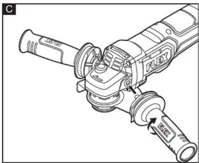
Auxiliary handle (see figure C)

WARNING!
Always be sure that the auxiliary handle is installed securely before operation.
Screw the auxiliary handle (6) securely on the position of the tool as shown in the figure C.
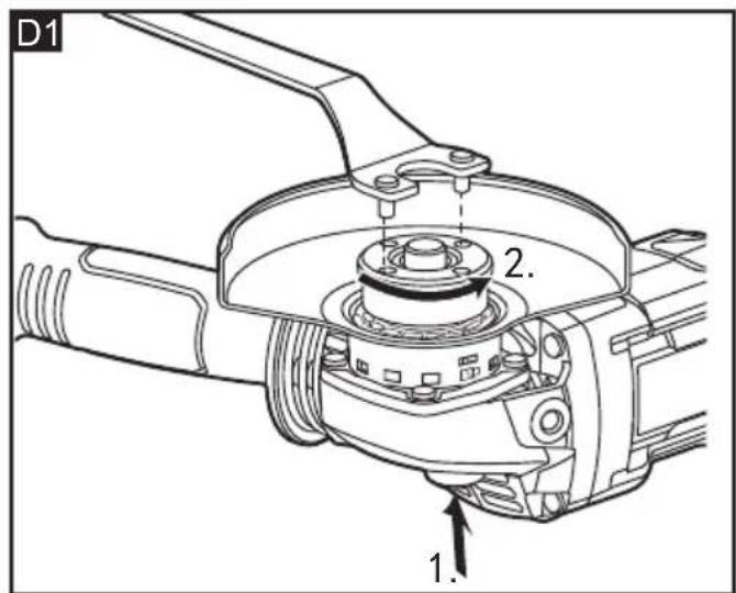
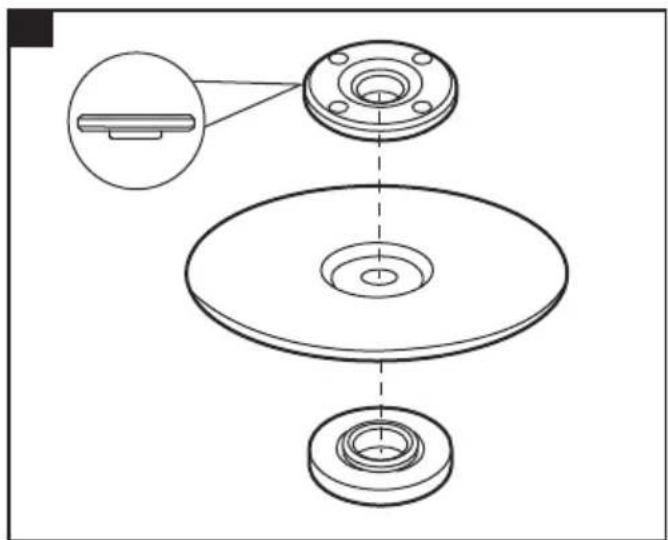
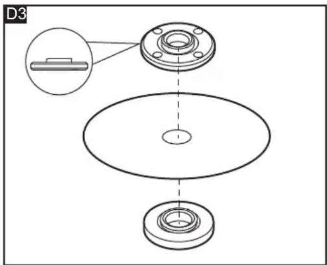
Installing and removing the grinding or cutting wheel (see figure D1-D3)
To install the wheel
■ Pull out the mains plug.
■ Press and hold down the spindle lock (11).
■ Using the pin wrench (15), loosen the clamping nut (8b) on the spindle (9) in an anti-clockwise direction and remove.
■ Insert the wheel in the correct position.
■ Tighten the clamping nut (8b). For grinding wheel (not for flap wheel discs), the side with the shoulder of the clamping nut is against the wheel (see figure D2). For cutting wheel, the flat side of the clamping nut is against the wheel (see figure D3).
■ Press and hold down the spindle lock (11).
■ Tighten the clamping nut (8b) with the pin wrench (15).
■ Insert the mains plug into the socket.
■ Switch on the angle grinder (without locking into position) and leave the angle grinder running for approx. 30 seconds. Check for imbalances and vibrations.
■ Switch off the angle grinder.
To remove the wheel
■ Depress the spindle lock (11) and rotate the clamping nut (8b) until the spindle (9) locks.
■ Loosen and remove the clamping nut (8b) from the spindle (9) using the pin wrench (15) provided.
■ Remove the grinding or cutting wheel.
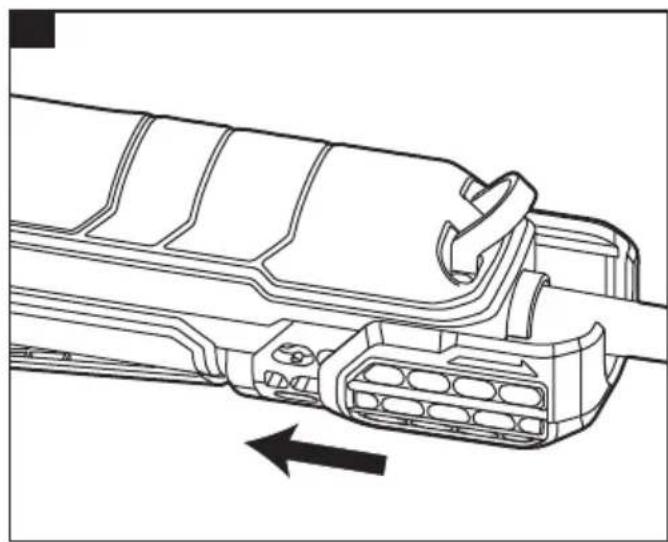
Dust filter (see figure E1-E2)
■ Regularly clean the filter cover (5).
■ Remove filter cover (5) and blow it out with dry compressed air.
Switching on and off
For LB 20-11 125-EC, LBE 20-11 125-EC, LBE 20-10 150-EC, LBE 20-8 125-EC INOX
Brief operation without engaged switch rocker (see figure F1)
■ Press the switch rocker (1.), push forwards front and hold (2.).
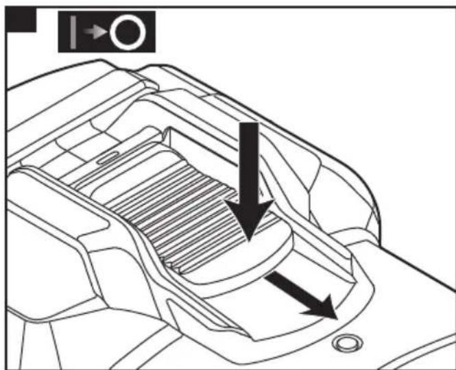
■ To switch off, release the switch rocker (1).
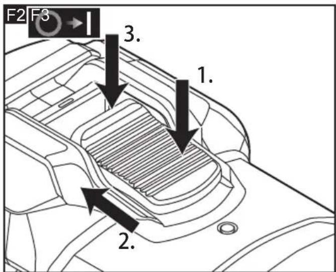
Continuous operation with engaged switch rocker (see figure F2-F3)
■ Press the switch rocker (1.), push forwards front and hold (2.) and engage at front end by applying pressure (3.).
■ To switch off, briefly press and release the switch.
For LBP 20-11 125-EC (see figure F4)
■ To start the tool, pull the paddle lock-off lever (13) forward (1.) and squeeze the paddle switch (2.).
■ To stop the tool, release the paddle switch (12). Make sure the tool comes to a complete stop before laying the tool down
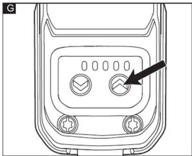
Preselecting the speed (see figure G)
For LBE 20-11 125-EC, LBE 20-10 150-EC, LBE 20-8 125-EC INOX
■ To set the operating speed, press the speed control button (3). Selected speed is maintained even when switching off.

CAUTION!
Risk of injury due to destruction of the tool. Use the appropriate tool for the job.
Adjusting the guard (see figure H)
To adjust the tool to the task at hand, the guard hood can be adjusted by the notches on 360^ without a tool.
Operating

NOTE
When the power tool is switched off, the tool continues running briefly.

WARNING!
Always wear safety goggles or a face shield during operation.

WARNING!
To maintain proper control, always operate the tool with two hands, keeping one hand on the auxiliary handle. Loss of control could cause an accident resulting in possible serious injury.
Rough-grinding

WARNING!
Never use cutting-off wheels for rough-grinding.
- Angle of wheel 20-40° for best grinding performance.
- Applying moderate pressure, move the angle grinder backwards and forwards. As a result, the workpiece will not become too hot and there will be no discoloration, nor will there be any grooves.
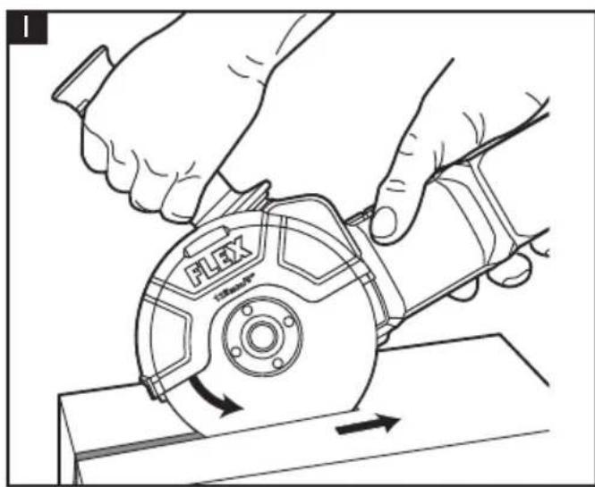
Cut-off grinding (see figure I)

WARNING!
Always use protective guard for cutting when performing cut-off grinding operations
- The angle grinder shall always be operated backwards. Otherwise, there is a risk of the angle grinder jumping uncontrollably out of the groove.
- Do not press, tilt or oscillate the power tool.
- Adjust the feed to the material which is to be cut: the harder the material, the slower the feed.
Cup brush/disc brush/conical brush
Always use the protection guard for grinding, when brushing with disc brushes.
Working with diamond hole cutter
Only use dry diamond hole cutter.
It is recommended to use the protection guard for grinding when working with diamond hole cutter.
Do not place the diamond hole cutter parallel to the workpiece. Plunge it into the workpiece at an angle and in a circular motion. This will allow you to achieve optimal cooling and ensure a longer tool life for the diamond hole cutter.
Maintenance and care

WARNING!
Before carrying out any work on the angle grinder, always pull out the mains plug.
Cleaning

WARNING!
If metals are ground or cut over a prolonged period, conductive dust may become deposited inside the housing.
■ Clean the power tool and grille in front of the vent slots regularly. Frequency of cleaning is dependent on the material and duration of use.
■ Regularly blow out the housing interior and motor with dry compressed air.

NOTE
Use only original parts supplied by the manufacturer for replacement purposes. If non-original parts are used, the guarantee obligations of the manufacturer will be deemed null and void.

NOTE
Do not loosen the screws during the warranty period. Non-compliance will deem the guarantee obligations of the manufacturer null and void.
Repairs
Repairs may be carried out by an authorised customer service centre only.
Spare parts and accessories
For other accessories, in particular tools, see the manufacturer's catalogues.
Exploded drawings and spare-part lists can be found on our homepage:
www.flex-tools.com
The instruction can also be available on www.flex-tools.com.
Disposal information

WARNING!
Render redundant power tools unusable: - mains operated power tool by removing the power cord,

EU countries only
Do not throw electric power tools into the household waste!
In accordance with the European Directive 2012/19/EU on Waste Electrical and Electronic Equipment and transposition into national law used electric power tools must be collected separately and recycled in an environmentally friendly manner.

Raw material recovery instead of waste disposal.
Device, accessories and packaging should be recycled in an environmentally friendly manner. Plastic parts are identified for recycling according to material type.

NOTE
Please ask your dealer about disposal options!
CE Declaration of conformity
We declare on our sole responsibility that the product described in "Technical specifications" conforms to the following standards or normative documents:
EN 62841-1:2015+A11:2022
EN IEC 62841-2-3:2020+A11:2021
EN IEC 55014-1:2021
EN IEC 55014-2:2021
EN 61000-3-2:2019+A1:2021
EN 61000-3-3:2013+A1:2019
EN IEC 63000:2018 in accordance with the regulations of the directives 2014/30/EU, 2006/42/EC, 2011/65/EU.
Responsible for technical documents:
Technical Head Head of Quality
Department (QD)
Declaration of Conformity
We as the manufacturer: FLEX Elektrowerkzeuge GmbH, Business address: Bahnhofstr. 15, 71711 Steinheim, Germany declare under our sole responsibility, that the product(s) described under „Technical specifications“ fulfills all the relevant provisions of The Supply of Machinery (Safety) Regulations S.I. 2008/1597 and also fulfills all the relevant provisions of the following UK Regulations: Electromagnetic Compatibility Regulations S.I. 2016/1091, The Restriction of the Use of Certain Hazardous Substances in Electrical and Electronic Equipment Regulations S.I. 2012/3032 and are manufactured in accordance with the following designated Standards: EN 62841-1:2015+A11:2022 EN IEC 62841-2-3:2020+A11:2021 EN IEC 55014-1:2021 EN IEC 55014-2:2021 EN 61000-3-2:2019+A1:2021 EN 61000-3-3:2013+A1:2019 EN IEC 63000:2018 Place of declaration: Steinheim, Germany. Responsible person: Peter Lameli, Technical Director - FLEX-Elektrowerkzeuge GmbH Authorized to compile the technical file: FLEX Power Tools Limited, Unit 8 Anglo Office Park, Lincoln Road, HP 12, 3RH Buckinghamshire, United Kingdom.

Peter Lameli Klaus Peter Weinper Technical Head Head of Quality Department
1.09.2024
Exemption from liability
The manufacturer and his representative are not liable for any damage and lost profit due to interruption in business caused by the product or by an unusable product. The manufacturer and his representative are not liable for any damage which was caused by improper use of the product or by use of the product with products from other manufacturers.
Table des matières
EN IEC 62841-2-3:2020+A11:2021
EN CEI 55014-1:2021
EN CEI 55014-2:2021
EN 61000-3-2:2019+A1:2021
EN 61000-3-3:2013+A1:2019
EN IEC 62841-2-3:2020+A11:2021
EN IEC 55014-1:2021
EN IEC 55014-2:2021
EN 61000-3-2:2019+A1:2021
EN 61000-3-3:2013+A1:2019
EN IEC 62841-2-3:2020+A11:2021
EN IEC 55014-1:2021
EN IEC 55014-2:2021
EN 61000-3-2:2019+A1:2021
EN 61000-3-3:2013+A1:2019
EN IEC 62841-2-3:2020+A11:2021
EN IEC 55014-1:2021
EN IEC 55014-2:2021
EN 61000-3-2:2019+A1:2021
EN 61000-3-3:2013+A1:2019
EN IEC 63000:2018 de acordo com as normas das diretivas 2014/30/UE, 2006/42/EC e 2011/65/UE.
EN IEC 62841-2-3:2020+A11:2021
EN IEC 55014-1:2021
EN IEC 55014-2:2021
EN 61000-3-2:2019+A1:2021
EN 61000-3-3:2013+A1:2019
EN IEC 62841-2-3:2020+A11:2021
EN IEC 55014-1:2021
EN IEC 55014-2:2021
EN 61000-3-2:2019+A1:2021
EN 61000-3-3:2013+A1:2019
EN IEC 63000:2018 i samsvar med forskriftene i direktivene 2014/30/EU,
2006/42/EC, 2011/65/EU.
Ansvarlig for tekniske dokumenter: FLEX-Elektrowerkzeuge GmbH, R & D Bahnhofstrasse 15, D-71711 Steinheim/Murr

EN IEC 62841-2-3:2020+A11:2021
EN IEC 55014-1:2021
EN IEC 55014-2:2021
EN 61000-3-2:2019+A1:2021
EN 61000-3-3:2013+A1:2019
EN IEC 62841-2-3:2020+A11:2021
EN IEC 55014-1:2021
EN IEC 55014-2:2021
EN 61000-3-2:2019+A1:2021
EN 61000-3-3:2013+A1:2019
EN 63000:2018 -standardin, direktiivien
EN IEC 62841-2-3:2020+A11:2021
EN IEC 55014-1:2021
EN IEC 55014-2:2021
EN 61000-3-2:2019+A1:2021
EN 61000-3-3:2013+A1:2019
EN IEC 62841-2-3:2020+A11:2021
EN IEC 55014-1:2021
EN IEC 55014-2:2021
EN 61000-3-2:2019+A1:2021
EN 61000-3-3:2013+A1:2019
EN IEC 62841-2-3:2020+A11:2021
EN IEC 55014-1:2021
EN IEC 55014-2:2021
EN 61000-3-2:2019+A1:2021
EN 61000-3-3:2013+A1:2019
EN IEC 62841-2-3:2020+A11:2021
EN IEC 55014-1:2021
EN IEC 55014-2:2021
EN 61000-3-2:2019+A1:2021
EN 61000-3-3:2013+A1:2019
EN IEC 62841-2-3:2020+A11:2021
EN IEC 55014-1:2021
EN IEC 55014-2:2021
EN 61000-3-2:2019+A1:2021
EN 61000-3-3:2013+A1:2019
EN IEC 63000:2018 v súlade s predpismi smerníc 2014/30/EÚ, 2006/42/EC, 2011/65/EÚ.
EN IEC 62841-2-3:2020+A11:2021
EN IEC 55014-1:2021
EN IEC 55014-2:2021
EN 61000-3-2:2019+A1:2021
EN 61000-3-3:2013+A1:2019
EN IEC 63000:2018 u skladu s uredbama direktiva 2014/30/EU, 2006/42/EC, 2011/65/EU.
Osoba odgovorna za tehničku dokumentaciju: FLEX-Elektrowerkzeuge GmbH, R & D Bahnhofstrasse 15, D-71711 Steinheim/Murr

Peter Lameli Klaus Peter Weinper Tehnički direktor Voditelj odjela za kontrolu kvalitete (QD)
Hrup in tresljaji 204
EN IEC 62841-2-3:2020+A11:2021
EN IEC 55014-1:2021
EN IEC 55014-2:2021
EN 61000-3-2:2019+A1:2021
EN 61000-3-3:2013+A1:2019
EN IEC 63000:2018 v skladu s predpisi direktiv 2014/30/EU, 2006/42/EC, 2011/65/EU.
EN IEC 62841-2-3:2020+A11:2021
EN IEC 55014-1:2021
EN IEC 55014-2:2021
EN 61000-3-2:2019+A1:2021
EN 61000-3-3:2013+A1:2019
EN IEC 62841-2-3:2020+A11:2021
EN IEC 55014-1:2021
EN IEC 55014-2:2021
EN 61000-3-2:2019+A1:2021
EN 61000-3-3:2013+A1:2019
EN IEC 62841-2-3:2020+A11:2021
EN IEC 55014-1:2021
EN IEC 55014-2:2021
EN 61000-3-2:2019+A1:2021
EN 61000-3-3:2013+A1:2019
EN IEC 62841-2-3:2020+A11:2021
EN IEC 55014-1:2021
EN IEC 55014-2:2021
EN 61000-3-2:2019+A1:2021
EN 61000-3-3:2013+A1:2019
EN 63000:2018 pagal reglamentus
direktyvose 2014/30/ES, 2006/42/EC, 2011/65/ES.
Uż techninę dokumentaciją atsakingi asmenys: FLEX - Elektrowerkzeuge GmbH, R & D
Bahnhofstrasse 15, D-71711 Steinheim/Murr

Peter Lameli Klaus Peter Weinper Techninis Kokybès skyriaus vadovas direktorius
EN IEC 62841-2-3:2020+A11:2021
EN IEC 55014-1:2021
EN IEC 55014-2:2021
EN 61000-3-2:2019+A1:2021
EN 61000-3-3:2013+A1:2019
EN IEC 63000:2018 saskaṇā ar Direktīvas
Nr. 2014/30/EK, 2006/42/EC un 2011/65/ES noteikumiem.
(EC, LBE 20-8 125-EC INOX
EN IEC 62841-2-3:2020+A11:2021
EN IEC 55014-1:2021
EN IEC 55014-2:2021
EN 61000-3-2:2019+A1:2021
EN 61000-3-3:2013+A1:2019


- Inhalt
- Symbols used in this manual
- WARNING!
- CAUTION!
- NOTE
- Symbols on the product
- Important safety information
- Intended use
- Safety instructions for angle grinder
- Further safety instructions for all operations
- ⚠️ Kickback and Related Warnings:
- Additional safety instructions for grinding and cutting-off operations
- Safety warnings specific for grinding and cutting-off operations:
- Additional safety instructions for cutting-off operations
- Additional safety warnings specific for cutting-off operations:
- Safety warnings specific for sanding operations:
- Safety warnings specific for wire brushing operations:
- Additional safety instructions
- Noise and vibration
- Overview (Figure A)
- Switch rocker
- Rear handle
- Speed control button
- Power cord with plug
- Filter cover
- Auxiliary handle
- Protective guard for grinding
- Threaded flange
- Spindle
- Gear head
- Spindle lock
- Paddle switch
- Paddle Lock-off lever
- Protective clip on guard for cutting
- Pin wrench
- Tether mount
- Operating instructions
- Before switching on the power tool
- Installing and removing the protective guard (see figure B1-B3)
- To install the guard
- Auxiliary handle (see figure C)
- Installing and removing the grinding or cutting wheel (see figure D1-D3)
- To install the wheel
- To remove the wheel
- Dust filter (see figure E1-E2)
- Switching on and off
- Brief operation without engaged switch rocker (see figure F1)
- Continuous operation with engaged switch rocker (see figure F2-F3)
- For LBP 20-11 125-EC (see figure F4)
- Preselecting the speed (see figure G)
- For LBE 20-11 125-EC, LBE 20-10 150-EC, LBE 20-8 125-EC INOX
- Adjusting the guard (see figure H)
- Operating
- Rough-grinding
- Cut-off grinding (see figure I)
- Cup brush/disc brush/conical brush
- Working with diamond hole cutter
- Maintenance and care
- Cleaning
- Repairs
- Spare parts and accessories
- Disposal information
- Raw material recovery instead of waste disposal.
- CE Declaration of conformity
- Declaration of Conformity
- Exemption from liability
- Table des matières
Brand : Flex
Model : LBE 20-10 150-EC
Category : Grinder