USER MANUAL CZ-RTW1 PANASONIC
Operating Instructions
Wired Remote Controller
Model No. CZ-RTW1
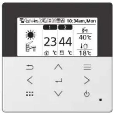
Thank you for purchasing Panasonic product.
Any translation into other language shall be deemed as reference and English version shall prevail in any case.
The illustrations in this manual are for explanation purposes only and may differ from the actual unit. They are subject to change without notice.
Table of contents
Safety precautions 2-3
Remote Controller buttons and display 4-5
Initialization 6
Quick Menu 7
How to use the Quick Menu 8-12
Menus 13-17
1 Function setup ......13-14
1.1 Weekly timer
1.2 Holiday timer
1.3 Quiet timer
1.4 Quiet priority
1.5 Room heater
1.6 Tank heater
1.7 Sterilization
1.8 DHW mode
2 System check 15
2.1 Energy monitor
2.2 System information
2.3 Error history
2.4 Compressor
2.5 Heater
3 Personal setup 16-17
3.1 Remote control No.
3.2 Touch sound
3.3 LCD contrast
3.4 Backlight
3.5 Backlight intensity
3.6 Clock format
3.7 Date & Time
3.8 Language
3.9 Unlock password
Troubleshooting 18
Information 19
Safety precautions
To prevent personal injury, injury to others or property damage, please comply with the following: Incorrect operation due to failure to follow instructions below may cause harm or damage, the seriousness of which is classified as below:
This appliance is not intended for accessibility by the general public.

WARNING
This sign warns of death or serious injury.

CAUTION
This sign warns of injury or damage to property.
The instructions to be followed are classified by the following symbols:

This symbol denotes an action that is PROHIBITED.

These symbols denote actions COMPULSORY.

WARNING

This can cause electric shock or ignition.
- Do not disassemble or modify.
- Do not touch with wet hands.
- Do not wipe with wet cloths or wash in water.

This application is not intended for use by persons (including children) with reduced physical, sensory or mental capabilities, or lack of experience and knowledge, unless under supervision or instruction concerning use of the appliance by a person responsible for their safety. Children should be supervised to ensure they do not play with the appliances.
Request installation only from the place of purchase or an installer.
- Not doing so may cause electric shock or ignition.
Shut off power supply when installing CNT cable. - Not doing so may cause electric shock or ignition.
Use only the specified parts when installing CNT cable and perform the installation correctly by following the instructions.
- Not doing so may cause electric shock or ignition.
Ensure cables are installed properly so that external forces cannot affect them. - Not doing so may lead to overheating which can lead to ignition.
Stop use as soon as any problems or malfunctions are detected and shut off the electric supply to connected appliances.
- Not doing so may cause smoke, ignition, electric shock, or burns. • Examples of problems and malfunctions:
- There is a burning smell
- Water or foreign objects have gotten inside
- Immediately request repair from the place of purchase or the installer.

CAUTION

Before connecting wires and cables, discharge any static electricity.
- Not doing so may cause malfunction.
Check the following requirements in advance:
- There should be no abnormality in the air conditioner such as change of airflow. Ensure no object(s) which may be displaced easily due to the airflow blowing directly at it. The fallen or moved object(s) might lead to danger such as fire, injury etc.
The LCD display shown in this manual is for instructional purposes only and may differ from the actual unit.
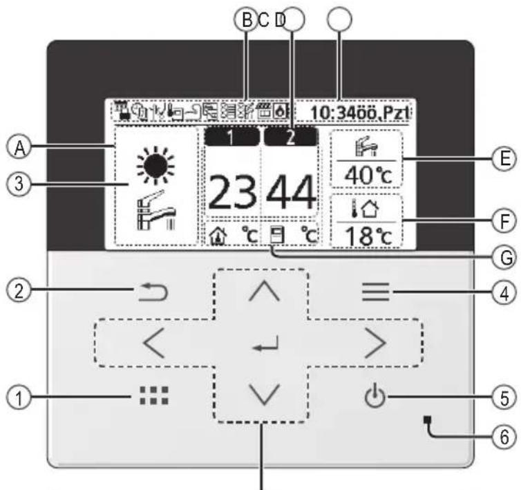
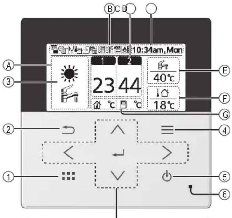
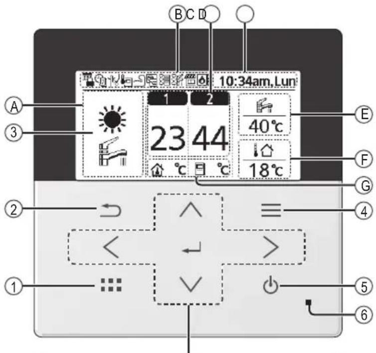
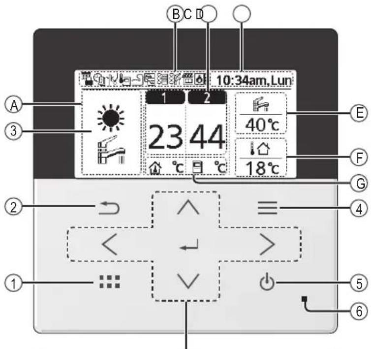
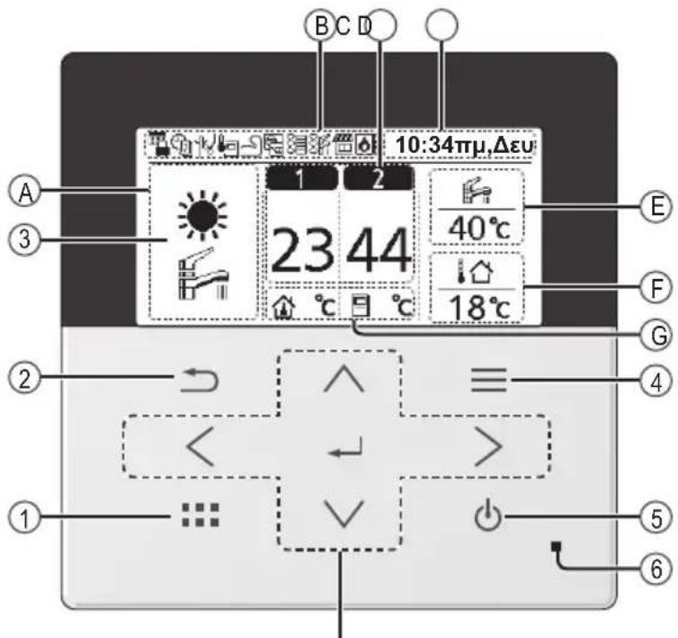
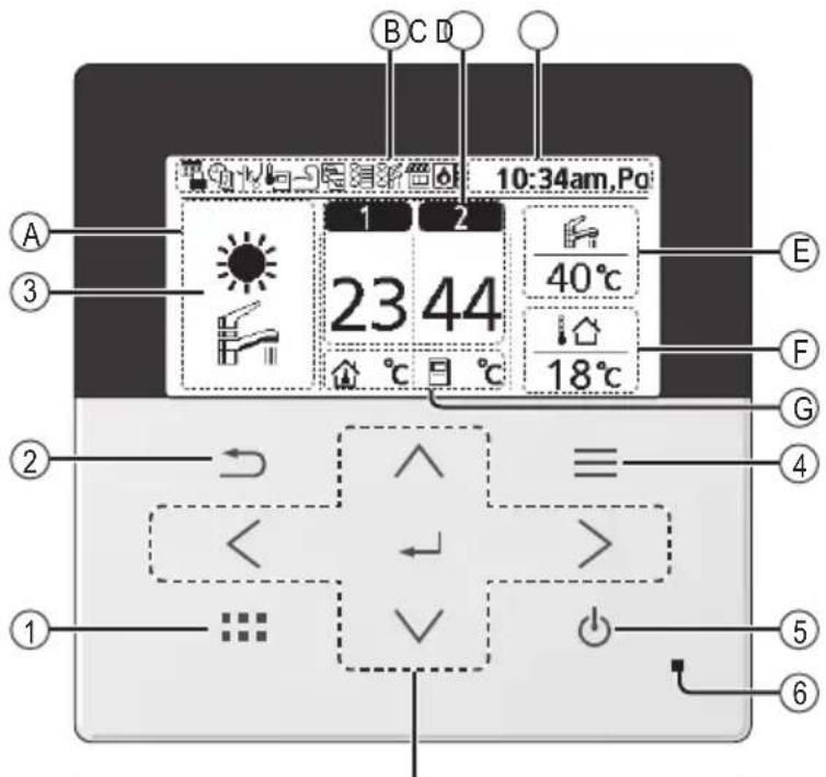
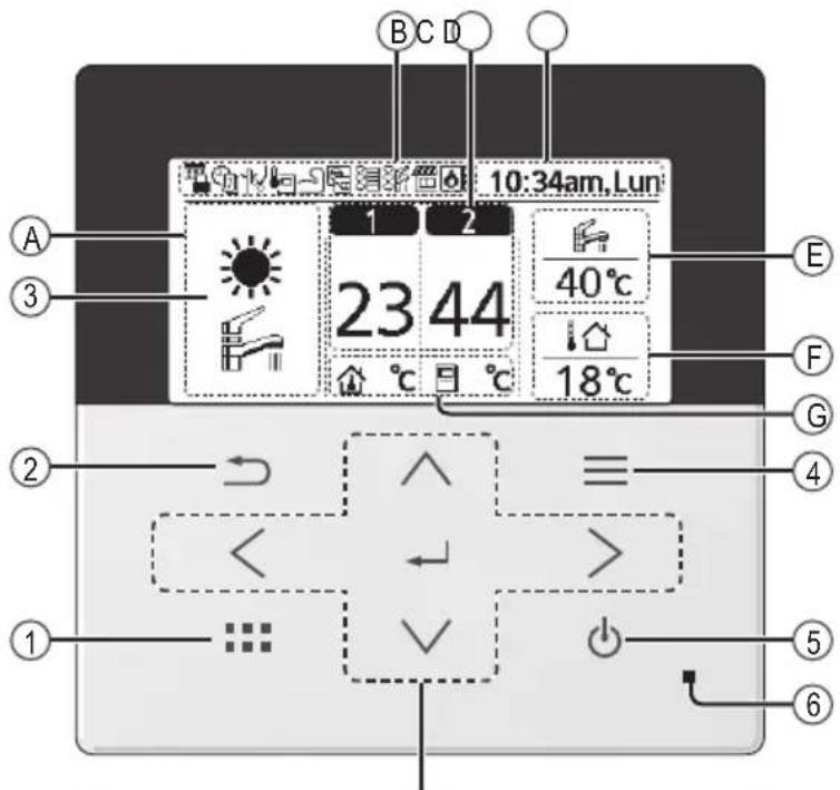
① Quick Menu button Back button Returns to the previous screen LCD Display (Actual - Dark background with white icons) Main Menu button For function setup 5 ON/OFF button Starts/Stops operation Operation indicator ⑥ Illuminates during operation, blinks during alarm.

Press centre
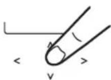
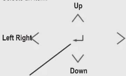
Cross key buttons
Selects an item.

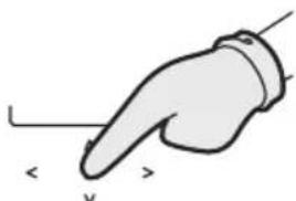
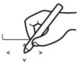
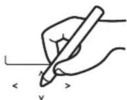
No glove

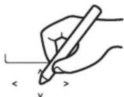
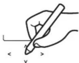
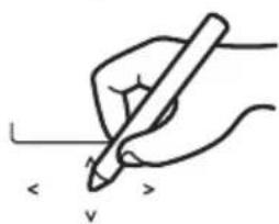
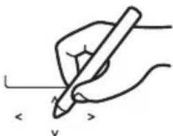
No pen
Enter button
Fixes the selected content.
| A Mode selection |
| *1, *2 AUTO | ·Depending on the preset outdoor temperature, the system selects HEAT or *1, *2 COOL operation mode. | *1, *2 COOL operation is either turned ON or OFF.
·The outdoor unit provides cooling to the system. |
| *1, *2 AUTO + TANK | ·Depending on the preset outdoor temperature, the system selects HEAT + TANK or *1, *2 COOL + TANK operation mode. | *1, *2 COOL + TANK
·The outdoor unit provides cooling to the system.
·The outdoor unit provides heating when boiling tank. |
| HEAT | ·HEAT operation is either turned ON or OFF.
·The outdoor unit provides heat to the system. | TANK operation is either turned ON or OFF.
·The outdoor unit provides heat to the water tank. |
| HEAT + TANK | ·The outdoor unit provides heat to the water tank and the system.
·This mode can be selected only when the water tank is installed. | * The direction icons point to the currently active mode.
Room operation / Tank operation.
Deice operation. |
| B Operation icons
The status of operation is displayed.
Icon will not display (under operation OFF screen) whenever operation is OFF except weekly timer.
Holiday operation status Weekly Timer operation status Quiet operation status
Zone: Room Thermostat →Internal sensor status Powerful operation status Demand Control or SG ready or SHP status
Room Heater status Tank Heater Status Solar status
Bivalent status (Boiler) |
| C Temperature of each zone |
| D Time and day |
| E Water Tank temperature |
| F Outdoor temperature |
| G Sensor type/Set temperature type icons |
| Water Temperature →Compensation curve | Water Temperature →Direct | Pool only |
| Room Thermostat →External | Room Thermostat →Internal | Room Thermistor |
* The system is locked to operate without COOL mode. It can be unlocked only by authorised installers or our authorised service partners.
* Only displayed when COOL mode is unlocked (This means when COOL mode is available).
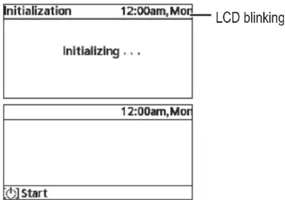
Before starting to install the various menu settings, please initiate the Remote Controller by selecting the language of operation and installing the date and time correctly.
When power is turned on for the first time, it becomes the setting screen automatically. It can also be set from personal setting of the menu.
Wait while the display is initializing. When initializing screen ends, it turns to normal screen.
① On first power ON, initialization screen will appear on Second remote controller. ② After installer has selected "Dual" on Remote control setup, please wait for at least 30 seconds for synchronisation between Main remote controller (RC-1) & Second remote controller (RC-2) to take place before operating this Second remote controller.
*NOTE: All buttons are disabled on the second remote controller until the synchronization process completes.
③ Then this remote controller is ready to be used.
*NOTE: Any setting adjustment on RC-2 will be reflected on RC-1 and vice versa. Generally, there will be around 10 seconds idle required for synchronization between RC-1 and RC-2. Sometimes there will be a pop-up message of “RC-1 & RC-2 sync. in progress!” when RC-2 is trying to synchronize with RC-1.
After the initial settings have been completed, you can select a quick menu from the following options and edit the setting.
![Select [~] ON/OFF](/content/2026/04/669872/images/7ff4a5ef0a852cecddfa03c9aed8d29599b7eaae10c08ee80d91fbd338dea446.jpg)
② Use ^ to select menu.
③ Press ← to turn on/off the select menu.![Quick Menu Force DHW Powerful Quiet Force Heater Weekly Timer Force Defrost Error Reset Lock Select [←]ON/OFF Select each setting and confirm the setting according to the instructions displayed at the bottom of the screen. (The icons refer to each selection key.)](/content/2026/04/669872/images/fdf035fb42f92e9f33ea1742e1aa41323bb5dd907eea62ac2f50e589dd894c4a.jpg)
To return to the Main Screen,
Press or .

Force DHW
Select this icon to turn the Tank DHW on or off.
Press ← to confirm your selection.
![graph TD A["Start"] --> B{Condition} B -->|Yes| C["Valve Icon"] B -->|No| D["Valve Icon"] C --> E["Downward Arrow"] D --> F["Downward Arrow"]](/content/2026/04/669872/images/d83f2886e126a475782816d4e62a2e4101d433e2d197993ea0fe45c031554fbd.jpg)
- Force DHW is turned off.
- Force DHW is turned on.
Note:
- Force DHW is disabled when Force Heater is turned on.
- When Force DHW is turned off, operation and mode should revert to the previously memorized status.

Powerful
Select this icon to operate the heating/cooling system powerfully.
Press ← to confirm your selection.
(The powerful operation starts approximately 1 minute after ← is pressed.)
![graph TD A["Start"] --> B{Powerful mode is set off.} B --> C["30 minutes"] C --> D{The Powerful mode operates for 30 minutes.} D --> E["60 minutes"] E --> F{The Powerful mode operates for 60 minutes.} F --> G["90 minutes"] G --> H{The Powerful mode operates for 90 minutes.}](/content/2026/04/669872/images/bf1a65b62b99b192ccc24c5042d069b75b890ad5d85f10733aedd4cdf0c3b2b7.jpg)
Note:
- Powerful is disabled when operation is turned OFF.

Quiet
Select this icon to operate quietly.
Press ← to confirm your selection.
(The quiet operation starts approximately 1 minute after ← is pressed.)
![graph TD A["Start"] --> B{Quiet mode is set off.} B --> C["Level 1"] C --> D{The Quiet mode operates at level 1.} D --> E["Level 2"] E --> F{The Quiet mode operates at level 2.} F --> G["Level 3"] G --> H{The Quiet mode operates at level 3. Level 3 is the most quiet mode.} H --> I["Select this to se…](/content/2026/04/669872/images/718b195d9d5716a8fa90a5d831f66564cf82e5c3f43241efbe27b6c53b6a89d7.jpg)
![graph TD A["Do you want to edit Quiet timer pattern?"] --> B{Yes} B -->|No| C["Select "Yes". Select "Yes" using < > buttons."] C --> D["1 6:00 am 2"] D --> E["2 8:00 pm 1"] E --> F["3 10:00 pm 0"] F --> G["Edit\nDelete"] G --> H["12:00 pm"] H --> I["Set the hour and minutes."] I…](/content/2026/04/669872/images/663885b372d40d9a444752aa4ab095ee9c9b92746d945c19e0c54d19f9f8d14b.jpg)

Force Heater
Select to force the Heater on.
Press ← to confirm your selection.
(The Force Heater mode starts approximately 1 minute after is pressed.)
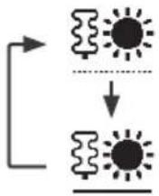
- Force Heater is turned off.
- Force Heater is turned on.
Note:
- Force Heater is disabled whenever operation is already on and "Disabled due to operation ON!" will be displayed.
Disabled due to operation ON!
[→]Close

Weekly Timer
Select this icon to delete (cancel) or change the pre-set Weekly Timer.
Press ← to confirm your selection.
![graph TD A["Timer not ON"] --> B["Timer set"] B --> C["After 1 sec delay"]](/content/2026/04/669872/images/da80ba89043cfe2dfcde5a044fa408a77ce1cda57bd02486b00f42ed31c1f87e.jpg)
![graph TD A["Do you want to edit Weekly timer pattern?"] --> B{Yes} B -->|No| C["Timer setup"] C --> D["Timer copy"] D --> E["Sun Mon Tue Wed Thu Fri Sat"] E --> F{All 6 patterns are not set! Do you want to edit?} F -->|Yes| G["No"] F -->|No| H[< img src="box123450000000000000000000000000000000000000…](/content/2026/04/669872/images/013a5b8642096c1ced677a44161bb48ab7c2d722e7924fdc7069ecdebc71825d.jpg)
Select "Yes".
- If you select "No", the screen will return to the Main Screen.
- Timer setup: Select Timer setup to edit the Weekly Timer.
- Timer copy: Select to copy a timer setting.
[Example of a Timer setup]
Select the day(s) which you wish to edit using ^buttons.
If all 6 patterns are not preset, this screen will be displayed.

① Select pattern "1" to "6". ② Set the hour and minutes of the Timer. ③ Select ON/OFF of the Timer. ④ Select the operation mode. - Select mode using the ^ buttons. ⑤ Set the temperature for both Zone 1 and 2 (if your system has the 2-Zone setting).
![PANASONIC CZ-RTW1 - [Example of a Timer setup] - 2](/content/2026/04/669872/images/ac37c7874ddb49adcfec0b30ecbc5c2c9f5ec84494a268dc8ad9f1d8e49261e9.jpg)
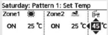
⑥ Set the Tank temperature.
Note:
- Timer is disabled when Force Heater is turned on or Heat-Cool SW is enabled.
- If you have preset the Weekly Timer on 2 zones, you must repeat the same procedure with Zone 2.

Force Defrost
Select to defrost the frozen pipes.
Press ← to confirm your selection.
(When the mode is accepted, the following screen will be displayed.)
Request accepted!
[→] Close

Error Reset
Select to restore the previous settings when an error has occurred.
Press ← to confirm your selection.
(When the mode has been accepted, the following screen will be displayed.)
Request accepted!
[→] Close
- Make sure all units are turned off before selecting this mode, which restores the whole system to the previous settings.

R/C Lock
Select to lock the Remote Controller.
Press ← to confirm your selection.
(When the mode has been accepted, the following screen will be displayed.)
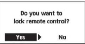
Select "Yes".
(The Main Screen will be locked.)
- If "No" is selected, the screen will return to the Main Screen.
To unlock the Remote Controller
Press any key.
(When the mode has been accepted, the following screen will be displayed.)
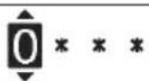
Enter any 4 digits of number (if the number is correct, the screen will be unlocked).
To reset forgotten password (under operation OFF screen)
Press and hold , and continuously for 5 seconds.
(When the mode has been accepted, the following screen will be displayed.)
![graph TD A["Reset password"] --> B["Reset"] B --> C["1. Password is reset to 0000\n2. Remote control is unlocked"]](/content/2026/04/669872/images/337c4582aed9f9e76b7bd2c9c9e66e0d30bf6a61a5b2995c821b5154540c6b5e.jpg)
Select "Reset".
(The screen will turn off after 3 seconds.)
Select menus and determine settings according to the system available in the household. All initial settings must be done by an authorized dealer or a specialist. It is recommended that all alterations of the initial settings are also done by an authorized dealer or a specialist.
• After initial installation, you may manually adjust the settings. - The initial setting remains active until the user changes it. - The Remote Controller can be used for multiple installations. - Ensure the operation indicator is OFF before setting. • The system may not work properly if set incorrectly. Please consult an authorized dealer.
To display:

To select menu: ^ ∨ < >
To confirm the selected content:

![Main Menu 10:34am, Mon Function setup System check Personal setup Service contact Select [+] Confirm](/content/2026/04/669872/images/5753c14d22ee334883414e2284f9ec448f72e883a4da2f4febda17141314beaf.jpg)
1 Function setup
1.1 > Weekly timer
Once the weekly timer is set up, the user can edit it from the Quick Menu. To set up to 6 patterns of operation on a daily basis.
- Disabled if Heat-Cool SW is set to "Yes" or if Force Heater is on.
Timer setup
Select day of the week and set the patterns needed (Time / Operation ON/OFF / Mode)
Timer copy
Select day of the week
| Weekly timer 10:34am, Mon |
| Sun | Mon | Tue | Wed | Thu | Fri | Sat |
| 1. | 8:00am | ON | | | | 40°C |
| 2. | 12:00pm | ON | | 24/28°C | | 40°C |
| 3. | 1:00pm | ON | | 12/10°C | | |
| ←Day | Pattern | [←]Edit |
1.2 > Holiday timer
To save energy, a holiday period may be set to either turn OFF the system or lower the temperature during the period.
OFF
ON
OFF
>ON
Holiday start and end.
Date and time
OFF or lowered temperature
| Holiday: End | 10:34am,Mon |
| Year/Month/Day | Hour : Min |

/01 / 01
10:00 am
Select Confirm [←]
1.3 >Quiet timer
To operate quietly during the preset period.
6 patterns may be set.
Level 0 means the mode is off.
Time to start Quiet : Date and time
Level of quietness: 0 \~ 3
| Quiet 10:34am, Mon |
| Pattern | Time | Level |
| 1 | 8:00 am | 0 |
| 2 | 5:00 pm | 1 |
| 3 | 11:00 pm | 3 |
| Select | [-] Edit | |
| Menu Default Setting Setting Options / Display | |
| 1.4 > Quiet priority |
| • To select priority during Quiet mode between Sound and Capacity.• If Sound priority is selected, unit will operate in quiet condition only.• If Capacity priority is selected, unit will operate in quiet condition but it will prioritize on providing required capacity at the same time. | Sound | 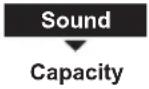 |
| 1.5 > Room heater |
| To set the room heater ON or OFF. | OFF |  |
| 1.6 > Tank heater |
| To set the tank heater ON or OFF. | OFF | ON  |
| 1.7 > Sterilization |
| To set the auto sterilization ON or OFF. | ON | 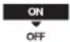 |
| • Do not use the system during sterilization in order to prevent scalding with hot water, or overheating of shower.• Ask an authorised dealer to determine the level of sterilization function field settings according to the local laws and regulations. |
| 1.8 > DHW mode (Domestic Hot Water) |
| To set the DHW mode to Standard or Smart.• Standard mode have faster DHW Tank heat up time. Meanwhile Smart mode take longer time to heat up DHW time with lower energy consumption. | Standard | StandardSmart |
| To set the tank sensor to Top or Center.• Selection of the tank sensor to top slow down the start of boiling up the tank and reduce power consumption. Please change this selection to “Center” when the hot water becomes insufficient. | Top | 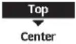 |
| 2 System check |
| 2.1 > Energy monitor |
| Present or historical chart of energy consumption, generation or COP. | PresentSelect and retrieve | Total consumption (1year)0.0kWh1year 1 2 3 4 5 6 7 8 9 1 0 1 C.MHJan, 2022: 0.0 kWh Approx.Month Mode |
| Historical chartSelect and retrieve |
| ·COP= Coeffi cient of Performance.·For historical chart, the period is selected from 1 day/1 week/1year.·Energy consumption (kWh) of heating, *1, *2 cooling, tank and total may be retrieved.·The total power consumption is an estimated value based on AC 230 V and may differ from value measured by precise equipment. |
| 2.2 > System information |
| Shows all system information in each area. | Actual system information of 11 items:Inlet / Outlet / Zone 1 / Zone 2 / Tank / Buffer tank / Solar / Pool / COMP frequency / Pump flowrate / Water pressureSelect and retrieve | System information 10:34am, Mon1. Inlet : 0°C2. Outlet : 0°C3. Zone 1 : 0°C4. Zone 2 : 0°CPage |
| 2.3 > Error history |
| ·Refer to Troubleshooting for error codes.·The most recent error code is displayed at the top. | Select and retrieve | Error history 10:34am, Mon1. --2. --3. --4. --[--]Clear history |
| 2.4 > Compressor |
| Shows the compressor performance. | Select and retrieve | Compressor 10:34am, Mon1. Current frequency : 0 Hz2. (OFF-ON) counter : 03. Total ON time : 0 h[→]Back |
| 2.5 > Heater |
| Total hours of ON time for Room heater/Tank heater. | Select and retrieve | Heater 10:34am, MonTotal ON time: Oh: Oh[→]Back |
*1 The system is locked to operate without COOL mode. It can be unlocked only by authorised installers or our authorised service partners.
*2 Only displayed when COOL mode is unlocked (This means when COOL mode is available).
| Menu Default Setting Setting Options / Display | |
| 3 Personal setup |
| 3.1 > Remote control No. |
| • To display remote control number of a particular remote controller so that installer and end user are well informed.• Main remote controller is displayed as RC-1. Second remote controller is displayed as RC-2. | Select and retrieve | RC No. 10:34am,Mon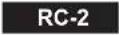  |
| 3.2 > Touch sound |
| Turns the operation sound ON/OFF. | ON |  |
| 3.3 > LCD contrast |
| Sets the screen contrast. | 3 | LCD contrast 10:34am,Mon  |
| 3.4 > Backlight |
| Sets the duration of screen backlight. | 1 min | 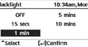 |
| 3.5 > Backlight intensity |
| Sets screen backlight brightness. | 4 | Backlight intensity 10:34am,Mon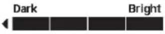  |
| 3.6 > Clock format |
| Sets the type of clock display. | am/pm | Clock format 10:34am,Mon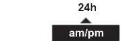 *Select Confirm[-] *Select Confirm[-] |
| 3.7 > Date & Time |
| Sets the present date and time. | Year / Month / Day / Hour / Min | 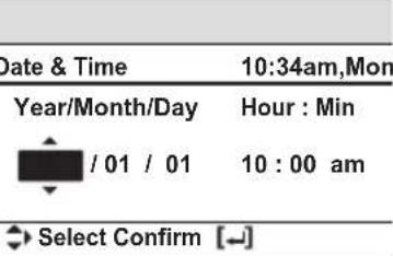 |
| Menu Default Setting Setting Options / Display | |
| 3.8 >Language |
| Sets the display language for the top screen. | ENGLISH / FRANÇAIS / DEUTSCH / ITALIANO / ESPAÑOL / DANISH / SWEDISH / NORWEGIAN / POLISH / CZECH / NEDERLANDS / TÜRKÇE / SUOMI / MAGYAR / SLOVENŠČINA / HRVATSKI / LIETUVIŲ / PORTUGUĖS / БЪЛГАРСКИ / EESTI / LATVIEŠU / ROMÂNĂ / SHQIP / SLOVENČINA / MAKEDОНСКИ / УКРАЇНСЬКА / ЕЛАННИКА | Language 10:34am, Mon |
| ENGLISHFRANÇAISDEUTSCHITALIANOSelect [←] Confirm |
| 3.9 >Unlock password |
| 4 digit password for all the settings. | 0000 | | Unlock password 10:34am, Mon |
| ○○○○○○○○○○○○○○○○○○○○○○○○○○○○○○○○○○○○○○○○○○○○○○○○○○○○○○○○○○○○○○○○○○○○○○○○○○○○○○○○○○○○○○○○○○○○○○○○○○○○ |
Troubleshooting
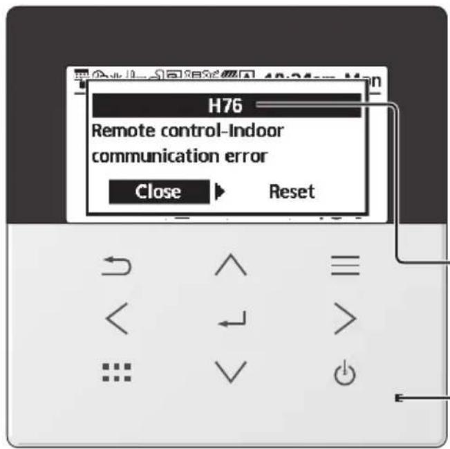
Below is a list of error codes that may appear on the display when there is some trouble with the system setting or operation.
When the display shows an error code as indicated below, contact the number registered in the Remote Controller or a nearest authorised installer.
All switches are disabled except < > and .
Error number
Blinking
| Error No. | Error explanation |
| H12 | Capacity mismatch |
| H15 | Compressor sensor error |
| H20 | Pump error |
| H21 | Water pressure error |
| H22 | Tank sensor 2 error |
| H23 | Refrigerant sensor error |
| H27 | Service valve error |
| H28 | Solar sensor error |
| H31 | Pool sensor error |
| H36 | Buffer tank sensor error |
| H38 | Brand mismatch error |
| H42 | Low pressure protection |
| H43 | Zone 1 sensor error |
| H44 | Zone 2 sensor error |
| H62 | Water flow error |
| H63 | Low pressure sensor error |
| H64 | High pressure sensor error |
| H65 | Deice water circulation error |
| H67 | External thermistor 1 error |
| H68 | External thermistor 2 error |
| H70 | Back-up heater OLP error |
| H72 | Tank sensor 1 error |
| H74 | PCB communication error |
| H75 | Low water temp protection |
| H76 | RC-1 & Indoor communication errorRC-1 & RC-2 communication error |
| H90 | Indoor-Outdoor communication error |
| H91 | Tank heater OLP error |
| H95 | Voltage connection error |
| H98 | High pressure protection |
| H99 | Indoor freeze prevention |
| Error No. | Error explanation |
| F12 | Pressure switch activated |
| F14 | Poor compressor rotation |
| F15 | Fan motor lock error |
| F16 | Current protection |
| F20 | Compressor overload protection |
| F22 | Transistor module overload protection |
| F23 | DC peak |
| F24 | Refrigerant cycle error |
| F25 * | 1,*2 Cool / heat cycle error |
| F27 | Pressure switch error |
| F29 | Low discharge super heat |
| F30 | Water outlet sensor 2 error |
| F32 | RC-1's internal thermostat errorRC-2's internal thermostat error |
| F34 | Indoor water heat exchanger leak |
| F35 | External meter communication error |
| F36 | Outdoor ambient sensor error |
| F37 | Water inlet sensor error |
| F40 | Outdoor discharge sensor error |
| F41 | Power factor correction error |
| F42 | Outdoor heat exchanger sensor error |
| F43 | Outdoor defrost sensor error |
| F45 | Water outlet sensor error |
| F46 | Current transformer disconnection |
| F48 | Evaporator outlet sensor error |
| F49 | Bypass outlet sensor error |
| F50 | Water inlet 2 sensor error |
| F51 | Economizer outlet sensor error |
| F52 | Bypass inlet sensor error |
| F95 * | 1,*2 Cooling high pressure error |
* Some error code may not be applicable to your model. Consult authorised dealer for clarification.
*1 The system is locked to operate without COOL mode. It can be unlocked only by authorised installers or our authorised service partners.
*2 Only displayed when COOL mode is unlocked (This means when COOL mode is available).
Information when connecting to Network Adaptor (Optional Accessories Part)

WARNING
Before use, check the safety around the Air-to-Water system. Confirm human and living objects at surrounding before operation.
Incorrect operation due to failure to follow instructions may cause harm and damage.

Confirm the below before operation (inside premises)
- Timer setting condition. Unpredictable on/off operation may cause serious injury or damage to human and living objects.
Confirm the below before and during operation (outside from premises)
- If is known someone in the premises, notify the person from outside of new operation setting prior executing. This is to avoid sudden shock to the person and any serious health breakdown duly from operation changed.
- Please do not use this appliance when infant, physical disability person or elderly who unable to operate the appliance by themselves in the premises.
- Check the setting and operation status frequently.
- Stop the operation when error code is displayed and consult an authorised dealer or specialist.
Please confirm before use
- The system may not usable when communication condition is bad. Please check "Operation Status" from the application display after operation. The following condition may happen in the remote operation.
- Cannot operate, operation time is not reflected.
- Air-to-Water operation is not reflected when operation is set outside of premises.
- It is recommended to lock the screen of the smart phone device to prevent miss-operation.
- Do not use other remote control, communication and operation device not specified by an authorised dealer or specialist.
- Use under the agreement of "Terms of Service" and "Handling of Personal Information" of Panasonic Smart Application.
- For extended non-use of Panasonic Smart Application, disconnect the network adaptor from the device.
Only for European Union and countries with recycling systems
These symbols on the products, packaging, and/or accompanying documents mean that used electrical and electronic products and batteries must not be mixed with general household waste.
For proper treatment, recovery and recycling of old products and used batteries, please take them to applicable collection points in accordance with your national legislation.
By disposing of them correctly, you will help to save valuable resources and prevent any potential negative effects on human health and the environment.
For more information about collection and recycling, please contact your local authority.
Penalties may be applicable for incorrect disposal of this waste, in accordance with national legislation.
For business users in the European Union and some other European countries
If you wish to discard electrical and electronic equipment, please contact your dealer or supplier for further information.
[Information on Disposal in other Countries outside the European Union]
These symbols are only valid in the European Union. If you wish to discard these items, please contact your local authority or dealer and ask for the correct method of disposal.

No pen
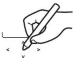

Without pen


Do not use a pen
Arrow keys

Without pen

No pen
Cursor buttons
Select item.

1.2 Holiday program
1.3 Silence program
1.4 Priority silence

Without pen
Enter key
No pen