MOTOTRBO R7 - Radio MOTOROLA - Free user manual and instructions
Find the device manual for free MOTOTRBO R7 MOTOROLA in PDF.

| Product Type | Professional two-way radio (portable) |
| Brand | Motorola Solutions |
| Model | MOTOTRBO R7 |
| Operating modes | Analog and digital (DMR) with conventional, Capacity Plus, Capacity Max, IP interconnect modes |
| Protection rating | IP66 (high-pressure water jets) and IP68 (immersion up to 2 meters for 2 hours) |
| Battery | Rechargeable lithium-ion, IMPRES compatible |
| Display | Color display with backlight (full keyboard model) / Indicator LED (no-keypad model) |
| Keypad | Available in full keypad or no-keypad version |
| Programmable buttons | Multiple buttons (P1, P2, side) with assignable functions (scan, emergency, etc.) |
| Wireless connectivity | Bluetooth, Wi-Fi (2.4/5 GHz), GNSS (GPS/GLONASS) |
| Emergency functions | Emergency alarm, fall alert, lone worker, silent mode |
| Audio | Front and rear noise-canceling microphone, built-in speaker, noise suppression, audio profiles |
| Audio recording | Valid call recording with built-in playback |
| Programming | Front panel programming (FPP) and over-the-air programming (OTAP) for remote updates |
| Cleaning and disinfection | Approved agents: 70% isopropyl alcohol, 70% ethanol, germicidal wipes (PDI, Lysol, Clorox) |
| Warranty | Motorola Solutions limited warranty (see manual for details) |
Frequently Asked Questions - MOTOTRBO R7 MOTOROLA
User questions about MOTOTRBO R7 MOTOROLA
0 question about this device. Answer the ones you know or ask your own.
Ask a new question about this device
Download the instructions for your Radio in PDF format for free! Find your manual MOTOTRBO R7 - MOTOROLA and take your electronic device back in hand. On this page are published all the documents necessary for the use of your device. MOTOTRBO R7 by MOTOROLA.
USER MANUAL MOTOTRBO R7 MOTOROLA
MOTOTRBO R7 Series Portable Two-Way Radios User Guide
Contents
List of Figures......11
List of Tables....12
Legal and Support....13
Intellectual Property and Regulatory Notices....13
Legal and Compliance Statements....14
Supplier's Declaration of Conformity.... 14
ISED WLAN Statement....15
Notice to Users (FCC).... 15
Notice to Users (ISED).... 15
Important Safety Information....15
Citizens Band License....16
Citizens Band Repeater Operation....16
25 kHz Land Mobile Band to 12.5 kHz Narrow Band Transition.... 16
Maritime Radio Use in the VHF Frequency Range.... 17
Special Channel Assignments.... 17
Operating Frequency Requirements....17
Declaration of Compliance for the Use of Distress and Safety Frequencies....20
Regulatory Compliance Information....20
Warranty and Service Support....21
Batteries and Chargers Warranty....21
The Workmanship Warranty....21
The Capacity Warranty....21
Limited Warranty.... 21
MOTOROLA SOLUTIONS COMMUNICATION PRODUCTS....21
I. WHAT THIS WARRANTY COVERS AND FOR HOW LONG: 21
II. GENERAL PROVISIONS....22
III. STATE LAW RIGHTS: 22
IV. HOW TO GET WARRANTY SERVICE....22
V. WHAT THIS WARRANTY DOES NOT COVER.... 22
VI. PATENT AND SOFTWARE PROVISIONS.... 23
VII. GOVERNING LAW....23
VIII. For Australia Only....23
Chapter 1: Read Me First....25
1.1 Software Version....26
1.2 Specifications....26
Chapter 2: Introduction....27
Chapter 3: Radio Care....29
3.1 Cleaning and Disinfecting Your Radio....29
3.2 Storing Your New Radio....30
Chapter 4: Radio Overview.... 31
4.1 Keypad Overview....34
4.2 Programmable Buttons.... 35
Chapter 5: System Overview.... 39
5.1 Capacity Max.... 39
5.2 Conventional Analog and Digital Modes....39
5.3 IP Site Connect....39
5.4 Capacity Plus.... 40
5.5 Direct Mode or Dual Capacity Direct Mode....40
Chapter 6: WAVE....42
6.1 WAVE OnCloud/OnPremise....42
6.1.1 Switching from Radio Mode to WAVE Mode....42
6.1.2 Switching from WAVE Mode to Radio Mode....42
Chapter 7: Getting Started....44
7.1 Charging the Battery....44
7.2 Attaching or Detaching the Battery....44
Attaching the Battery.... 44
Detaching the Battery....45
7.3 Attaching or Detaching the Antenna.... 45
Attaching the Antenna.... 45
Detaching the Antenna....45
7.4 Attaching the Universal Connector Cover.... 46
7.4 Attaching the Universal Connector Cover 46
7.5 Removing the Universal Connector Cover....46
7.6 Cleaning the Universal Connector Cover....46
7.7 Turning the Radio On or Off....47
Turning the Radio On....47
Turning the Radio Off....47
7.8 Holding Your Radio While Transmitting Audio....47
7.8 Holding Your Radio While Transmitting Audio....47
7.9 Adjusting the Volume.... 48
7.10 Inserting the Radio into the Carry Case....48
7.11 Removing the Radio from the Carry Case....48
Chapter 8: Home Screen Overview....49
8.1 Status Indicators....49
8.1.1 Status Icons....50
8.1.2 Bluetooth Device Icons....52
8.1.3 Call Icons....52
MN007848A01-AL Contents
8.1.4 Job Tickets Icons....53
8.1.5 Mini Notice Icons.... 53
8.1.6 LED Indications....54
8.2 Radio Control Widget....55
8.2.1 Lightbar Indicators....55
8.3 Notification Widget....56
8.3.1 Notification Widget Icons....56
8.4 Screen Saver....57
Chapter 9: Icon-Based Menu Overview....58
9.1 Icon-Based Menu Icons....58
9.2 Accessing Icon-Based Menu....59
Chapter 10: Basic Radio Operation....60
10.1 Registration....60
10.2 Site Overview....60
10.2.1 Site Trunking....61
10.2.2 Auto Roaming....61
10.2.3 Turning the Site Lock On....61
10.2.4 Turning the Site Lock Off....62
10.2.5 Enabling the Manual Site Search....62
10.2.6 Accessing Neighbor Sites List....62
10.3 Zone and Channel Selections....63
10.3.1 Selecting Zones....63
10.3.2 Selecting Zones Using Alias Search....63
10.3.3 Selecting Channels....63
10.3.4 Selecting Channels Using Direct Channel Dial....64
10.4 Responding to Notifications....64
10.5 Service and Support....64
10.5.1 Accessing Service Code for Full Keypad Model....64
10.5.2 Accessing Service Code for Non-Keypad Model....65
10.5.3 Viewing Service Contact....66
10.6 Accessing Action List....66
10.7 Accessing the Radio Information....67
10.8 Accessing Text Editor Options....67
Chapter 11: General Radio Settings....69
11.1 Talkaround....69
11.1.1 Toggling Between Repeater and Talkaround Mode....69
11.2 Setting Date and Time....69
11.2 Setting Date and Time....69
11.3 Setting Radio Tones and Alerts....70
11.4 Setting Power Levels....70
11.5 Adjusting Display Settings....71
11.6 Setting Squelch Levels....71
11.7 Keypad Lock Options....71
11.7.1 Locking or Unlocking the Keypad.... 71
11.8 Setting Languages....72
11.9 Setting the Global Navigation Satellite System....72
11.10 Setting LED Indicators....72
11.11 Password Lock....73
11.11.1 Accessing Radios with Password....73
11.11.2 Unlocking Radios in Locked State....73
11.11.3 Setting the Password Lock....74
11.11.4 Changing Passwords....74
11.12 Setting the Voice Announcement....74
11.13 Text-to-Speech....75
11.13.1 Setting the Text-to-Speech....75
11.14 Setting the Microphone Automatic Gain Control....75
11.15 Setting the Microphone Distortion....76
11.16 Setting the Noise Suppress....76
11.17 Setting the Audio Ambience.... 76
11.18 Setting Audio Profiles....77
11.19 Setting the Text Entry....77
11.20 Voice Operating Transmission....78
11.20.1 Setting the Voice Operating Transmission....78
11.21 Selecting Cable Type....78
Chapter 12: Types of Radio Calls....80
12.1 Making Calls on the Radio....81
12.2 Making Calls with Contact List....82
12.3 Making Calls with Manual Dial....82
12.4 Making Calls with Programmable Number Keys....83
12.5 Receiving and Responding to Calls on the Radio....83
12.6 Accepting or Declining Private Calls....84
Accepting Private Calls....84
Declining Private Calls 84
Chapter 13: Phone Calls....85
13.1 Making Phone Calls....85
13.2 Making Phone Calls with Contact List....85
13.3 Making Phone Calls with Manual Dial....86
13.4 Dual Tone Multi Frequency....86
13.4.1 Initiating the DTMF Tone....86
13.5 Receiving and Responding to Phone Calls....87
Chapter 14: Audio Recording....88
14.1 Accessing Audio Playback....88
Chapter 15: Switching Audio Route between Internal Radio Speaker and Wired Accessory....90
Chapter 16: Connectivity....91
16.1 Wi-Fi Operation....91
16.1.1 Turning the Wi-Fi On or Off....91
16.1.2 Turning Wi-Fi On Remotely Using a Designated Radio....91
16.1.3 Turning Wi-Fi Off Remotely Using a Designated Radio....92
16.1.4 Network Access....92
16.1.4.1 Connecting to a Network Access Point....92
16.1.4.2 Checking Wi-Fi Connection Status....93
16.1.4.3 Refreshing Network Lists....93
16.1.4.4 Adding a Network....94
16.1.4.5 Viewing Details of Network Access Points 94
16.1.4.6 Removing Network Access Points....95
16.1.5 Accessing Enterprise Wi-Fi Network....95
16.2 Bluetooth® 95
16.2.1 Turning the Bluetooth On or Off....96
Turning Bluetooth On....96
Turning Bluetooth Off....96
16.2.2 Connecting to Bluetooth Devices....96
16.2.3 Disconnecting from Bluetooth Devices....98
16.2.4 Switching Audio Route between Internal Radio Speaker and Bluetooth Device....98
16.2.5 Viewing Device Details....98
16.2.6 Editing Device Names....98
16.2.7 Deleting Device....99
16.2.8 Bluetooth Profiles 99
Chapter 17: Emergency Operation....100
17.1 Sending Emergency Alarms....101
17.2 Sending Emergency Alarms with Call.... 101
17.3 Sending Emergency Alarms with Voice to Follow.... 101
17.4 Responding to Emergency Alarms....102
17.5 Responding to Emergency Alarms with Call....103
17.6 Exiting Emergency Mode.... 103
Chapter 18: Fall Alert.... 105
18.1 Turning the Fall Alert Feature On or Off.... 105
Turning the Fall Alert Feature On....105
Turning the Fall Alert Feature Off....105
Chapter 19: Lone Worker....106
Chapter 20: Call Alert Operation.... 107
20.1 Making Call Alerts.... 107
20.2 Responding to Call Alerts....107
Chapter 21: Call Log Features....108
21.1 Viewing Recent Calls....108
21.2 Storing Aliases or IDs from the Call List.... 108
21.3 Deleting Calls from the Call List.... 109
21.4 Viewing Details from the Call List.... 109
Chapter 22: Call Queue....110
22.1 Receiving Call Queues....110
Chapter 23: Priority Call....111
23.1 Switching the Priority Call Level.... 111
Chapter 24: Contacts Settings....112
24.1 Adding New Contacts....112
24.2 Setting Default Contacts....112
24.3 Assigning Entries to Programmable Number Keys....112
24.4 Removing Associations Between Entries and Programmable Number Keys....113
Chapter 25: Call Indicator Settings....114
25.1 Activating or Deactivating Call Ringers....114
Activating Call Ringers....114
Deactivating Call Ringers....114
25.2 Assigning Ring Styles....115
25.3 Ring Alert Type....115
25.3.1 Selecting Ring Alert Types.... 115
25.4 Escalating Alarm Tone Volume.... 115
Chapter 26: Privacy....117
26.1 Setting Privacy.... 117
26.2 Privacy-Enabled Calls....117
Chapter 27: Scan....119
27.1 Turning the Scan On.... 120
27.2 Turning the Scan Off....120
27.3 Scan Talkback....120
27.4 Nuisance Channels....121
27.4.1 Deleting Nuisance Channels....121
27.4.2 Restoring Nuisance Channels....121
27.5 Vote Scan....121
27.5 Vote Scan....121
27.6 Priority Monitor....122
27.7 Receive Group List....122
27.8 Scan Lists....122
MN007848A01-AL Contents
27.8.1 Accessing Scan List.... 123
27.9 Flexible Receive List 124
27.9.1 Turning the Flexible Receive List On....124
27.9.2 Turning the Flexible Receive List Off.... 124
27.9.3 Adding New Entries to the Flexible Receive List....125
27.9.4 Deleting Entries from the Flexible Receive List....125
27.10 Multi-Talkgroup Affiliation....125
27.10.1 Adding the Talkgroup Affiliation.... 125
27.10.2 Removing the Talkgroup Affiliation.... 126
Chapter 28: Security....127
28.1 Stunning Radios....127
28.2 Reviving Radios....128
28.3 Radio Kill.... 128
Chapter 29: Indoor Location....129
29.1 Turning the Indoor Location On.... 129
29.2 Turning the Indoor Location Off.... 129
29.3 Accessing Indoor Location Beacons Information....130
Chapter 30: Job Tickets....131
30.1 Accessing the Job Ticket Folder.... 131
30.2 Logging In the Remote Server.... 132
30.3 Creating Job Tickets.... 132
30.4 Sending Job Tickets by Using Job Tickets Templates.... 132
30.5 Receiving and Responding to Job Tickets....133
30.6 Deleting Job Tickets....134
Chapter 31: Text Messaging.... 135
31.1 Viewing Text Messages.... 135
31.2 Composing Text Messages.... 135
31.3 Sending Text Messages.... 136
31.4 Responding to Text Messages.... 137
31.5 Forwarding Text Messages....137
31.6 Deleting Text Messages....138
31.7 Setting Text Message Alert Tones.... 138
Chapter 32: Status Message....139
32.1 Viewing Status Messages....139
32.2 Sending Status Messages.... 139
32.3 Replying Status Messages....140
32.4 Initiating Private Call 140
32.5 Deleting Status Messages.... 140
Chapter 33: Analog Status Update.... 141
33.1 Sending Status Updates to Predefined Contacts.... 141
33.2 Viewing 5-Tone Status Details....141
33.3 Editing 5-Tone Status Details....142
34.1 Sending MDC Encode Messages to Dispatchers.... 143
36.1 Editing the Caller Alias.... 145
36.2 Viewing the Caller Aliases List.... 145
36.3 Initiating Private Calls From the Caller Aliases List.... 145
37.1 Making DGNA Calls.... 146
37.2 Making Non-DGNA Calls....146
37.3 Receiving and Responding to DGNA Calls....147
38.1 Entering the Front Panel Programming....148
39.1 Muting the Home Channel Reminder.... 149
39.2 Setting New Home Channels....149
40.1 Monitoring Channels.... 150
40.2 Permanent Monitor....150
40.2.1 Setting the Permanent Monitor....150
41.1 Initiating the Remote Monitor....152
42.1 Sending Radio Checks.... 153
43.1 Turning the Mute Mode On.... 154
43.2 Setting the Mute Mode Timer....154
43.3 Exiting the Mute Mode.... 154
44.1 Viewing RSSI Values....156
45.1 Setting the Response Inhibit.... 157
46.1 Accessing Rental Timer Information....158
46.2 Rental Expiry Reminder.... 158
Chapter 34: Analog Message Encode.... 143
Chapter 35: Auto-Range Transponder System....144
Chapter 36: Dynamic Caller Alias....145
Chapter 37: Dynamic Group Number Assignment....146
Chapter 38: Front Panel Programming....148
Chapter 39: Home Channel Reminder....149
Chapter 40: Monitor Feature.... 150
Chapter 41: Remote Monitor....151
Chapter 42: Radio Check....153
Chapter 43: Mute Mode....154
Chapter 44: Received Signal Strength Indicator.... 156
Chapter 45: Response Inhibit....157
Chapter 46: Rental Timer....158
MN007848A01-AL Contents
46.3 Extending the Rental Period....159
Chapter 47: Transmit Inhibit....160
47.1 Enabling or Disabling the Transmit Inhibit.... 160
Chapter 48: Call Preemption ...... 161
Chapter 49: Voice Interrupt.... 162
49.1 Enabling the Voice Interrupt....162
49.2 Initiating Transmit Interrupt....162
Chapter 50: Over-the-Air Programming.... 163
Chapter 51: Authorized Accessories List.... 164
List of Figures
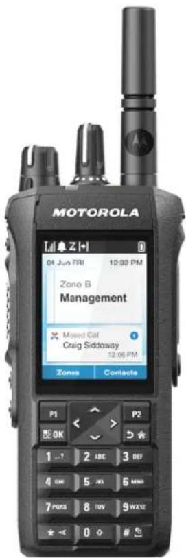
Figure 1: R7....27
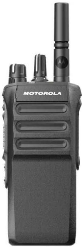
Figure 2: R7, R7a 27
Figure 3: Keypad Overview....34
Figure 4: Action List Overview....66
List of Tables
Table 1: VHF Marine Channel List.... 18
Table 2: Special Notations.... 25
Table 3: The Feature Access and Indications of Different Radio Model....27
Table 4: IP Specification....29
Table 5: Full Keypad Model Overview....31
Table 6: Non-Keypad Model Overview....32
Table 7: Keypad Overview.... 34
Table 8: Assignable Radio Functions.... 35
Table 9: Home Screen Overview....49
Table 10: Bluetooth Device Icons.... 52
Table 11: Call Icons....52
Table 12: Job Ticket Icons....53
Table 13: Mini Notice Icons....54
Table 14: LED Indications....54
Table 15: Notification Widget Overview.... 56
Table 16: Types of Site Search....61
Table 17: Number of Supported Zones and Channels....63
Table 18: Action List Overview....66
Table 19: Types of Radio Calls....80
Table 20: Bluetooth Profiles....99
Table 21: Emergency Modes....100
Table 22: Privacy Types and Settings....117
Table 23: Scan Methods....119
Table 24: Scan Talkback Type.... 120
Table 25: Text Message Types and the Character Limits.... 135
Table 26: Auto-Range Transponder System Indications....144
Table 27: Hot Mic Sources....151
Legal and Support
Intellectual Property and Regulatory Notices
Copyrights
The Motorola Solutions products described in this document may include copyrighted Motorola Solutions computer programs. Laws in the United States and other countries preserve for Motorola Solutions certain exclusive rights for copyrighted computer programs. Accordingly, any copyrighted Motorola Solutions computer programs contained in the Motorola Solutions products described in this document may not be copied or reproduced in any manner without the express written permission of Motorola Solutions.
No part of this document may be reproduced, transmitted, stored in a retrieval system, or translated into any language or computer language, in any form or by any means, without the prior written permission of Motorola Solutions, Inc.
Trademarks
MOTOROLA, MOTO, MOTOROLA SOLUTIONS, and the Stylized M Logo are trademarks or registered trademarks of Motorola Trademark Holdings, LLC and are used under license. All other trademarks are the property of their respective owners.
License Rights
The purchase of Motorola Solutions products shall not be deemed to grant either directly or by implication, estoppel or otherwise, any license under the copyrights, patents or patent applications of Motorola Solutions, except for the normal nonexclusive, royalty-free license to use that arises by operation of law in the sale of a product.
Open Source Content
This product may contain Open Source software used under license. Refer to the product installation media for full Open Source Legal Notices and Attribution content.
European Union (EU) and United Kingdom (UK) Waste of Electrical and Electronic Equipment (WEEE) Directive

The European Union's WEEE directive and the UK's WEEE regulation require that products sold into EU countries and the UK must have the crossed-out wheelie bin label on the product (or the package in some cases). As defined by the WEEE directive, this crossed-out wheelie bin label means that customers and end users in EU and UK countries should not dispose of electronic and electrical equipment or accessories in household waste.
Customers or end users in EU and UK countries should contact their local equipment supplier representative or service center for information about the waste collection system in their country.
Disclaimer
Please note that certain features, facilities, and capabilities described in this document may not be applicable to or licensed for use on a specific system, or may be dependent upon the characteristics of a specific mobile subscriber unit or configuration of certain parameters. Please refer to your Motorola Solutions contact for further information.
© 2025 Motorola Solutions, Inc. All Rights Reserved
Legal and Compliance Statements
Supplier's Declaration of Conformity
Supplier's Declaration of Conformity
Per FCC CFR 47 Part 2 Section 2.1077(a)

Responsible Party
Name: Motorola Solutions, Inc.
Address: 2000 Progress Pkwy, Schaumburg, IL. 60196
Phone Number: 1-800-927-2744
Hereby declares that the product:
Model Name: R7
conforms to the following regulations:
FCC Part 15, subpart B, section 15.107(a), 15.107(d), and section 15.109(a)
Class B Digital Device
As a personal computer peripheral, this device complies with Part 15 of the FCC Rules. Operation is subject to the following two conditions:
-
This device may not cause harmful interference, and
-
This device must accept any interference received, including interference that may cause undesired operation.

NOTE:
This equipment has been tested and found to comply with the limits for a Class B digital device, pursuant to part 15 of the FCC Rules. These limits are designed to provide reasonable protection against harmful interference in a residential installation. This equipment generates, uses and can radiate radio frequency energy and, if not installed and used in accordance with the instructions, may cause harmful interference to radio communications. However, there is no guarantee that interference will not occur in a particular installation.
If this equipment does cause harmful interference to radio or television reception, which can be determined by turning the equipment off and on, the user is encouraged to try to correct the interference by one or more of the following measures:
● Reorient or relocate the receiving antenna.
- Increase the separation between the equipment and receiver.
- Connect the equipment into an outlet on a circuit different from that to which the receiver is connected.
- Consult the dealer or an experienced radio or TV technician for help.
For country code selection usage (WLAN devices)

NOTE: The country code selection is for non-US model only and is not available to all US models. Per FCC regulation, all Wi-Fi products marketed in the US must be fixed to US operation channels only.
ISED WLAN Statement

CAUTION:
- The device for operation in the band 5150–5250 MHz is only for indoor use to reduce the potential for harmful interference to co-channel mobile satellite systems;
- For devices with detachable antenna(s), the maximum antenna gain permitted for devices in the bands 5250–5350 MHz and 5470–5725 MHz shall be such that the equipment still complies with the e.i.r.p. limit;
- For devices with detachable antenna(s), the maximum antenna gain permitted for devices in the band 5725–5850 MHz shall be such that the equipment still complies with the e.i.r.p. limits as appropriate; and
- Where applicable, antenna type(s), antenna model(s), and worst-case tilt angle(s) necessary to remain compliant with the e.i.r.p. elevation mask requirement set forth in section 6.2.2.3 shall be clearly indicated.
Notice to Users (FCC)
This device complies with Part 15 of the FCC rules per the following conditions:
- This device may not cause harmful interference.
- This device must accept any interference received, including interference that may cause undesired operation.
- Changes or modifications made to this device, not expressly approved by Motorola Solutions, could void the authority of the user to operate this equipment.
Notice to Users (ISED)
The operation of your Motorola Solutions radio is subject to the Radiocommunications Act and must comply with rules and regulations of the Federal Government's department of Innovation, Science, and Economic Development Canada (ISED). ISED requires that all operators using Private Land Mobile frequencies obtain a radio license before operating their equipment.
Important Safety Information
RF Energy Exposure and Product Safety Guide for Portable Two-Way Radios

CAUTION:
This radio is restricted to Occupational use only. Before using the radio, read the RF Energy Exposure and Product Safety Guide that comes with the radio. This guide contains operating instructions for safe usage, RF energy awareness, and control for compliance with applicable standards and regulations.
Any modification to this device, not expressly authorized by Motorola Solutions, may void the user's authority to operate this device.
Under Innovation, Science, and Economic Development Canada (ISED) regulations, this radio transmitter may only operate using an antenna of a type and maximum (or lesser) gain approved for the transmitter by ISED. To reduce potential radio interference to other users, the antenna type and its gain should be so chosen that the equivalent isotropically radiated power (e.i.r.p.) is not more than that necessary for successful communication.
This radio transmitter has been approved by Innovation, Science, and Economic Development Canada (ISED) to operate with Motorola Solutions-approved antenna with the maximum permissible gain and required antenna impedance for each antenna type indicated. Antenna types not included in this list, having a gain greater than the maximum gain indicated for that type, are strictly prohibited for use with this device.
Citizens Band License
The use of the Citizens Band radio service is licensed in Australia by the Australian Communications and Media Authority (ACMA) Radiocommunications (Citizens Band Radio Stations) Class Licence and in New Zealand by the Ministry of Economic Development New Zealand (MED) General User Radio Licence (GURL) for Citizens Band Radio, and operation is subject to the conditions contained in those licences.
In Australia, a Citizens Band transmitter shall not be operated on UHF emergency channels 5 and 35 and no voice transmissions are permitted on data (telemetry/telecommand) channels 22 and 23, except in an emergency. The radio that complies to this Standard will inhibit voice operation on channels 22 and 23. In the event that additional telemetry/telecommand channels are approved by the ACMA, these channels shall be added to those currently listed where voice transmission is inhibited.
Always listen on a channel (or observe a channel-busy indicator) to ensure it is not already being used before transmitting.
Citizens Band Repeater Operation
A repeater is a station established at a fixed location that receives radio signals from one Citizens Band station and automatically retransmits the signal to another station using the corresponding output channel. UHF Citizens Band repeaters can be found in all states and enable the range of vehicle to vehicle communications to be significantly increased. Avoid operating on locally used repeater input channels (which are in the range of channels 31 to 38, and channels 71 to 78 when they are authorized) or locally used repeater receiving channels (which will be in the range channels 1 to 8, and channels 41 to 48 when they are authorized), unless long-distance communication via the repeater facility is specifically required.

NOTE: In Australia, channel 11 is the customary calling channel for establishing communication and channel 40 is the customary road vehicle channel.
25 kHz Land Mobile Band to 12.5 kHz Narrow Band Transition
The existing use of 25 kHz analogue land mobile channels is to cease by 1 November 2015. This period is in accordance with the minimum period (five years) specified in the Radio Regulations for giving notice of revocation of a licence of an undefined duration.
Land mobile frequency bands with an offset channel plan (E, EN, and ENX bands) require a different treatment to manage the introduction of digital land mobile radio (due to potential adjacent channel interference risks). The following items apply to these bands:
- Users of E band (25 kHz channels) wanting to transition to digital prior 1 November 2015, can migrate to the EE band (also in the VHF range) or any other band open for digital land mobile radio licensing.
- E band users wanting to continue operating analogue services after the five year transition period can migrate to 12.5 kHz analogue channels in the EN band (also in the VHF range) or any other band open for narrow band analogue land mobile radio.
- Introduction of digital land mobile radio in the EN and ENX bands prior to 1 November 2015 will be considered on a case by case basis. Licensing of digital land mobile radio in these bands will be possible
in areas where E band users have vacated the band, or when rigorous engineering analysis guarantees no risk of interference to other band users.
For the list of currently authorized channels, please refer to the following websites:
- https://www.acma.gov.au/licences/citizen-band-radio-stations-class-licence (Australia)
- https://www.rsm.govt.nz/licensing/frequencies-for-anyone/citizen-band-radio-gurl/ (New Zealand)
Maritime Radio Use in the VHF Frequency Range
This section is only applicable for United States and Canada only.
Special Channel Assignments
Emergency Channel
If you are in imminent and grave danger at sea and require emergency assistance, use VHF Channel 16 to send a distress call to nearby vessels and the United States Coast Guard. Transmit the following information, in this order:
- "MAYDAY, MAYDAY, MAYDAY."
- "THIS IS ____, CALL SIGN ____." State the name of the vessel in distress 3 times, followed by the call sign or other identification of the vessel, stated 3 times.
- Repeat "MAYDAY" and the name of the vessel.
- "WE ARE LOCATED AT ____." State the position of the vessel in distress, using any information that will help responders to locate you, e.g.:
• latitude and longitude
- bearing (state whether you are using true or magnetic north)
• distance to a well-known landmark
- vessel course, speed or destination
- State the nature of the distress.
- Specify what kind of assistance you need.
- State the number of persons on board and the number needing medical attention, if any.
- Mention any other information that would be helpful to responders, such as type of vessel, vessel length and/or tonnage, hull color, etc.
- "OVER."
- Wait for a response.
- If you do not receive an immediate response, remain by the radio and repeat the transmission at intervals until you receive a response. Be prepared to follow any instructions given to you.
Non-Commercial Call Channel
For non-commercial transmissions, such as fishing reports, rendezvous arrangements, repair scheduling, or berthing information, use VHF Channel 9.
Operating Frequency Requirements
A radio designated for shipboard use must comply with Federal Communications Commission Rule Part 80 as follows:
- on ships subject to Part II of Title III of the Communications Act, the radio must be capable of operating on the 156.800 MHz frequency.
● on ships subject to the Safety Convention, the radio must be capable of operating:
in the simplex mode on the ship station transmitting frequencies specified in the 156.025–157.425 MHz frequency band, and
- in the semiduplex mode on the two frequency channels specified in the table below.

NOTE: Additional information about operating requirements in the Maritime Services can be obtained from the full text of FCC Rule Part 80 and from the US Coast Guard.
Table 1: VHF Marine Channel List
| Channel Number Frequency (MHz) | |
| Transmit Receive | |
| 1 156.050 160.650 | |
| 2 156.100 160.700 | |
| *1 | 156.150 160.750 |
| 4 156.200 160.800 | |
| 5 156.250 160.850 | |
| 6 156.300 - | |
| 7 156.350 160.950 | |
| 8 156.400 - | |
| 9 156.450 156.450 | |
| 10 156.500 156.500 | |
| 11 156.550 156.550 | |
| 12 156.600 156.600 | |
| 13**2 | 156.650 156.650 |
| 14 156.700 156.700 | |
| 15**2 | 156.750 156.750 |
| 16 156.800 156.800 | |
| 17**2 | 156.850 156.850 |
| 18 156.900 161.500 | |
| 19 156.950 161.550 | |
| 20 157.000 161.600 | |
| *1 | 157.050 161.650 |
| 22 157.100 161.700 | |
| *1 | 157.150 161.750 |
| 24 157.200 161.800 | |
| 25 157.250 161.850 | |
| 26 157.300 161.900 | |
| 27 157.350 161.950 | |
| 28 157.400 162.000 | |
| 60 156.025 160.625 | |
| *1 | 156.075 160.675 |
| 62 156.125 160.725 | |
| 63 156.175 160.775 | |
| *1 | 156.225 160.825 |
| 65 156.275 160.875 | |
| 66 156.325 160.925 | |
| 67**2 | 156.375 156.375 |
| 68 156.425 156.425 | |
| 69 156.475 156.475 | |
| 71 156.575 156.575 | |
| 72 156.625 - | |
| 73 156.675 156.675 | |
| 74 156.725 156.725 | |
| 75 *** | 3 ***3 |
| 76 *** | 3 ***3 |
| 77**2 | 156.875 - |
| 78 156.925 161.525 | |
| 79 156.975 161.575 | |
| 80 157.025 161.625 | |
| *1 | 157.075 161.675 |
| *1 | 157.125 161.725 |
| *1 | 157.175 161.775 |
| 84 157.225 161.825 | |
| 85 157.275 161.875 | |
| 86 157.325 161.925 | |
| 87 157.375 161.975 | |
| 88 157.425 162.025 | |

NOTE: A – in the Receive column indicates that the channel is transmit only.
Declaration of Compliance for the Use of Distress and Safety Frequencies
The radio equipment does not employ a modulation other than the internationally adopted modulation for maritime use when it operates on the distress and safety frequencies specified in RSS-182 Section 5.4.
Regulatory Compliance Information
EAC
China
The CMIIT ID is shown on the radio equipment identification label.
India
This product(s) conforms to the relevant Essential Requirements of TEC, Department of Telecommunications, Ministry of Communications, Govt. of India, New Delhi-110001.
| AZH06RDC9RA1AN AZH06RDC9RA2AN AZH06RDC9VA1AN |
| AZH06RDC9VA2AN AZH06RDC9WA1AN AZH06RDC9WA2AN |
| AZH06RDN9RA1AN AZH06RDN9RA2AN AZH06RDN9WA1AN |
| AZH06RDN9WA2AN AZH06JDC9RA1AN AZH06JDC9RA2AN |
| AZH06JDC9VA1AN AZH06JDC9VA2AN AZH06JDC9WA1AN |
| AZH06JDC9WA2AN AZH06JDN9RA1AN AZH06JDN9RA2AN |
| AZH06JDN9WA1AN AZH06JDN9WA2AN AZH06NDN9RA1AN |
| AZH06NDN9RA2AN AZH06UCC9VB1AN AZH06UCC9VB2AN |
| AZH06UCN9RB1AN AZH06UCN9RB2AN - |
Singapore
This IMDA label is applicable to these products:
| AZH06JDN9RA1AN AZH06JDN9RA2AN AZH06JDC9RA1AN |
| AZH06JDC9RA2AN AZH06JDC9VA1AN AZH06JDC9VA2AN |
| AZH06RDN9RA1AN AZH06RDN9RA2AN AZH06RDC9RA1AN |
| AZH06RDC9RA2AN AZH06RDC9VA1AN AZH06RDC9VA2AN |
Complies with
IMDA Standards
DB01909
Warranty and Service Support
Batteries and Chargers Warranty
The Workmanship Warranty
The workmanship warranty guarantees against defects in workmanship under normal use and service.
| All MOTOTRBO Batteries Please refer to the warranty statement of your region. | |
| IMPRES Chargers (Single-Unit and Multi-Unit, with Display) | 12 Months |
The Capacity Warranty
The capacity warranty guarantees 80% of the rated capacity for the warranty duration. Please refer to the warranty statement for your region.
Limited Warranty
MOTOROLA SOLUTIONS COMMUNICATION PRODUCTS
I. WHAT THIS WARRANTY COVERS AND FOR HOW LONG:
Motorola Solutions, Inc. ("Motorola Solutions") warrants the Motorola Solutions manufactured Communication Products listed below ("Product") against defects in material and workmanship under normal use and service for a period of time from the date of purchase as scheduled below:
| Portable Radios Please refer to the warranty statement of your region. | |
| Product Accessories One (1) Year | |
Motorola Solutions, at its option, will at no charge either repair the Product (with new or reconditioned parts), replace it (with a new or reconditioned Product), or refund the purchase price of the Product during the warranty period provided it is returned in accordance with the terms of this warranty. Replaced parts or boards are warranted for the balance of the original applicable warranty period. All replaced parts of Product shall become the property of Motorola Solutions.
This express limited warranty is extended by Motorola Solutions to the original end user purchaser only and is not assignable or transferable to any other party. This is the complete warranty for the Product manufactured by Motorola Solutions. Motorola Solutions assumes no obligations or liability for additions or modifications to this warranty unless made in writing and signed by an officer of Motorola Solutions.
Unless made in a separate agreement between Motorola Solutions and the original end user purchaser, Motorola Solutions does not warrant the installation, maintenance or service of the Product.
Motorola Solutions cannot be responsible in any way for any ancillary equipment not furnished by Motorola Solutions which is attached to or used in connection with the Product, or for operation of the Product with any ancillary equipment, and all such equipment is expressly excluded from this warranty. Because each
system which may use the Product is unique, Motorola Solutions disclaims liability for range, coverage, or operation of the system as a whole under this warranty.
II. GENERAL PROVISIONS
This warranty sets forth the full extent of Motorola Solutions responsibilities regarding the Product. Repair, replacement or refund of the purchase price, at Motorola Solutions option, is the exclusive remedy. THIS WARRANTY IS GIVEN IN LIEU OF ALL OTHER EXPRESS WARRANTIES. IMPLIED WARRANTIES, INCLUDING WITHOUT LIMITATION, IMPLIED WARRANTIES OF MERCHANTABILITY AND FITNESS FOR A PARTICULAR PURPOSE, ARE LIMITED TO THE DURATION OF THIS LIMITED WARRANTY. IN NO EVENT SHALL MOTOROLA SOLUTIONS BE LIABLE FOR DAMAGES IN EXCESS OF THE PURCHASE PRICE OF THE PRODUCT, FOR ANY LOSS OF USE, LOSS OF TIME, INCONVENIENCE, COMMERCIAL LOSS, LOST PROFITS OR SAVINGS OR OTHER INCIDENTAL, SPECIAL OR CONSEQUENTIAL DAMAGES ARISING OUT OF THE USE OR INABILITY TO USE SUCH PRODUCT, TO THE FULL EXTENT SUCH MAY BE DISCLAIMED BY LAW.
III. STATE LAW RIGHTS:
SOME STATES DO NOT ALLOW THE EXCLUSION OR LIMITATION OF INCIDENTAL OR CONSEQUENTIAL DAMAGES OR LIMITATION ON HOW LONG AN IMPLIED WARRANTY LASTS, SO THE ABOVE LIMITATION OR EXCLUSIONS MAY NOT APPLY.
This warranty gives specific legal rights, and there may be other rights which may vary from state to state.
IV. HOW TO GET WARRANTY SERVICE
You must provide proof of purchase (bearing the date of purchase and Product item serial number) in order to receive warranty service and, also, deliver or send the Product item, transportation and insurance prepaid, to an authorized warranty service location. Warranty service will be provided by Motorola Solutions through one of its authorized warranty service locations. If you first contact the company which sold you the Product (for example, dealer or communication service provider), it can facilitate your obtaining warranty service. You can also call Motorola Solutions at 1-800-927-2744.
V. WHAT THIS WARRANTY DOES NOT COVER
- Defects or damage resulting from use of the Product in other than its normal and customary manner.
- Defects or damage from misuse, accident, water, or neglect.
- Defects or damage from improper testing, operation, maintenance, installation, alteration, modification, or adjustment.
- Breakage or damage to antennas unless caused directly by defects in material workmanship.
- A Product subjected to unauthorized Product modifications, disassembles or repairs (including, without limitation, the addition to the Product of non-Motorola Solutions supplied equipment) which adversely affect performance of the Product or interfere with Motorola Solutions normal warranty inspection and testing of the Product to verify any warranty claim.
- Product which has had the serial number removed or made illegible.
- Rechargeable batteries if any of the seals on the battery enclosure of cells are broken or show evidence of tampering.
- Rechargeable batteries if the damage or defect is caused by charging or using the battery in equipment or service other than the Product for which it is specified.
-
Freight costs to the repair depot.
-
A Product which, due to illegal or unauthorized alteration of the software/firmware in the Product, does not function in accordance with Motorola Solutions published specifications or the FCC certification labeling in effect for the Product at the time the Product was initially distributed from Motorola Solutions.
- Scratches or other cosmetic damage to Product surfaces that does not affect the operation of the Product.
- Normal and customary wear and tear.
VI. PATENT AND SOFTWARE PROVISIONS
Motorola Solutions will defend, at its own expense, any suit brought against the end user purchaser to the extent that it is based on a claim that the Product or parts infringe a United States patent, and Motorola Solutions will pay those costs and damages finally awarded against the end user purchaser in any such suit which are attributable to any such claim, but such defense and payments are conditioned on the following:
- Motorola Solutions will be notified promptly in writing by such purchaser of any notice of such claim,
- Motorola Solutions will have sole control of the defense of such suit and all negotiations for its settlement or compromise, and
- Should the Product or parts become, or in Motorola Solutions opinion be likely to become, the subject of a claim of infringement of a United States patent, that such purchaser will permit Motorola Solutions, at its option and expense, either to procure for such purchaser the right to continue using the Product or parts or to replace or modify the same so that it becomes non-infringing or to grant such purchaser a credit for the Product or parts as depreciated and accept its return. The depreciation will be an equal amount per year over the lifetime of the Product or parts as established by Motorola Solutions.
Motorola Solutions will have no liability with respect to any claim of patent infringement which is based upon the combination of the Product or parts furnished hereunder with software, apparatus or devices not furnished by Motorola Solutions, nor will Motorola Solutions have any liability for the use of ancillary equipment or software not furnished by Motorola Solutions which is attached to or used in connection with the Product. The foregoing states the entire liability of Motorola Solutions with respect to infringement of patents by the Product or any parts thereof.
Laws in the United States and other countries preserve for Motorola Solutions certain exclusive rights for copyrighted Motorola Solutions software such as the exclusive rights to reproduce in copies and distribute copies of such Motorola Solutions software. Motorola Solutions software may be used in only the Product in which the software was originally embodied and such software in such Product may not be replaced, copied, distributed, modified in any way, or used to produce any derivative thereof. No other use including, without limitation, alteration, modification, reproduction, distribution, or reverse engineering of such Motorola Solutions software or exercise of rights in such Motorola Solutions software is permitted. No license is granted by implication, estoppel or otherwise under Motorola Solutions patent rights or copyrights.
VII. GOVERNING LAW
This Warranty is governed by the laws of the State of Illinois, U.S.A.
VIII. For Australia Only
This warranty is given by Motorola Solutions Australia Pty Limited (ABN 16 004 742 312) of Tally Ho Business Park, 10 Wesley Court. Burwood East, Victoria.
Our goods come with guarantees that cannot be excluded under the Australia Consumer Law. You are entitled to a replacement or refund for a major failure and compensation for any other reasonably foreseeable loss or damage. You are also entitled to have the goods repaired or replaced if the goods fail to be of acceptable quality and the failure does not amount to a major failure.
Motorola Solutions Australia's limited warranty above is in addition to any rights and remedies you may have under the Australian Consumer Law. If you have any queries, please call Motorola Solutions Australia at 1800
MN007848A01-AL Legal and Support
457 439. You may also visit our website: http://www.motorolasolutions.com/XA-EN/Pages/Contact_Us for the most updated warranty terms.
Chapter 1
Read Me First
This user guide covers the basic operations of the radio models offered in your region.
Notations Used in This Manual
Throughout the text in this publication, you notice the use of Warning, Caution, and Notice. These notations are used to emphasize that safety hazards exist, and the care that must be taken or observed.

WARNING: An operational procedure, practice, or condition, and so on, which may result in injury or death if not carefully observed.

CAUTION: An operational procedure, practice, or condition, and so on, which may result in damage to the equipment if not carefully observed.

NOTE: An operational procedure, practice, or condition, and so on, which is essential to emphasize.
Special Notations
The following special notations are used throughout the text to highlight certain information or items:
Table 2: Special Notations
| Example Description | |
| Menu key or PTT button | Bold words indicate a name of a key, button, or soft menu item. |
| Your radio shows Bluetooth On. | Typewriter words indicate the MMI strings or messages displayed on your radio. |
| The courier, bold, italic, and angle brackets indicate user input. | |
| Setup → Tone → All Tones | Bold words with the arrow in between indicate the navigation structure in the menu items. |
Feature and Service Availability

NOTE:
Not all features in the manual are available in your radio. Some features vary by geographical regions. Your dealer or administrator may also have customized your radio for your specific needs. Contact your dealer or administrator for more information.
You can consult your dealer or system administrator about the following:
- What are the functions of each button?
- Which optional accessories may suit your needs?
- What are the best radio usage practices for effective communication?
- What maintenance procedures promote longer radio life?
MN007848A01-AL
Chapter 1: Read Me First
1.1
Software Version
All the features described in the following sections are supported by the software version TRBO2025.02_FW_R02.25.02.1000 and onward.
Contact your dealer or administrator for more information.
1.2
Specifications
For more information about your radio specifications, refer to the data sheet of your radio model at motorolasolutions.com/r7-radio.
Chapter 2
Introduction
This user guide is explained as per the highest tier model offered to the region.
Your radio can be programmed using radio programming softwares such as Customer Programming Software (CPS) and Radio Management (RM).
The following table describes ways to access features for different radio models. You receive different indications depending on the radio model.
Table 3: The Feature Access and Indications of Different Radio Model
| Full Keypad Non-Keypad | ||
| Radio Model | Figure 1: R7 Figure 2: R7, R7a | |
 |  | |
| Feature Access | ● Menu4● Action List● Programmable Button | Programmable Button |
| Feature Indication | ● Tone● Tone | |
Full Keypad Non-Keypad
| LED indicatorDisplayVoice Announcement or Text-to-Speech | LED indicatorVoice Announcement or Text-to-Speech |

NOTE:
To understand which feature is available with the Programmable Button, see Programmable Buttons on page 35 topic.
To understand the feature availability on your menu, see Icon-Based Menu Overview on page 58 chapter.
Chapter 3
Radio Care
This section describes the basic handling precaution of your radio.
Table 4: IP Specification
| IP Specification Description | |
| IP66 Allows your radio to withstand high-pressure water jets from any direction. | |
| IP68 Allows your radio to withstand two meters of water for two hours, and adverse field conditions such as water drops, snow, dirt, grease, or other surface contaminants. |

CAUTION: Do not disassemble your radio. This could damage radio seals and result in leak paths into the radio. Radio maintenance must be done in service depot that is equipped to test and replace the seal on the radio.
- If your radio has been submerged in water, shake your radio well to remove any water that may be trapped inside the speaker grille and microphone port. Trapped water could cause decreased audio performance.
- If your battery contact area has been exposed to water, clean and dry battery contacts on both your radio and the battery before attaching the battery to radio. The residual water could short-circuit the radio.
- If your radio has been submersed in a corrosive substance (for example, saltwater), rinse radio and battery in fresh water then dry radio and battery.
- To clean the exterior surfaces of your radio, use a diluted solution of mild dishwashing detergent and fresh water (for example, one teaspoon of detergent to one gallon of water).
- Never poke the vent (hole) located on the radio chassis below the battery contact. This vent allows for pressure equalization in the radio. Doing so may create a leak path into radio and submersibility may be lost.
- Never obstruct or cover the vent, even with a label.
- Ensure that no oily substances come in contact with the vent.
- Your radio is designed to be submersible to a maximum depth of 2 m and a maximum submersion time of 120 minutes. Exceeding maximum limit may result in damage to your radio.
The R7 housing material is made of an amorphous polycarbonate (PC) copolymer resin that offers excellent chemical resistance and is suitable for applications in the medical device industry. This material has been tested and passed limited biocompatibility tests of ISO 10993-5 and ISO 10993-10.
3.1
Cleaning and Disinfecting Your Radio
Cleaning Procedures
The following procedures describe the recommended cleaning agents and the methods to clean the external and internal surfaces of your radio. External surfaces include the front cover, housing assembly, and battery.
These surfaces should be cleaned whenever a periodic visual inspection reveals the presence of smudges, grease, and/or grime.

CAUTION: Use only chemicals as prescribed by the manufacturer. Follow all safety precautions as defined on the label or material safety data sheet. The effects of certain chemicals and their vapors can have harmful results on certain plastics. Avoid using aerosol sprays, tuner cleaners, and other chemicals.

NOTE: Only clean internal surfaces when your radio is disassembled for service or repair.
Disinfecting and Decontaminating Procedures
Motorola Solutions is providing recommended cleaning and disinfecting guidelines for your radios, based on current and best understanding of radio hygiene. As per global health authorities, removing germs, dirt and impurities from surfaces lowers the risk of spreading infection.
The following disinfectants and decontaminants can be used to disinfect your radio:
- Isopropyl alcohol 70%
- Ethanol 70%
- PDI Super Sani-Cloth Germicidal Disposable Wipe
- PDI Super Sani-Cloth Plus Wipes
- Lysol Disinfecting Wipes, all scents
- Clorox Commercial Solutions® Clorox® Disinfecting Wipes, Fresh Scent
- Metrex Vionex Healthcare Antiseptic Towelettes
• Dettol Cleansing Surface Wipes
• Medipal Disinfectant Wipes - De-Wipe Decontamination Wipes
For more information on recommended cleaning and disinfecting guidelines, refer to the following links.
- https://youtu.be/cYjxoUNCXZo
- https://www.motorolasolutions.com/newsroom/press-releases/recommended-cleaning-and-disinfecting-guidelines-for-our-radios-body-worn-c.html
3.2
Storing Your New Radio
Procedure:
- Detach the battery and accessories from your radio.
- Keep your radio with the detached battery and accessories in the original packaging.
- Store the packaging in a controlled environment.
The following are the conditions for the controlled environment:
- Dry
- Well ventilated
● Temperature ranges from 68 °F/20 °C to 86 °F/30 °C
• 30% to 60% humidity

NOTE: Minor discoloration can occur if you store the radio for an extended period. However, the discoloration typically does not impact the performance of your radio.
Chapter 4
Radio Overview
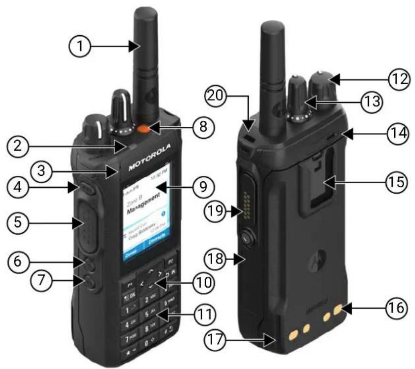
Table 5: Full Keypad Model Overview
| Label Name Description | |
| 1 Antenna To transmit and receive electromagnetic waves. | |
| 2 LED Indicator Provides operating status. | |
| 3 Front Microphone Allows your voice to be sent when PTT or voice operations are activated. | |
| 4 3-Dot Programmable Fea-ture button | Programmable button of an assignable radio function. |
| 5 Push-to-Talk (PTT) but-ton | Allows you to execute voice operations (for example, Group Call and Private Call). |
| 6 1-Dot Programmable Fea-ture button | Programmable button of an assignable radio function. |
| 7 2-Dot Programmable Fea-ture button | Programmable button of an assignable radio function. |
| 8 Emergency button Allows you to turn on and off the Emergency Operations. | |
| 9 Display The radio display screen. | |
Label Name Description
| 10 Keypad Keys that allows you to select and input characters for various text based operations. |
| 11 Speaker Outputs all tones and audio that are generated by the radio (for example, features like keypad tones and voice audio). |
| 12 On/Off/Volume knob Allows you to turn the radio on or off and adjust volume. |
| 13 Channel Selector knob Allows you to select channel. |
| 14 Rear Microphone Noise Cancellation Microphone. |
| 15 Belt Clip Slot Allows you to attach belt clip. |
| 16 Charging Contacts Charging point for the battery. |
| 17 Charging Rail Provides guideline for the placement during charging. |
| 18 Device Labeling Area Area for adhesive label with a recommended size of 34.5 mm(length), 12.8 mm(width), and 1.3 mm at the corner for customization. |
| 19 Accessory Connector Allows you to connect accessories to your radio. |
| 20 Lanyard Hole Allows you to attach lanyard to your radio. |
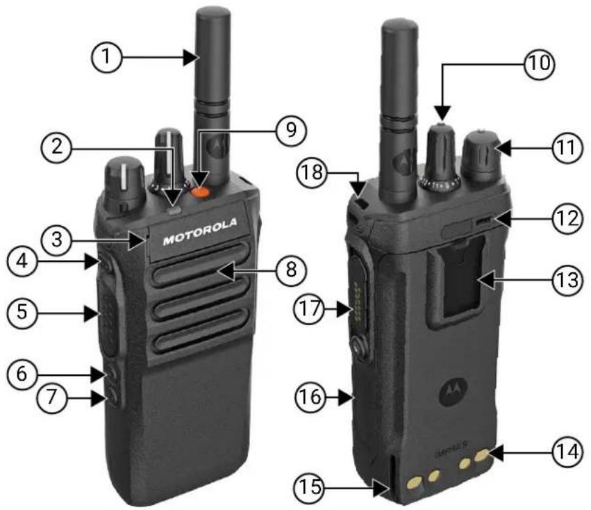
Table 6: Non-Keypad Model Overview
| Label Name Description | ||
| 1 | Antenna | To transmit and receive electromagnetic waves. |
Label Name Description
| 2 LED Indicator Provides operating status. | |
| 3 Front Microphone Allows your voice to be sent when PTT or voice operations are activated. | |
| 4 3-Dot Programmable Feature button | Programmable button of an assignable radio function. |
| 5 Push-to-Talk (PTT) button | Allows you to execute voice operations (for example, Group Call and Private Call). |
| 6 1-Dot Programmable Feature button | Programmable button of an assignable radio function. |
| 7 2-Dot Programmable Feature button | Programmable button of an assignable radio function. |
| 8 Speaker Outputs all tones and audio that are generated by the radio (for example, features like keypad tones and voice audio). | |
| 9 Emergency button To turn on and off the Emergency Operations. | |
| 10 Channel Selector knob Allows you to select channel. | |
| 11 On/Off/Volume knob Allows you to turn the radio on or off and adjust volume. | |
| 12 Rear Microphone ^5 | Noise Cancellation Microphone. |
| 13 Belt Clip Slot Allows you to attach belt clip. | |
| 14 Charging Contacts Charging point for the battery. | |
| 15 Charging Rail Provides guideline for the placement during charging. | |
| 16 Device Labeling Area Area for adhesive label with a recommended size of 34.5 mm (length), 12.8 mm (width), and 1.3 mm at the corner for customization. | |
| 17 Accessory Connector Allows you to connect accessories to your radio. | |
| 18 Lanyard Hole | Allows you to attach lanyard to your radio. |
4.1
Keypad Overview
Figure 3: Keypad Overview
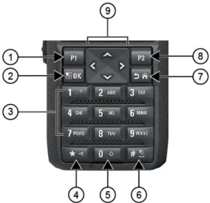
Table 7: Keypad Overview
| Label Button Name Description | |
| 1 Programmable Button 1(P1) | This button is field programmable using the radio programming software. |
| 2 Menu/OK button Press to access Menu feature. | |
| In the menu, use this key to select. | |
| 3 Number keys Press these keys repeatedly until the desired letter, number, punctuation, or symbol appears. | |
| 4 * or delete key During numeric entry, press this key to enter *. | |
| During text entry, press this key to delete a character. | |
| 5 0 key Press to enter 0. | |
| Press and hold to enable or disable Caps Lock. | |
| 6 # or space key During numeric entry, press this key to enter #. | |
| During text entry, press this key to insert a space. | |
| Press and hold this key to change text entry method. | |
| 7 Back/Home button Press to return to previous screen. | |
Label Button Name Description
| Press and hold to return to home screen. | |
| 8 Programmable Button 2 (P2) | This button is field programmable using the radio programming software. |
| 9 4-Way Navigation buttons | Press up, down, left, and right to navigate through your options. |
4.2
Programmable Buttons
You can program the programmable buttons as shortcuts to the following radio functions through programming software.

NOTE: Contact your dealer for more information.
Table 8: Assignable Radio Functions
| Function Description | |
| Acoustic Feedback (AF) Sup-pressor | Allows you to toggle the AF Suppressor feature to on or off. |
| Action List Allows you to launch the action list and start the feature or function from the action list. | |
| All Alert Tones Allows you to toggle all tones and alerts to on or off. | |
| Analog Scrambling Allows you to toggle the Analog Scrambling feature to on or off. | |
| Analog Scrambling Code Allows you to toggle the Analog Scrambling Code feature to on or off. | |
| Audio Profiles Allows you to select the preferred audio profiles. | |
| Audio Record Allows you to record all valid received calls. | |
| Audio Routing Allows you to toggle the audio routing between internal and external speakers. | |
| Audio Toggle Allows you to toggle the audio routing between the internal radio speaker and the wired accessory speaker. | |
| Backlight Allows you to toggle the display backlight to on or off. | |
| Backlight Brightness Allows you to adjust the brightness level. | |
| Battery Indicator | Allows you to check the current status of the battery level. |
| Beacon | Allows you to toggle the Beacon to on or off. |
| Beacon Reset | Allows you to reset the Beacon tone without disabling the beacon. |
| Bluetooth® Audio Switch | Allows you to toggle the audio routing between an internal radio speaker and an external Bluetooth-enabled accessory. |
| Bluetooth Connect | Allows you to initiate a Bluetooth find-and-connect operation. |
| Bluetooth Disconnect | Allows you to terminate all existing Bluetooth connections between your radio and any Bluetooth-enabled devices. |
| Bluetooth Discoverable | Allows you to enable your radio to enter Bluetooth Discoverable Mode. |
| Brightness Allows you to adjust the brightness level. | |
| Busy Queue Cancellation When a non-Emergency call is initiated in a Busy Queue, this allows you to exit the busy mode. When a Emergency call is accepted in a Busy Queue, you cannot cancel it. | |
| Call Alert. Allows you to direct access to the contacts list and select the required contact to send a call alert. | |
| Call Forwarding Allows you to toggle the Call Forwarding to on or off. | |
| Call Log Allows you to select the call log list. | |
| Cancel Allows you to cancel an ongoing call. If the call type is Group Call, then only the call initiator can use this button to cancel an ongoing call. If the call type is Private Call, then both the call initiator and receiver can use this button to cancel an ongoing call (applicable to Display model only). | |
| Channel Announcement Allows you to play zone and channel announcement voice messages in the current channel. | |
| Confirm Allow you to confirm a feature. | |
| Contacts Provides direct access to the contacts list. | |
| Cellular Allows you to toggle cellular to on or off. | |
| Display Mode Allows you to toggle to day or night mode | |
| Emergency Off Allows you to terminate an outgoing emergency call. | |
| Emergency On Allows you to set up an emergency call. | |
| Fall Alert Alarms Allows you to toggle the Fall Alert alarms to on or off. | |
| Fall Alert Alarms Reset | Allows you to cancel the Fall Alert tone and reset the feature timers without disabling the Fall Alert Alarms. |
| Global Navigation Satellite System (GNSS) On or Off | Allows you to toggle the satellite navigation system on or off. |
| Indoor Location | Allows you to toggle the Indoor Location to on or off. |
| Intelligent Audio | Allows you to toggle intelligent audio to on or off. |
| Job Ticket | Allows you to access the Job Tickets folder. |
| Keypad Lock | Allows you to toggle the keypad to lock or unlock. |
| Manual Dial | Allows you to initiate Private Call by entering the subscriber ID. |
| Manual Site Roam | Allows you to start the manual site search. |
| Mic AGC Allows you to toggle the internal microphone automatic gain control (AGC) to on or off. | |
| Monitor | Allows you to monitor a channel. |
| Mute Mode | Allows you to turn Mute Mode on or off. |
| Notifications | Allows you to direct access to the notification list. |
| Nuisance Delete | Allows you to temporarily remove an unwanted channel from the scan list, except the Selected Channel. The nuisance deleted channel will be restored into the scan list, for instance, when radio is powered off and back on again (not applicable in Capacity Plus). |
Function Description
| One Touch Access Allows you to direct access to the predefined call features. | |
| Option Board Feature Allows you to toggle the option board feature(s) to enable or disable the option board-enabled channels. | |
| Permanent Monitor Allows you to monitor a selected channel for all radio traffic until function is disabled (not applicable in Capacity Plus). | |
| Phone Allows you to direct access to the phone contact list. | |
| Phone Exit Allows you to terminate a phone call (applicable to Non-Display or Numeric Display model, Digital mode only). | |
| Play All/Stop Playing Audios Allows you to play all recorded audios or stop playing the recorded audio. | |
| Play Latest/Next Audio Allows you to play the latest or next recorded audio. | |
| Power Level Allows you to toggle the transmit power to high or low. | |
| Privacy Allows you to toggle the privacy to on or off. | |
| Radio Check Allows you to check if the radio is active in the system. | |
| Radio Enable or Disable Allows a target radio to be remotely enabled or disabled. | |
| Radio Name Displays the radio alias on the radio display. | |
| Remote Monitor Allows you to turn on the microphone of a target radio without giving any indications. | |
| Repeater or Talkaround Allows you to toggle between using a repeater and directly communicating with another radio. | |
| Reset Home Channel | Allows you to select a new home channel. |
| Reviving or Enabling radios | Allows you to revive or enable any radio in the system. |
| Ring Alert Type | Allows you to direct access the Ring Alert Type setting. |
| Roam Request | Allows you to request to search for a different site. |
| Scan | Allows you to toggle the scan to on or off. |
| Silence Home Channel Reminder | Allows you to mute the Home Channel Reminder. |
| Site Info | Allows you to view the current Capacity Max or Other Systems site name and ID. |
| Site Lock | Allows you to enable the site lock to search only in current site or disable the site lock to search in other sites as well. |
| Status Allows you to select the status list menu. | |
| Stunning or Disabling radios | Allows you to enable or disable any radio in the system. |
| Telemetry Control | Allows you to control the output pin on a local or remote radio. |
| Text Message | Allows you to select the text message menu. |
| Time and Date Announcement | From the radio programming software, if the Voice Announcement field is set to Text to Speech, the programmable button allows you to hear a voice prompt indicating the current time and date. |
Function Description
| If the Voice Announcement field is set to Voice Announcement Files, the time and date cannot be announced and a negative tone sounds. | |
| NOTE: This feature is only available for the R7 model. | |
| Toggle Call Priority Level Allows you to enable your radio to enter Call Priority Level High or Normal. | |
| Transmit Inhibit Allows you to block all transmission from the radio. | |
| TX Interrupt Remote Dekey Allows you to stop an on-going voice call by dekeying the transmitting radio or terminate the repeater call hang time in order to free up the channel. This button can also be used to end a Remote Monitor session. | |
| Trill Enhancement Allows you to toggle the trill enhancement to on or off. | |
| Unassigned Indicates that the button function has not yet assigned. | |
| Voice Announcement Allows you to toggle the Voice Announcement to on or off. | |
| Voice Operating Transmission (VOX) | Allows you to toggle the VOX to on or off. |
| Wi-Fi Allows you to toggle the Wi-Fi to on or off. | |
| Zone Selection Allows you to select from a list of zones. | |
| Zone Toggle Allows you to switch between 2 zones. | |
Chapter 5
System Overview
System overview explains types of systems and modes available in the radio.
5.1
Capacity Max
Capacity Max is MOTOTRBO control channel based trunked radio system.
MOTOTRBO digital radio products are marketed by Motorola Solutions primarily to business and industrial users. MOTOTRBO uses the European Telecommunications Standards Institute (ETSI) Digital Mobile Radio (DMR) standard, that is, two-slot Time Division Multiple Access (TDMA), to pack simultaneous voice or data in a 12.5 kHz channel (6.25 kHz equivalent).
5.2
Conventional Analog and Digital Modes
Each channel in your radio can be configured as a conventional analog or conventional digital channel.
Certain features are unavailable when switching from digital to analog mode and analog to digital mode, whereas some are available in both.
There are minor differences in how each feature works, but these differences do not affect the performance of your radio.
5.3
IP Site Connect
This feature allows your radio to extend conventional communication beyond the reach of a single site by connecting to different available sites by using an Internet Protocol (IP) network.
When the radio moves out of range from one site and into the range of another, the radio connects to the repeater of the new site to send or receive calls or data transmissions. This is done either automatically or manually depending on your settings.
In an automatic site search, the radio scans through all available sites when the signal from the current site is weak or when the radio is unable to detect any signal from the current site. The radio then locks on to the repeater with the strongest Received Signal Strength Indicator (RSSI) value.
In a manual site search, the radio searches for the next site in the roam list, which may not have the strongest signal, but is in range and locks onto the repeater.

NOTE: Each channel can only have Scan or Roam enabled, not both simultaneously.
Channels with this feature enabled can be added to a particular roam list. The radio searches the channels in the roam list during the automatic roam operation to locate the best site. A roam list supports a maximum of 16 channels, including the selected channel.

NOTE: You cannot manually add or delete an entry in the roam list. Contact your dealer for more information.
5.4
Capacity Plus
Capacity Plus is a cost-effective entry-level digital trunked system. The system is available in single-site and multi-site setups. Capacity Plus expands system capacity compared to non-trunked systems.

NOTE: If you try to access a feature not applicable to Capacity Plus Single-Site or Capacity Plus Multi-Site using a programmable button, you hear a negative indicator tone.
Capacity Plus-Single-Site
Capacity Plus Single-Site is a single-site trunking configuration of the MOTOTRBO radio system, which uses a pool of channels to support hundreds of users and up to 254 groups.
This configuration allows your radio to efficiently use the number of available programmed channels while in Repeater Mode.
Capacity Plus-Multi-Site
Capacity Plus–Multi-Site is a multi-channel trunking configuration of the MOTOTRBO radio system, combining the best of both Capacity Plus and IP Site Connect configurations. It is also known as Linked Capacity Plus.
It allows your radio to extend trunking communication beyond the reach of a single site, by connecting to different available sites which are connected with an IP network. It also provides an increase in capacity by efficiently using the combined number of available programmed channels supported by each of the available sites.
When your radio moves out of range of one site and into the range of another, it connects to the repeater of the new site to send or receive calls or data transmissions. Depending on your settings, this is done automatically or manually.
Automatically
Your radio scans through all available sites when the signal from the current site is weak or unable to detect any signal and locks on to the repeater with the strongest RSSI value.
Manually
Your radio searches for the next site in the roam list that is currently in range which may not have the strongest signal, and locks on to it.
Any channel with Capacity Plus Multi-Site enabled can be added to a roam list. Your radio searches these channels during the automatic roam operation to locate the best site.

NOTE: You cannot manually add or delete an entry in the roam list.
5.5
Direct Mode or Dual Capacity Direct Mode
A direct mode or dual capacity direct mode system is applicable when the transmitter's output power from a user's portable or mobile radio is sufficient for the user to communicate directly with all other users within the required coverage area of the customer.
Direct Mode or Dual Capacity Direct Mode (DCDM) is direct radio-to-radio communication for systems that do not use a repeater. When radios operate in direct mode or dual capacity direct mode, the radios always transmit and receive on the same frequency. Direct mode and dual capacity direct mode provide similar services to the end users, with the exception that dual capacity direct mode is only available in digital mode, and supports two simultaneous voice or data paths on a 12.5 kHz bandwidth channel while direct mode supports only one. There are some minor differences, for example, dual capacity direct mode channels may not be used as GNSS revert channels.
The radios are not limited to one direct mode/dual capacity direct mode frequency. They can be programmed to have different frequencies, which are selectable with the channel selector knob.
Direct mode or dual capacity direct modes do not need over-the-air hang time for voice calls. The radio has an internal call ("talk back") timer. The channel access method used before the call timer expires is impolite, since the radio is still a member of an active call. This is independent of the Channel Access selection for call initiation (polite or impolite).
Chapter 6
WAVE
Wide Area Voice Environment (WAVE ^™ ) provides a method of making calls between two or more radios.
WAVE allows you to communicate across different networks and devices using Wi-Fi. WAVE calls are made when the radio is connected to an IP network through Wi-Fi.
Your radio supports WAVE OnCloud/OnPremise.

NOTE: This feature is not applicable to R7a model.
6.1
WAVE OnCloud/OnPremise
6.1.1
Switching from Radio Mode to WAVE Mode
Procedure:
From the menu, select WAVE Mode.
Result:
The yellow LED double blinks.
The display shows a momentary notice of Switching to WAVE, then shows Preparing WAVE.

NOTE: Your radio automatically enables Wi-Fi after you switch to WAVE mode.
If your radio successfully switches to WAVE mode, your radio shows the following indications:
- The blinking yellow LED turns off.
- The display shows the WAVE connected icon, Talkgroup Alias and
.
If your radio fails to switch to WAVE mode, your radio shows the following indications: - A negative tone sounds.
- The red LED blinks.
- The display shows the WAVE disconnected icon and No Connection or Activation: Fail, depending on the error type.

NOTE: Synchronization occurs when new settings are updated to your radio. When you enter the WAVE mode, your radio displays Syncing.... When the synchronization completes, your radio returns to the home screen.
6.1.2
Switching from WAVE Mode to Radio Mode
Procedure:
From the menu, select Radio Mode.
Result:
The yellow LED double blinks.
The display shows a momentary notice of Switching to Radio and then shows Preparing Radio.
If your radio successfully switches to radio mode, your radio shows the following indications:
- The blinking yellow LED extinguishes.
- The WAVE connected icon disappears on the status bar. The display shows
and .
Chapter 7
Getting Started
This chapter provides instructions on how to prepare your radio for use.
7.1
Charging the Battery
Prerequisites: Turn off your radio when charging.
Procedure:
- To comply with warranty terms and avoid damage, charge the battery using a Motorola Solutions authorized charger as described in the charger user guide.
- Charge a new battery three to four hours before initial use for best performance.
Batteries charge best at room temperature. - If the charger LED blinks in red when charging, you must reinsert the radio. You may need to repeat the step every 15 minutes.
- Charge your IMPRES™ battery with an IMPRES charger for optimized battery life and valuable battery data.

NOTE: MOTOTRBO IMPRES batteries comes with self calibration feature, and do not have to undergo the long hours of calibration or recondition process when charged with the compatible IMPRES Single-Unit Charger and IMPRES 2 Multi-Unit Charger (software version 2.00 and above). You can refer to Authorized Accessories List on page 164.
7.2
Attaching or Detaching the Battery
Attaching the Battery
Procedure:
- Align the battery with the rails on the back of the radio.
- Press the battery firmly, and slide upwards until the latch snaps into place.
- Slide battery latch into lock position.
Postrequisites:

NOTE:
If your radio's Certification Type is set to UL and a wrong battery is attached, your radio shows the following indications:
- A low pitched warning tone sounds.
- The red LED blinks.
- The display shows Wrong Battery.
- The Voice Announcement or Text-to-Speech sounds if loaded using the radio programming software.
For R7a UL capable radio model, to enable UL battery detection, set the radio certification type as UL in MOTOTRBO CPS 2.0 or Radio Management (RM) programming software.
The certification of the radio is voided if you attach a UL battery to an FM approved radio or vice versa. If your radio is attached with a wrong or unsupported/unrecognized battery, immediately swap with the correct battery.
Detaching the Battery
Prerequisites: Ensure that your radio is turned off.
Procedure:
- Move the battery latch into the unlock position.
- Hold and slide the battery down and off the rails.
7.3
Attaching or Detaching the Antenna
Attaching the Antenna
Procedure:
- Set the antenna in the receptacle.
- Turn the antenna clockwise.

NOTE: Fastening the antenna blocks water and dust from entering the radio.

CAUTION: To prevent damages, replace the faulty antenna with only MOTOTRBO antennas.
Detaching the Antenna
Procedure:
- Turn the antenna counterclockwise.
- Remove the antenna from the receptacle.
7.4
Attaching the Universal Connector Cover
Procedure:
- Insert the slanted end of the cover into the slots above the universal connector.
- Press downwards on the cover to seat the cover properly on the universal connector.
- Secure the connector cover to the radio by turning the thumbscrew clockwise.
7.5
Removing the Universal Connector Cover
Procedure:
- Turn the thumbscrew counterclockwise.
- Slide the connector cover up and out of the slanted end of the universal connector.
Postrequisites: Replace the dust cover when the universal connector is not in use.
7.6
Cleaning the Universal Connector Cover
When and where to use: If the radio is exposed to water, dry the universal connector before attaching an accessory or replacing the dust cover. If the radio is exposed to salt water or contaminants, perform the following cleaning procedure.
Procedure:
- Mix one tablespoon of mild dishwashing detergent with one gallon of water to produce a 0.5% solution.
- Clean only the external surfaces of the radio with the solution. Apply the solution sparingly with a stiff, nonmetallic, short-bristled brush.
- Dry the radio thoroughly with a soft and lint-free cloth. Ensure the contact surface of the universal connector is clean and dry.
- Apply Deoxit Gold Cleaner or Lubricant Pen (Manufacturer CAIG Labs, Part number G100P) on the contact surface of the universal connector.
- Attach an accessory to the universal connector to test the connectivity.
Postrequisites:

NOTE: Do not submerge the radio in water. Ensure excess detergent does not get trapped in between the universal connector, controls, or crevices.
Clean the radio once a month for maintenance. For a harsher environment such as in petrochemical plants or in a high salt density marine environment, clean the radio more often.
7.7
Turning the Radio On or Off
Turning the Radio On
Procedure:
Turn the On/Off/Volume knob clockwise until a click sounds.
Result:
If your radio is turned on, your radio shows the following indications:
- A tone sounds.

NOTE: If the Tones/Alerts function is disabled, no tone sounds.
- The green LED illuminates.
- The home screen lights up.
- If voice announcement type is set to Voice Announcement (VA), the Power Up Status Announcement is enabled and Voice Announcement File is attached, the voice announcement sounds the battery level, and other service announcements.
- If voice announcement type is set to Text-to-Speech (TTS), and the Power Up Status Announcement is enabled, the voice announcement sounds the battery level, radio alias, and other service announcements.

NOTE: If your radio fails to turn on although your battery is charged and properly attached, contact your dealer for more information.
Turning the Radio Off
Procedure:
Turn the On/Off/Volume knob counterclockwise until a click sounds.
Result: The display shows Powering Down.
7.8
Holding Your Radio While Transmitting Audio
Procedure:
- When using high audio, hold your radio vertically with the top microphone 5–10 cm away from your mouth.
- Speak into the top microphone.

NOTE: Do not speak facing the bottom or the back of your radio.
- Listen through a speaker.
- Keep the antenna at least 2.5 cm from your head and body.
Result:
The following shows the correct way of holding your radio while transmitting audio.
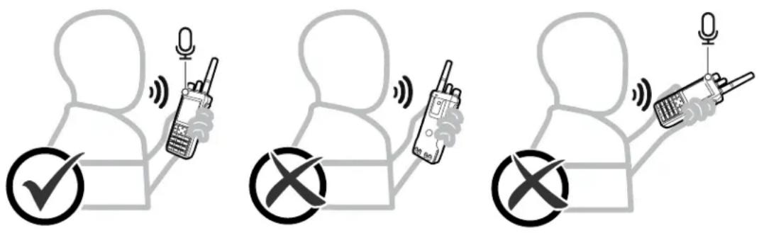
7.9
Adjusting the Volume
Procedure:
Perform one of the following actions:
- To increase the volume, turn the On/Off/Volume knob clockwise.
- To decrease the volume, turn the On/Off/Volume knob counterclockwise.

NOTE:
Your radio can be programmed to have a minimum volume offset where the volume level cannot be lowered past the programmed minimum volume.
A volume bar screen appears when you adjust the volume.
7.10
Inserting the Radio into the Carry Case
Procedure:
- Place your radio in the carry case.
- Button the carry case.
7.11
Removing the Radio from the Carry Case
Procedure:
- Unbutton the carry case.
- Remove the radio from the carry case.
Chapter 8
Home Screen Overview
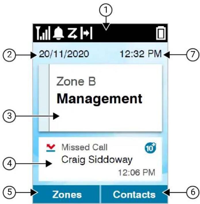
Table 9: Home Screen Overview
| No. Name Description | |
| 1 Status Bar Status icons appear in the status bar to provide device status and feature notifications. | |
| 2 Date The date format available is DD/MM/YYYY (default) and MM/DD/YYYY. | |
| 3 Radio Control Widget Displays channel errors, trunking statuses, call states. | |
| 4 Notification Widget Displays the most recent notification. | |
| 5 Programmable Button 1 (P1) | This button is field programmable using the radio programming soft-wares. |
| 6 Programmable Button 2 (P2) | This button is field programmable using the radio programming soft-wares. |
| 7 Time The time format available is 12 hours (default) and 24 hours. | |
8.1
Status Indicators
Status Indicators explain the Icons and LED indicators used in your radio.
8.1.1
Status Icons
These icons appear at the status bar to provide device-specific information or status.
| Icon Name Description | |
| Auto Roaming Auto Roaming is enabled. | |
 | Battery The number of bars shown indicates the charge remaining in the battery. |
| Bluetooth Connected The Bluetooth feature is enabled. The icon stays lit when a remote Bluetooth device is connected. | |
| [4XAS] | Call Priority High Call Priority Level High is enabled. |
 | Collaboration App Link Your radio is now paired and connected to the IoT devices. |
 | Dynamic Group Number As- signment (DGNA) Your radio is in DGNA Talkgroup. |
 | Download Your radio is currently downloading file or has a downloa- ded file. |
 | Emergency Your radio is in Emergency mode. |
| [XTXS] | Global Navigation Satellite System (GNSS) GNSS feature is enabled. The icon stays lit when a position fix is available. |
 | GNSS error GNSS feature is enabled but is having issue receiving data from the satellite. |
 | GNSS unavailable GNSS feature is enabled but is not receiving data from the satellite. |
| [8CST] | High Volume Data Your radio is receiving high volume data and channel is busy. |
 | Keypad Your radio keypad is in lock or unlock state. |
 | Location Location status is on and available. |
 | Location unavailable Location status is on but unavailable due to Bluetooth disa- bled or Beacons Scan suspended by Bluetooth. |
| [W6WS] | Log available Indicates the log in your radio is ready to be uploaded. |
Icon Name Description

Log uploading Indicates the log in your radio is uploading.

NOTE:
If your radio loses the Wi-Fi connection during the log uploading process, your radio shows the following indications.
- The status bar shows the log available icon instead of the log uploading icon.
- The log uploading process stops.
Once your radio connects to the Wi-Fi connection, your radio shows the following indications.
- The status bar shows the log uploading icon.
- The log uploading process resumes.

Monitor Selected channel is being monitored.

Notification Your radio receives notification of an activity or event.

Option Board The Option Board is enabled.

Option Board unavailable The Option Board is disabled.

Over-the-Air-Programming Indicates time left before automatic restart of radio. (OTAP) Delay Timer

Power Level Your radio is set at low power. Icon disappears when the radio is in high power.

Response Inhibit Prevents your radio from responding to any incoming transmissions.

Received Signal Strength Indicator (RSSI) The number of bars displayed represents the radio signal strength. Four bars indicate the strongest signal. This icon is only displayed while receiving.

Out of Range Your radio unable to detect a signal from the system or current site.

Receiving Your radio is receiving call.

Transmitting Your radio is transmitting call.

Scan Scan feature is enabled.

Scan Priority Your radio detects activity on the channel or group designated as Priority 1 or 2.

Vote Scan Vote scan feature is enabled

Secure The Privacy feature is enabled.

Unsecure The Privacy feature is disabled.

Shared Frequency Indicates that your radio is locking to shared control channel.
| Icon Name Description | |
| Talkaround In the absence of a repeater, radio is currently configured for direct radio to radio communication. | |
| Transmit Inhibit Allows you to block all transmissions from your radio. | |
| Mute Mute is enabled and speaker is muted. | |
| Ring Only Ringing mode is enabled. | |
| Silent Silent mode is enabled. | |
| Tone Disabled Tones are turned off. | |
| Service and Support Indicates that your radio requires service and support. | |
| Wi-Fi Your radio is connected to a Wi-Fi network. The number of bars represents the signal strength of the Wi-Fi network. | |
| Wi-Fi unavailable Wi-Fi network is not available. | |
8.1.2
Bluetooth Device Icons
The following icons appear next to items in the list of Bluetooth-enabled devices available to indicate the device type.
Table 10: Bluetooth Device Icons
| Icon Icon Name | |
| Bluetooth Audio Device | |
| Bluetooth Data Device | |
| Bluetooth PTT Device | |
| Bluetooth PAN Device | |
| Bluetooth Sensor Device | |
8.1.3
Call Icons
The following icons appear on the display during a call. These icons also appear in the Contacts list to indicate alias or ID type.
Table 11: Call Icons
| Icon Icon Name | |
| Bluetooth PC Call | |
| DGNA Call | |
| Dispatch Call | |
| Group Call/All Call | |
| Non-IP Peripheral Individual call | |
| Non-IP Peripheral Group call | |
| Phone Call as Group or All Call | |
| Phone Call as Private Call | |
| Private Call | |
8.1.4
Job Tickets Icons
The following icons appear momentarily on the display in the Job Ticket folder.
Table 12: Job Ticket Icons
| Icon Icon Name | |
| All Jobs | |
| New Jobs | |
| Job In Progress | |
| Job Sent Failed | |
| Job Sent Successfully | |
| 1 | Priority 1 Job |
| 2 | Priority 2 Job |
| 3 | Priority 3 Job |
8.1.5
Mini Notice Icons
The following icons appear momentarily on the display after an action to perform a task is taken.
Table 13: Mini Notice Icons
| Icon Icon Name | |
| ! | Failed Transmission (Negative) |
| √ | Successful Transmission (Positive) |
| ○ | Transmission in Progress (Transitional) |
8.1.6
LED Indications
The LED Indicator shows the operational status of your radio.
A qualified technician can permanently disable the LED indication by preprogramming it.
Table 14: LED Indications
| Indication Status | |
| Blinking Red | The radio is indicating a battery mismatch.The radio has failed the self-test upon powering up.The radio is receiving an emergency transmission.The radio is transmitting in low battery state.The radio has moved out of range if Auto-Range Transponder System is configured.Mute Mode is enabled. |
| Solid Yellow | The radio is in Bluetooth Discoverable Mode.The radio is monitoring a conventional channel. |
| Blinking Yellow | The radio has yet to respond to a Call Alert.The radio is scanning for activity.The radio has Flexible Receive List enabled.All Capacity-Plus-Multi-Site channels are busy. |
| Double Blinking Yellow | The radio has Auto Roaming enabled.The radio is actively searching for a new site.The radio has yet to respond to a Group Call Alert.The radio is locked.The radio is not connected to the repeater while in Capacity Plus.All Capacity-Plus channels are busy. |
| Solid Green | The radio is powering up.The radio is transmitting.The radio is sending a Call Alert or an emergency transmission. |
Indication Status
Blinking Green
- The radio is receiving a call or data.
- The radio is retrieving the Over-the-Air Programming transmissions.
- The radio is detecting activity over the air.
Double Blinking Green The radio is receiving a privacy-enabled call or data.
8.2
Radio Control Widget
The Radio Control Widget displays the current zone and channel, channel errors, trunking statuses, and call states.
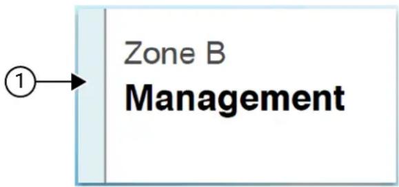
flowchart
graph TD
    A["①"] --> B["Zone B Management"]
No. Name
1 Lightbar
8.2.1
Lightbar Indicators
The Lightbar Indicator indicates the active call state of the radio.
Color Call State
Light Blue Idling

Yellow Receiving Call

Red Transmitting Call
Color Call State

Gray Unprogrammed

8.3
Notification Widget
Notification Widget provides you with important notices. You can take an action directly from the Notification Widget.
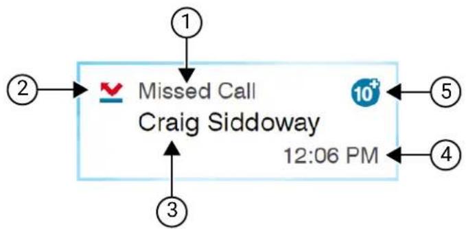
flowchart
graph TD
    A["1"] --> B["Missed Call"]
    C["2"] --> B
    B --> D["Craig Siddoway"]
    E["3"] --> D
    D --> F["12:06 PM"]
    G["5"] --> H["10+"]
    I["4"] --> H
Table 15: Notification Widget Overview
| No. Name Description | |
| 1 Notification Type Displays the most recent notification. | |
| 2 Inline Icon | Displays the icon for the most recent notification. Refer to Notification Widget Icons on page 56 for more information. |
| 3 Caller or Sender ID Status Information | Displays caller or sender ID information based on the recent notification received. |
| 4 Time stamp Information | Displays the time stamp of the received notification. |
| 5 Total Number of Un-read Notification | Displays the total unread notifications. For more that 10 unread notifications, the Notification Widget displays the total number as 10 . |
8.3.1
Notification Widget Icons
These icons appear at the Notification Widget to provide indication for received notification.
| Icon Name | |
| Call Alert | |
| Emergency | |
| Job Ticket | |
| Miss Call | |
| Service and Support | |
| Status Message | |
| Text Message | |
8.4
Screen Saver
The screen saver feature allows your radio to reduce battery consumption and increase battery life.
Under the following conditions, your radio will enter into screen saver mode after the Backlight Timeout Timer expires:
- In the radio programming softwares, the configuration for Backlight → Timeout Timer (sec) is not set to Infinite.
- Your radio remains in home screen.
- Your radio is not in any active voice call or in call hang time state.
- Your radio is not displaying any momentary notice such as home screen reminder or low battery warning.
Your radio will exit the screen saver mode if the following scenarios occur:
- Any user input detected.
- Pressing the PTT button, keypad button, or Programmable button.
○ Launching an Emergency.

NOTE: If your Emergency is configured as Silent or Silent with voice, launching the Emergency will not exit the screen saver mode.
○ Turning the On/Off/Volume knob or Channel Selector knob.
○ Attaching or detaching any accessories.
- Your radio is receiving a voice call.
- Your radio is receiving nonvoice transmission activity such as Call Alert and Job Ticket.
- Your radio is displaying any momentary notice such as home screen reminder or low battery warning.
Chapter 9
Icon-Based Menu Overview
Icon-based menu populates up to nine menu icons per page. Your radio auto-populates Icon-based Menu based on the feature availability.
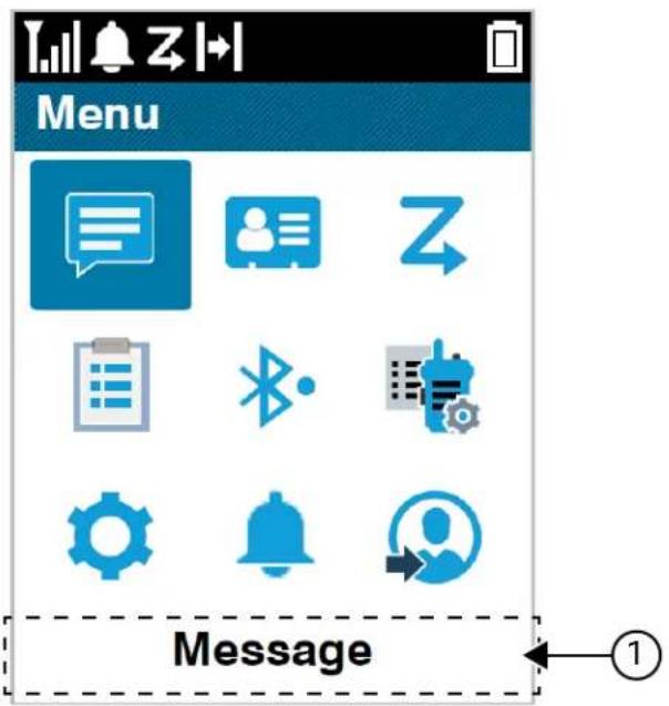
No. Name Description
1 Menu String Displays the name of the corresponding selected menu icon.
9.1
Icon-Based Menu Icons
Icon Name
| Audio Playback | |
| Bluetooth | |
| Call Log | |
| Caller Alias | |
| Contact | |
| Icon Name | |
| Emergency | |
| Job Tickets | |
| Log In | |
| Log Out | |
| Message | |
| Notification | |
| Radio Mode | |
| Scan | |
| Service and Support | |
| Status | |
| Utilities | |
| Wi-Fi | |
| Zone | |
9.2
Accessing Icon-Based Menu
Procedure:
- From the home screen, select the Menu/OK button.
- Navigate the menu by using the 4-Way Navigation button or Number keys.

NOTE: Each number on the Number keys is tied to each icon that appears on the menu.
Chapter 10
Basic Radio Operation
This section explains the basic operations that you can perform on your radio.
10.1
Registration
Your radio may receive registration-related messages from your Capacity Max system.
Registration
Your radio sends registration message to a system when you turn on your radio, change talkgroup, or site roam. If your radio fails to register on site, your radio automatically attempts to roam to another site, and temporarily removes the registration site attempted from the roaming list.
When site searches successfully, your radio shows the following indications:
- A tone sounds.
- The yellow LED double blinks.
- The display shows Registering.
When site registered successfully, your radio shows Site
Out of Range
When your radio unable to detect a signal from the system or from the current site, your radio shows the following indications:
- A repetitive tone sounds.
- The RED blinks.
● The display shows Out of range.
Talkgroup Affiliation Failed
When your radio fails to attempt affiliation to the talkgroup, your radio shows Affiliation Fail.
Registration Denied
When registration with the system is not accepted, your radio shows the following indications:
- The yellow LED double blinks.
- The display shows Registration Denied.
10.2
Site Overview
A site provides coverage for a specific area.
In a multi-site network, the system automatically searches for a new site when the signal level from the current site drops to an unacceptable level.
10.2.1
Site Trunking
Site Trunking is only available with Capacity Max system. A site must be able to communicate with the Trunk Controller to be considered as System Trunking.
If the site cannot communicate with the Trunk Controller in the system, a radio enters Site Trunking mode. While in Site Trunking, the radio provides a periodic audible and visual indication to indicate limited functionality.
When a radio is in Site Trunking, the radio displays Site Trunking and a repetitive tone sounds.
The radios in Site Trunking are still able to make group and individual voice calls as well as send text messages to other radios within the same site. Voice consoles, logging recorders, phone gateways, and data applications cannot communicate to the radios at the site.
Once in Site Trunking, a radio that is involved in calls across multiple sites will only be able to communicate with other radios within the same site. Communication to and from other sites would be lost.

NOTE: If there are multiple sites that cover the current location of the radio and one of the sites enters Site Trunking, the radio roams to another site if within coverage.
10.2.2
Auto Roaming
Depending on your radio system, this feature allows your radio to roam to a required site.
A multi-site channel has auto roaming capability when it is attached with a site search list.
Your radio can roam to different sites through site search.
Table 16: Types of Site Search
| Types Description |
| Passive Site Search (PassiveSS) When Site Lock is turned off, PassiveSS scans available sites and selects the strongest signal as current home. |
| Active Site Search (ActiveSS) ActiveSS sends wakeup requests to the repeater. |
10.2.3
Turning the Site Lock On
Procedure:
Press the programmed Site Lock button.
Result: Your radio shows the following indications:
- A positive tone sounds.
● The display shows Site Locked. - The radio searches in the current site only.
10.2.4
Turning the Site Lock Off
Procedure:
Press the programmed Site Lock button.
Result: Your radio shows the following indications:
- A negative tone sounds.
- The display shows Site Unlocked.
- The radio searches a list of other sites including the current sites.
10.2.5
Enabling the Manual Site Search
Procedure:
- From the menu, select ⚙ Utilities → Radio Settings → Site Roaming.
- Disable the Site Lock.
- Select Active Search.
Result: Your radio shows the following indications:
- A tone sounds.
- The green LED blinks.
If your radio finds a new site, your radio shows the following indications:
- A positive tone sounds.
• The LED extinguishes.
If your radio fails to find a new site, your radio shows the following indications:
- A negative tone sounds.
• The LED extinguishes.
If a new site is within the range, but your radio is unable to connect to it, your radio shows the following indications:
- A negative tone sounds.
• The LED extinguishes.
10.2.6
Accessing Neighbor Sites List
Procedure:
From the menu, select Utilities → Radio Info → Neighbor Sites.
10.3
Zone and Channel Selections
A zone is a group of channels. You can program each channel with different features that support different groups of users.
Table 17: Number of Supported Zones and Channels
| Model Zones Channels Channels per Zone |
| Display 250 1000 160 |
| Non-Display 4 64 16 |
10.3.1
Selecting Zones
Procedure:
From the menu, select

Zone →
Result: The display shows

NOTE: For all Non-Keypad radio, you are recommended to enable the Voice Announcement feature for zone selection. The Voice Announcement feature can only be enabled through the radio programming software.
10.3.2
Selecting Zones Using Alias Search
Procedure:
- From the menu, select

- Enter the required characters for the alias.
Result:
The display shows

NOTE: The alias search is case-insensitive. If there are two or more entries with the same name, the display shows the entry listed first in the list.
10.3.3
Selecting Channels
Procedure:
Turn the Channel Selector knob.

NOTE: If the Virtual Channel Stop is enabled, your radio stops after reaching the first or last channel. You hear a tone.
Result: Your radio switches to your preferred channel.
10.3.4
Selecting Channels Using Direct Channel Dial
Procedure:
At the home screen, enter the
10.4
Responding to Notifications

NOTE: You can customize the notification widget on the home Screen for Private Call and Call Alert features through the Respond Caller setting in the radio programming softwares. When the Respond Caller is enabled, you can directly view a list of notifications for Private Call or Call Alert notification. If the Respond Caller is disabled, the notification is shown in notification widget.
Procedure:
- From the home screen, select the Down button.
- To view the notification detail, select the Menu/OK button.
10.5
Service and Support
You can identify the types of service and support that your radio needs through the service code.
For more information about the Service Code, refer to the MOTOTRBO™ Radios Service Codes
Troubleshooting Guide, MN009539A01 at https://motr.la/docs.
10.5.1
Accessing Service Code for Full Keypad Model
For Full Keypad model, your radio shows the notification alert and service code on the radio display.
Procedure:
Perform one of the following actions:
| Option Actions | |
| Accessing Single Notification Alert | a. From the home screen, select the Down button.b. To view the service code detail and the QR code, select the Menu/OK button.c. To delete the notification, press the Menu/OK button. |
| Accessing Multiple Notification Alert | a. From the home screen, select the Down button.b. To view the notification detail, select the Menu/OK button.c. To view the service code detail and the QR code, select thefrom the notification list.d. To delete the notification, press the Menu/OK button. |
| Accessing The Service Codes From the Service & Support Menu | a. From the menu, select Service & Support.b. Perform one of the following actions:To view the Getting Started page's QR Code, select Get Support.To view the service code detail and the QR code, select thefrom the list. |
Scanning the QR code leads you to the Motorola Solutions Knowledge Portal, where you can find information and recommended actions related to your radio needs. If you are unable to scan the QR code, type the URL below the QR code into a web browser.
10.5.2
Accessing Service Code for Non-Keypad Model
For Non-Keypad model, respective service code messages are only available through Voice Announcement.

NOTE: If the Voice Announcement feature is not enabled in the radio programming software, service mode and service-related announcements are not available for your Non-Keypad model.
Procedure:
- To enter service mode, press and hold the 3-Dot Programmable Feature button for 5 seconds within 10 seconds after your radio is turned on.
-
Perform the following actions:
-
To listen to all service messages, press the 3-Dot Programmable Feature button again.
-
To delete all service messages, press and hold the 1-Dot Programmable Feature button until you hear a valid tone indicating successful deletion of all service messages.
-
To exit service mode, power cycle your radio.

NOTE: When the radio is in service mode, normal radio operations are disabled.
10.5.3
Viewing Service Contact
Viewing Service Contact feature is only available for radio models with display.
Procedure:
From the menu, select Service & Support → Service Contact.
Result: Your radio shows the service contact details.
10.6
Accessing Action List
The Action List contains configurable quick access features. Each feature in the Action List is identified with action list numbers.
Procedure:
From the home screen, select the Up button.
Figure 4: Action List Overview
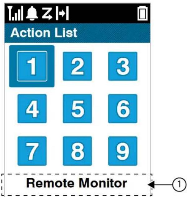
Table 18: Action List Overview
| No. Name Description |
| 1 Feature String Displays the name of the corresponding selected features. |

NOTE: You can configure the Action List and the feature string settings using the radio programming softwares.
10.7
Accessing the Radio Information
Procedure:
- From the menu, select Utilities → Radio Info.
-
To access the radio information, perform one of the following actions:
-
To check on battery information, select Battery Info.
- To check on your radio ID and alias, select My ID.
- To check on the firmware and Codeplug versions, select Versions.
- To check on the GNSS information, select GNSS Info.
- To check on the site information, select Site Info.
- To check on the latest software update information, select SW Update.
10.8
Accessing Text Editor Options
Procedure:
- To enter the Editor Options, press and hold # key.
- From the Editor Options, perform one of the following actions:
| Option Actions | |
| Setting Numeric Input for Number Keys Perform one of the following actions:Select Numbers 123 or Numbers OFF and press Left or Right button.Select Numbers 123 or Numbers OFF and press Menu/OK →. | |
| Adding Required Symbol to Your Text Message | Select Symbols and press Menu/OK →. |
| Setting Predictive or Multi-Tap Options Perform one of the following actions:Select Predictive or Multi-Tap and press Left or Right button.Select Predictive or Multi-Tap and press Menu/OK →NOTE:PredictiveAs you press the required number keys, a list of suggested words appear on the screen.You can choose the correct word from the suggestions for your text message.Multi-TapMulti-Tap requires you to press the required number keys multiple times to select specific letters or symbols. | |
| Selecting The Required Language for Composing Your Text Message | Perform one of the following actions:Selectand press Left or Right button.SelectPress Menu/OK→. |
Chapter 11
General Radio Settings
This section explains the general settings that you can adjust on your radio.
11.1
Talkaround
This feature allows you to continue communicating when your repeater is non-operational, or when your radio is out of range from the repeater but within the talk range of other radios.
The talkaround setting is retained even after powering down.

NOTE: This feature is not applicable in Capacity Plus-Single-Site, Capacity Plus-Multi-Site, and Citizens Band channels that are in the same frequency.
11.1.1
Toggling Between Repeater and Talkaround Mode
Procedure:
- From the menu, select

Utilities → Radio Settings → Talkaround.
- Select the Menu/OK button to toggle between Talkaround or Repeater mode.
Result:
When Talkaround mode is enabled, a √ appears beside Enabled
When Talkaround mode is disabled, the √ disappears beside Enabled
11.2
Setting Date and Time
Procedure:
- From the menu, select

Utilities → Radio Settings → Date & Time.
- Perform one of the following actions:
| Option Actions | |
| Enabling Automatic Synchronization with an Ex-ternal Time Source | a. Enable Set Automatically checkbox with Menu/OK button.b. Proceed to step 7.NOTE:If you enable the Set Automatically, the date and time is synchronized with an external source such as Network Time Protocol (NTP) through Wi-Fi or Global Navigation Satellite System (GNSS). |
| Manually Adjusting the Date and Time | a. Disable Set Automatically checkbox with Menu/OK button.b. Proceed tostep 3. NOTE:If your radio has been off for two weeks, turn your radio on for at least eight hours to recharge the internal battery (coin cell battery) and restore the normal timekeeping function.If the date and time are incorrect, you can manually set the correct date and time in the radio settings. NOTE:If your radio has been off for two weeks, turn your radio on for at least eight hours to recharge the internal battery (coin cell battery) and restore the normal timekeeping function.If the date and time are incorrect, you can manually set the correct date and time in the radio settings. |
- To adjust Time Zone, select the Left, Right, or Menu/OK button.
- To enable Daylight Savings, select Enabled.
- To adjust Set Date, select the Menu/OK →
→ Menu/OK. - To adjust Set Time, select the Menu/OK →
→ Menu/OK. - To adjust Date Format, select the Left, Right, or Menu/OK button.

NOTE: The date format available is DD/MM/YYYY (default) and MM/DD/YYYY.
- To enable 24 hours Time Format, select 24-Hours Time.
11.3
Setting Radio Tones and Alerts
Procedure:
- From the menu, select Utilities → Radio Settings → Tones/Alerts.
-
Select one of the following options:
-
All Tones
- Talk Permit
- Keypad Tone
- Power Up Tone
- Vol.Offset →
.
Result: A √ appears beside the setting.
11.4
Setting Power Levels
Procedure:
- From the menu, select ⚙ Utilities → Radio Settings → Power.
-
Perform one of the following actions:
-
To enable communication with radios located at a considerable distance from you, select High.
● To enable communication with radios in closer proximity, select Low.
11.5
Adjusting Display Settings
Procedure:
- From the menu, select Utilities → Radio Settings → Display.
-
Select one of the following options:
-
Day Mode/Night Mode
- Brightness
- Menu Timer
- Intro Screen
11.6
Setting Squelch Levels
You can adjust the squelch level to filter out unwanted calls with low signal strength or channels with noise higher than normal background.
Procedure:
- From the menu, select Utilities → Radio Settings → Squelch.
-
Perform one of the following actions:
-
For a normal squelch level, select Normal Squelch.
- To filter out unwanted calls or background noise, select Tight Squelch.
11.7
Keypad Lock Options
With this feature, you can avoid accidentally pressing buttons or changing channels when your radio is not in use. Depending on your requirements, you can lock your keypad, channel selector knob, or both.
Your dealer can configure one of the following options with the radio programming software:
- Lock Keypad
- Lock Channel Selector Knob
- Lock Keypad and Channel Selector Knob
Contact your dealer to determine how your radio has been programmed.
11.7.1
Locking or Unlocking the Keypad
Procedure:
Perform one of the following actions:
- To lock the keypad, from the menu, select ⚙ Utilities → Radio Settings → Keypad Lock.
- To unlock the keypad, press Menu/OK → * or delete key.
Result:
If the keypad is locked, the display shows a √beside Enabled If the keypad is unlocked, the √disappears beside Enabled
11.8
Setting Languages
Procedure:
From the menu, select ⚙ Utilities → Radio Settings → Languages →
11.9
Setting the Global Navigation Satellite System
Procedure:
- From the menu, select Utilities → Radio Settings → GNSS.
- Perform one of the following actions:
- To enable GNSS, select the Menu/OK button.
- To disable GNSS, select the Menu/OK button.
Result:
When GNSS is enabled, a √ appears beside Enabled.
When GNSS is disabled, a √ disappears beside Enabled.

NOTE: When GNSS is enabled, the radio location data is transmitted to dispatcher services. Dispatcher Services settings determine the usage of the radio location data.
11.10
Setting LED Indicators
Procedure:
- From the menu, select ⚙ Utilities → Radio Settings → LED Indicator.
-
Perform one of the following actions:
-
To enable LED Indicator, select Menu/OK button.
- To disable LED Indicator, select Menu/OK button.
Result:
If the LED Indicator is enabled, a √ appears beside Enabled
If the LED Indicator is disabled, your radio shows the following indications:
- The √ disappears beside Enabled
- The display backlight and keypad backlight are automatically turned off.
11.11
Password Lock
You can set a password to restrict access to your radio. Each time you turn on your radio, you must enter the password.
Your radio supports a four-digit password input.
Your radio is unable to receive calls in locked state.
11.11.1
Accessing Radios with Password
Prerequisites: Turn on your radio.
Procedure:
Enter your four-digit password.
Result:
If you enter the password correctly, your radio turns on.
If you enter the password incorrectly, a tone sounds, the yellow LED illuminates, and the display shows Wrong Password

NOTE:
You can repeat the steps to enter the password. You are given three attempts before your radio enters into a locked state for 15 minutes. The display shows Radio Locked.
During locked state, your radio responds to inputs from the On/Off/Volume knob and the programmed Backlight button only.
If you restart your radio during the locked state, the timer restarts.
11.11.2
Unlocking Radios in Locked State
Procedure:
To unlock your radio in locked state, perform one of the following actions:
| Option Actions | |
| Unlocking Radios in Locked State if your radio is turned on | a. Wait for 15 minutes.b. Access the radio by following the steps in Accessing Radios with Password. |
| Unlocking Radios in Locked State if your radio is turned off | a. Turn on your radio.NOTE: Your radio restarts the 15 minutes timer for locked state.b. Wait for 15 minutes.c. Access the radio by following the steps in Accessing Radios with Password. |
11.11.3
Setting the Password Lock
Procedure:
- From the menu, select ⚙ Utilities → Radio Settings → Passwd Lock →
.

NOTE: When using this feature for the first time, the display shows New Password Setup to set a new password. You must set a new password before setting the Password Lock feature.
-
Perform one of the following actions:
-
To enable Password Lock, select Turn On.
- To disable Password Lock, select Turn Off.

WARNING: When the Password and Lock feature is disabled, security and privacy protections are removed. Disabling this feature increases the risk of:
- Unauthorized access, deletion, or modification of your data. Your personal data can become more accessible to unauthorized parties.
- Increased vulnerability to data exposure and cyberattacks.
11.11.4
Changing Passwords
Procedure:
- From the menu, select PWD.
Utilities → Radio Settings → Passwd Lock →
→ Change - Enter a new four-digit password.
- To confirm the new password, re-enter the same four-digit password.
Result:
If the password is successfully changed, the display shows Password Changed
If the password change is unsuccessful, the display shows Password Do Not Match and returns to the previous menu.
11.12
Setting the Voice Announcement
Procedure:
- From the menu, select Utilities → Radio Settings → Voice Announcement.
- Perform one of the following actions:
- To enable Voice Announcement, select the Menu/OK button.
- To disable Voice Announcement, select the Menu/OK button.
Result:
If the Voice Announcement is enabled, a √ appears beside Enabled
If the Voice Announcement is disabled, the √ disappears beside Enabled
11.13
Text-to-Speech
This feature enables the radio to audibly indicate the following features:
- Current Channel
- Current Zone
- Programmed button feature on or off
- Content of received text messages
- Content of received Job Tickets

NOTE: If Text-to-Speech is enabled, the Voice Announcement feature is automatically disabled. If Voice Announcement is enabled, then the Text-to-Speech feature is automatically disabled.
11.13.1
Setting the Text-to-Speech
Procedure:
- From the menu, select Utilities → Radio Settings → Text-to-Speech.
- Select one of the following options:
• All
- Messages
- Job Tickets
- Channel
- Zone
- Program Button
Result: A √ appears beside the selected setting.
11.14
Setting the Microphone Automatic Gain Control
Procedure:
- From the menu, select Utilities → Radio Settings → Mic AGC.
-
Perform one of the following actions:
-
For Analog Microphone Automatic Gain Control, select Mic AGC-A.
-
For Digital Microphone Automatic Gain Control, select Mic AGC-D.
-
Perform one of the following actions:
-
To enable Mic AGC, select the Menu/OK button.
- To disable Mic AGC, select the Menu/OK button.
Result:
If the Mic AGC is enabled, a √ appears beside Enabled
If the Mic AGC is disabled, the √ disappears beside Enabled
11.15
Setting the Microphone Distortion
Procedure:
- From the menu, select Utilities → Radio Settings → Mic Distortion.
- Perform one of the following actions:
- To enable Mic Distortion, select the Menu/OK button.
- To disable Mic Distortion, select the Menu/OK button.
Result:
If the Mic Distortion is enabled, a √ appears beside Enabled.
If the Mic Distortion is disabled, the √ disappears beside Enabled.
11.16
Setting the Noise Suppress
Procedure:
- From the menu, select Utilities → Radio Settings → Noise Suppress.
-
Perform one of the following actions:
-
To enable Noise Suppress in a normal background, select Basic.
- To enable Noise Suppress for both quiet and noisy backgrounds, select Enhanced Auto. Effective noise suppression is dynamically applied based on the backgrounds. For quiet backgrounds, relaxed noise suppress is applied. For noisy backgrounds, maximum noise suppress is applied.
- To disable Noise Suppress, select Disabled.
- To enable AI-trained level 1 noise suppression, which removes some of the background noise while still retaining contextual awareness, select AI-trained 1.
- To enable AI-trained level 2 noise suppression for minimal background noise, select AI-trained 2.

NOTE:
- AI-trained 1 is an Artificial Intelligence trained noise reduction technology for advanced noise suppression of background noise. Level 1 refers to a noise suppression level that allows some background noise to be heard for contextual awareness.
- AI-trained 2 is an Artificial Intelligence trained noise reduction technology for advanced noise suppression of background noise. Level 2 refers to a noise suppression level that minimizes background noise for clearer speech.
11.17
Setting the Audio Ambience
Procedure:
- From the menu, select Utilities → Radio Settings → Audio Ambience.
- Perform one of the following actions:
- For default factory settings, select Default.
- To increase the volume of the speaker in noisy surroundings, select Loud.
- To reduce the acoustic feedback when communicating with a group of radios that are near each other, select Work Group.
Result:
The display shows a √ beside the selected setting.
11.18
Setting Audio Profiles
Procedure:
- From the menu, select Utilities → Radio Settings → Audio Preference.
-
Perform one of the following actions:
-
To disable the previous selected audio profile and return to the default factory settings, select Default.
- For audio profiles that compensate noise-induced hearing loss in adults above 40 years old, select Level 1, Level 2, or Level 3.
Result:
The display shows a √ beside the selected setting.
11.19
Setting the Text Entry
You can configure different text entries on your radio.
Procedure:
- From the menu, select Utilities → Radio Settings → Text Entry.
- Perform one of the following actions:
| Option Actions | |
| Setting your radio to learn common word sequences that you often enter | Select Word Predict. |
| Setting your radio to perform word correction Select Word Correct. | |
| Setting your radio to capitalize the first letter in the first word for every new sentence | Select Sentence Cap. |
| Setting custom words | To view custom words, select My Words → List of Words.To edit a custom word, select My Words → Edit.To add a custom word, select My Words → Add New Word.To delete a custom word, select My Words → → Delete.To delete all custom words, select My Words → Delete All. |
Result:
- If you select Word Predict, Word Correct, or Sentence Cap, a √ appears beside Enabled.
- If you select My Words, the display shows a transitional mini notice.
11.20
Voice Operating Transmission
Voice Operating Transmission (VOX) allows you to initiate hands-free voice-activated calls on a programmed channel. When your VOX-capable accessory detects voice, your radio automatically transmits for a programmed period.

NOTE:
This feature is not applicable in Citizen Band channels that are in the same frequency.
Contact your dealer or administrator for more information.
11.20.1
Setting the Voice Operating Transmission
Procedure:
- From the menu, select Utilities → Radio Settings → VOX
-
Perform one of the following actions:
-
To enable VOX, select On.
- To disable VOX, select Off.
Result: If VOX is turned on, the display shows a √ beside On
11.21
Selecting Cable Type
Procedure:
- From the menu, select Utilities → Radio Settings → Cable Type.
- Select one of the following options:
- Motorola
- Data
- Telemetry
- MB PTT
- Data/Audio
Result:
The display shows a beside the selected setting.
Chapter 12
Types of Radio Calls
There are several ways that you can make a call with your radio depending on the types of calls and system available on your radio.
Table 19: Types of Radio Calls
| Call Type Capacity | Max | Conventional Modes | IP Site Connect | Capacity Plus | WAVE |
| Group CallA Group Call is a point-to-multipoint call operation. Your radio must be configured as a member of the group for you to communicate with each other. | √ | √ | √ | √ | √ |
| Broadcast CallA Broadcast Call is a one-way voice call from any user to an entire talk-group.The Broadcast Call feature allows only the call initiating user to transmit to the talkgroup, while the recipients of the call cannot respond. | √ | √ | √ | √ | ✕ |
| Private CallA Private Call is a call from an individual radio to another individual radio.There are two types of Private call which are:Off Air Call Set-Up (OACSU)6Full Off Air Call Set-Up (FOAC-SU)7 | √ | √8 | √ | √ | √9 |
| All CallAn All Call is a call from an individual radio to every radio on the site or every radio at a group of sites. It is used to make important announcement. | √ | √ | √ | √ | ✕ |
| Selective CallA Selective Call is a call from an individual radio to another individual radio. It is a Private Call on an analog system. | ✕ | √ 10 | ✕ | ✕ | ✕ |
| Unaddressed CallAn Unaddressed Call is a group call to one of the 16 predefined group IDs. | ✕ | √ 8 | √ | ✕ | ✕ |
| Open Voice Chanel Mode (OVCM)An OVCM is a call from a radio that is not preconfigured to work in a particular system during a group or individual call. The OVCM group call supports broadcast calls. | ✕ | √ 8 | √ | ✕ | ✕ |
When a call is interrupted, you hear a continuous Talk Prohibit Tone. Releasing the PTT button allows you to receive the call.
Channel Free Indication feature can be programmed on your radio by your dealer. If the Channel Free Indication feature is enabled, you hear a short alert tone when the recipient releases the PTT button, indicating the channel is free for you to respond.

NOTE: If you would like to make a 5-Tone Call, you are required to purchase for a Software License Key separately.
12.1
Making Calls on the Radio
Procedure:
Perform one of the following actions based on the type of calls:
| Option Actions | |
| Making group calls, private calls, unaddressed calls, selective calls or OVCM calls | a. Select a channel with an active ID or alias.b. To call, press and hold the PTT button.c. Wait for the Talk Permit Tone to end, and speak into the microphone.d. To listen, release the PTT button. |
| Making broadcast calls or all calls | a. Select a channel with an active group ID or alias.b. To call, press and hold the PTT button. |
If your radio does not detect voice activity for a predetermined period, the call ends.
12.2
Making Calls with Contact List
Procedure:
Perform one of the following actions based on the type of calls:
| Option Actions | |
| Making group calls or private calls with Contact List | a. From the menu, select Contacts.b. Perform one of the following actions:To do alias search, enter the required characters for the alias.To search for the alias manually, scroll down the contact list with the 4-Way Navigation button.c. To call, press and hold the PTT button.d. Wait for the Talk Permit Tone to end, and speak into the microphone.e. To listen, release the PTT button. |
| Making broadcast calls or all calls with Contact List | a. From the menu, select Contacts.b. Perform one of the following actions:To do alias search, enter the required characters for the alias.To search for the alias manually, scroll down the contact list with the 4-Way Navigation button.c. To call, press and hold the PTT button.d. Wait for the Talk Permit Tone to end, and speak into the microphone. |
| Making selective calls with Contact List | a. From the menu, select Contacts → MDC.b. Navigate to thewith the 4-Way Navigation button.c. To call, press and hold the PTT button.d. Wait for the Talk Permit Tone to end, and speak into the microphone. |
12.3
Making Calls with Manual Dial
Making calls with manual dial is applicable to Private Call only.
Procedure:
- From the menu, select Contacts → Manual Dial → Radio Number.
- To enter or edit the ID, enter the required numbers.
- To call, press and hold the PTT button.
- Wait for the Talk Permit Tone to end, and speak into the microphone.
- To listen, release the PTT button.
12.4
Making Calls with Programmable Number Keys
Procedure:
Perform one of the following actions based on the type of calls:
| Option Actions | |
| Making group calls or private calls with Programmable Number Keys | a. From the home screen, to make a call to the predefined alias, press and hold the programmed number key.b. To call, press and hold the PTT button.c. Wait for the Talk Permit Tone to end, and speak into the microphone.d. To listen, release the PTT button. |
| Making broadcast calls or all calls with Programmable Number Keys | a. From the home screen, to make a call to the predefined alias, press and hold the programmed number key.b. To call, press and hold the PTT button.c. Wait for the Talk Permit Tone to end, and speak into the microphone. |
12.5
Receiving and Responding to Calls on the Radio
When you receive calls, your radio shows the following indications:
- The green LED blinks.
- Your radio unmutes and the incoming call sounds through the speaker.
- The display shows the ID and alias and call status.

NOTE: You cannot respond to a Broadcast Call or All Call. For Broadcast Call, the display shows Talkback Prohibit and the Talkback Prohibit tone sounds when the PTT button is pressed.
Procedure:
- To respond, press and hold the PTT button.
- Wait for the Talk Permit Tone to end, and speak into the microphone.
- To listen, release the PTT button.
12.6
Accepting or Declining Private Calls
When you receive Private Calls configured as Full Off Air Call Set-Up (FOACSU), your radio shows the following indications:
- The green LED blinks.
- The display shows the alias and the Private Call icon.
Accepting Private Calls
Procedure:
-
To accept Private Calls, perform one of the following actions:
-
Select Accept.
-
Press and hold the PTT button.
-
Wait for the Talk Permit Tone to end, and speak into the microphone.
-
To listen, release the PTT button.
Declining Private Calls
Procedure:
To decline Private Calls, perform one of the following actions:
- Select Reject.
- Select the Back/Home button.
- For Non-Keypad radio, press the programmed Cancel button.
Chapter 13
Phone Calls
A Phone Call is a call between individual radios or a group of radios and a telephone.
Depending on the configuration of your radio, the following features are either available or unavailable:
- Access code.
- Dual Tone Multi Frequency (DTMF) tone.
- De-access code.
- Displaying of caller alias or ID on receiving a phone call.
- Ability to reject or accept a phone call.
The Phone Call capability can be enabled by assigning and setting up phone numbers on the system. Contact your dealer to determine how your radio has been programmed.
13.1
Making Phone Calls
Procedure:
- From the menu, select Phone →
→ . - To call, press and hold the PTT button.
- To listen, release the PTT button.
- While you are in the Phone call, you can perform any of the following actions if required:
- Enter extra digits by using the Keypad.
- To end the call, select the Back/Home button.
- To deaccess a code, enter the deaccess code by using the Keypad when the display shows De-Access Code:
Result: If the call ends successfully, your radio shows the following indications:
- A tone sounds.
● The display shows Call Ended.
13.2
Making Phone Calls with Contact List
Procedure:
- From the menu, select Contact.
- Perform one of the following actions:
- To do alias search, enter the required characters for the alias.
- To search for the alias manually, scroll down the contact list with the 4-Way Navigation button.
-
Select Call Phone →
. -
To call, press and hold the PTT button.
-
Select Call Phone →
. -
To call, press and hold the PTT button.
-
To listen, release the PTT button.
-
While you are in the Phone call, perform one of the following actions:
-
Enter extra digits by using the Keypad.
- To end the call, select the Back/Home button.
- To deaccess a code, enter the deaccess code when the display shows De-Access Code:
Result: If the call ends successfully, your radio shows the following indications:
- A tone sounds.
- The display shows Call Ended.
13.3
Making Phone Calls with Manual Dial
Procedure:
- From the menu, select 📁 Contact → Manual Dial → Phone Number.
- Enter the phone number and
. - To call, press and hold the PTT button.
- To listen, release the PTT button.
-
While you are in the Phone call, perform one of the following actions:
-
Enter extra digits by using the Keypad.
- To end the call, select the Back/Home button.
- To deaccess a code, enter the deaccess code when the display shows De-Access Code:.
Result: If the call ends successfully, your radio shows the following indications:
- The display shows Call Ended.
13.4
Dual Tone Multi Frequency
The Dual Tone Multi Frequency (DTMF) feature allows your radio to operate in a radio system with an interface to the telephone systems.
13.4.1
Initiating the DTMF Tone
Procedure:
- Press and hold the PTT button.
-
To initiate a DTMF tone, perform one of the following actions:
-
Enter the
. - Press the * or # button.

NOTE: Disabling all radio tones and alert will automatically turn off the DTMF tone.
13.5
Receiving and Responding to Phone Calls
When you receive a phone call, your radio shows the following indications:
- The green LED blinks.
- Your radio unmutes and the incoming call sounds through the speaker.
- The display shows the Phone Call icon and the call status.
Procedure:
- To respond to the phone call, press and hold the PTT button.
- Wait for the Talk Permit Tone to end, and speak into the microphone.
- To listen, release the PTT button.
- To end the call, select the Back/Home button.

NOTE: Your radio is not able to terminate a phone call as a group call. The telephone user must end the call. The recipient user is only allowed to talk back during the call.
Result: If the call ends successfully, your radio shows the following indications:
- A tone sounds.
● The display shows Call Ended.
Chapter 14
Audio Recording
This feature enables your radio to record valid received voice calls.
Your radio records every received talkback transmission into separate audio files.
The maximum duration for each recording is 2 minutes. For received call longer than 2 minutes, the radio stops the recording even when the call is still ongoing.
Your radio is able to record and store up to five latest valid received calls. The oldest recordings are deleted when it reaches the maximum number.

NOTE: You cannot manually delete any audio files. The audio files can only be deleted through the radio programming software. Contact your dealer or administrator for more information.
14.1
Accessing Audio Playback
Prerequisites: Ensure to enable Audio Recording in the radio programming software.
Procedure:
Perform one of the following actions:
| Option Actions | |
| Accessing audio play back using the Menu/OK button | a. To play the audio, select Playback →Menu/OK →.b. To stop the audio, select the Menu/OK button. |
| Accessing audio play back using the program-mable button | To play or stop the audio, press the program-med Play All/Stop Playing Audios or Play Lat-est/Next Audio. NOTE:If you press the programmed Play All/Stop Playing Audios while the audio is playing, the radio stops the on-going playback.If you press the programmed Play All/Stop Playing Audios when there is no playback is in progress, the radio plays all the audio in the list.If you press the programmed Play Latest/Next Audio while playing a list of audio, the radio skips to the next audio.If you press the programmed Play Latest/Next Audio when there is no playback is in progress, the radio plays the latest audio in the list. |
Chapter 15
Switching Audio Route between Internal Radio Speaker and Wired Accessory
Prerequisites:
Attach a wired accessory with speaker to your radio.
Ensure that the audio is not routed to an external Bluetooth accessory.
Procedure:
Switch the audio route between the internal speaker of your radio and the speaker of the wired accessory by pressing the programmed Audio Toggle button.

NOTE: Turning off your radio or detaching the accessory resets the audio routing to the internal speaker of your radio.
Result:
If the audio route is switched, a tone sounds.
Chapter 16
Connectivity
You can connect your device to other devices, accessories, or network through different types of connectivity.
16.1
Wi-Fi Operation
Wi-Fi® is a registered trademark of Wi-Fi Alliance®. You can set up and connect Wi-Fi network to update your radio firmware, codeplug, language pack, and Voice Announcement.

NOTE: The Wi-Fi feature is not applicable for the R7a model.
Your radio supports the following Wi-Fi networks.
Wi-Fi Enhanced Open
A new WFA security standard for public networks which provides encryption and privacy on open, non-password-protected networks in areas such as cafes, hotels and airports.
WPA/WPA2/WPA3-Enterprise Wi-Fi network
Designed for enterprise networks and requires a RADIUS authentication server. Your radio must be pre-configured with a certificate if certificate-based authentication is deployed and client certificate verification is required.

NOTE: Configure your Wi-Fi system according to the latest industry security recommendations or use Enterprise Wi-Fi.
16.1.1
Turning the Wi-Fi On or Off
Procedure:
- From the menu, select WiFi → WiFi Status.
- To turn on or off the Wi-Fi, select the Menu/OK button.
Result:
If the Wi-Fi is turned on, the display shows a √appears beside Enabled.
If the Wi-Fi is turned off, the √disappears beside Enabled.
16.1.2
Turning Wi-Fi On Remotely Using a Designated Radio
Procedure:
- Perform one of the following actions:
| Option Actions | |
| Selecting the required ID or alias with Contact List | From the menu, select Contact →. |
| Selecting the required ID or alias with Manual Dial | a. From the menu, select Contact → Manual Dial → Radio Number.b. Enter the ID.c. Select the Menu/OK button. |
| Selecting the required group ID or alias with Contact List | From the menu, select Contact → Wi-Fi Control. |
- Select Wi-Fi Control.
- To turn on Wi-Fi, select On.
Result:
If Wi-Fi is turned on, the display shows √
If Wi-Fi fails to turn on, the display shows .
16.1.3
Turning Wi-Fi Off Remotely Using a Designated Radio
Procedure:
- Perform one of the following actions:
| Option Actions | |
| Selecting the required ID or alias with Contact List | From the menu, select Contact →. |
| Selecting the required ID or alias with Manual Dial | a. From the menu, select Contact → Manual Dial → Radio Number.b. Enter the ID.c. Select the Menu/OK button. |
| Selecting the required group ID or alias with Contact List | From the menu, select Contact → → Wi-Fi Control. |
- Select Wi-Fi Control.
- To turn off Wi-Fi, select Off.
16.1.4
Network Access
16.1.4.1
Connecting to a Network Access Point
When you turn on Wi-Fi, your radio scans and connects to a network access point.
Procedure:
- From the menu, select Wi-Fi → Networks →
→ Connect.

NOTE: For WPA-Enterprise Wi-Fi, if a network access point is not preconfigured, the Connect option is not available.
-
Perform one of the following actions:
-
For WPA-Personal Wi-Fi, enter the password.
- For WPA-Enterprise Wi-Fi, the WPA is configured using the radio programming softwares.
If the password is correct, your radio automatically connects to the selected network access point. If the password is incorrect, the display shows Authentication Failure, and automatically returns to the previous menu.
Result:
If the connection is successful, your radio displays a positive notice and the network access point is automatically saved into your profile list.
If the connection is unsuccessful, your radio displays a negative notice screen and returns to the previous menu.
16.1.4.2
Checking Wi-Fi Connection Status
Procedure:
Press the programmed Wi-Fi Status Announcement button.
Result:
If Wi-Fi connection is turned on and connected to a network, your radio shows the following indications:
- A voice prompt indicates that Wi-Fi is turned on.
● The display shows Wi-Fi On, Connected
If Wi-Fi connection is turned on but not connected to any network, your radio shows the following indications:
● A voice prompt indicating that Wi-Fi is turned on.
● The display shows Wi-Fi On, Disconnected
If Wi-Fi connection is turned off, your radio shows the following indications: - A voice prompt indicating that Wi-Fi is turned off.
• The display shows Wi-Fi Off
16.1.4.3
Refreshing Network Lists
Procedure:
From the menu, select Wi-Fi → Networks → Refresh.
Result: Your radio displays the latest network list.
16.1.4.4
Adding a Network

NOTE: This task is not applicable to WPA-Enterprise Wi-Fi networks.
Procedure:
- From the menu, select Wi-Fi → Networks → Add Network.
- Enter the Service Set Identifier (SSID).
- Select WPA/WPA2.
- Enter the password.
- Select the Menu/OK button.
Result: The display shows a mini positive notice.
16.1.4.5
Viewing Details of Network Access Points
Procedure:
From the menu, select Wi-Fi → Networks →
Result:
For WPA-Personal Wi-Fi networks, your radio shows the following details:
- For a connected network access point, your radio displays information on:
○ Service Set Identifier (SSID)
- Security Mode
- Media Access Control (MAC) address
- Internet Protocol (IP) address
- For a non-connected network access point, your radio displays information on:
○ SSID
- Security Mode
For WPA-Enterprise Wi-Fi networks, your radio shows the following details:
- For a connected network access point, your radio displays information on:
○ SSID
- Security Mode
○ Identity
○ Extended Authentication Protocol (EAP) Method
- Phase 2 Authentication
○ Cert Name
○ MAC address
- IP address
- Gateway
○ DNS1
○ DNS2
- For a non-connected network access point, your radio displays information on:
○ SSID
- Security Mode
○ Identity
- EAP Method
- Phase 2 Authentication
○ Certificate Name
16.1.4.6
Removing Network Access Points

NOTE: This task is not applicable to WPA-Enterprise Wi-Fi networks.
Procedure:
From the menu, select Wi-Fi → Networks →
Result: The display shows a positive mini notice.
16.1.5
Accessing Enterprise Wi-Fi Network
Procedure:
-
From the menu, select Utilities → Certificate Menu → Cert. 3.
-
Perform one of the following actions:
• To enroll the certificate, select Enroll.
- To update the password, select Password →
- To view the certificate details, select View Details.
Result:
If the certificate enrollment is completed successfully, a √ appears beside Cert. 3.
If the certificate fails to enroll, an error message appears and returns to the previous menu.
If updating the password successfully, the display shows a mini positive notice.
If the certificate is ready, you are able to view a list of details.
If the certificate is not ready, you are able to view the status only.
16.2
Bluetooth®
This feature allows your radio to connect to any Bluetooth enabled device through Bluetooth connection.

NOTE: The Bluetooth feature is not applicable for the R7a model.
Ensure a clear path between your radio and your Bluetooth-enabled device. For optimal reliability, Motorola Solutions recommends to not separate the radio and the Bluetooth enabled device.
If the voice and tone quality is distorted or unclear, place your radio and the Bluetooth enabled device closer together to improve audio reception.
Your radio can support up to three simultaneous Bluetooth connections with Bluetooth-enabled devices of unique types. Your radio connects to the Bluetooth-enabled device within range with either the strongest signal strength or last connected device.
For more details on the full capabilities, refer to the user manual of your respective Bluetooth-enabled device.

NOTE:
- Do not turn off your Bluetooth-enabled device or select the Back/Home button during the finding operation as this cancels the operation.
- Use the latest Bluetooth accessories (v5.0 and above) for enhanced connection security.
● Always adopt Bluetooth security best practices when using Bluetooth devices.
16.2.1
Turning the Bluetooth On or Off
Turning Bluetooth On
Procedure:
From the menu, select Bluetooth → My Status → On.
Result: If Bluetooth is turned on, the display shows a √ beside Bluetooth On.
Turning Bluetooth Off
Procedure:
From the menu, select Bluetooth → My Status → Off.
Result: If Bluetooth is turned off, the display shows a √ beside Bluetooth Off.
16.2.2
Connecting to Bluetooth Devices
Procedure:
- For Full Keypad radios, from the menu, select Bluetooth.
2. Perform one of the following actions:
| Options Actions | |
| Connecting through Full Keypad radios Perform one of the following actions:a. To connect to a previously connected device, select Devices →Connect.b. To connect to a new device, select Devices → Find Devices → Connect.c. To connect to a device in discoverable mode, select Find Me. | |
| Connecting through Non-Keypad radios Perform one of the following actions:a. To connect to a previously connected device, press the Bluetooth Connect button.b. To connect to a new device, perform the following actions:i. Configure the Bluetooth Accessory MAC address in the radio programming software.ii. Press the programmed Bluetooth Discoverable On/Off.iii. Press the programmed Bluetooth Connect.c. To connect to a device in discoverable mode, press the Bluetooth Discoverable On/Off button. | |
Result:
If the Bluetooth device is successfully connected to the radio, your radio shows the following indications:
- A positive tone sounds.
- The display shows
Connected and the Bluetooth Connected icon.
If the Bluetooth device fails to connect to the radio, your radio shows the following indications:
- A negative tone sounds.
● The radio display shows Connecting Failed.

NOTE:
- The Bluetooth connection tone is enabled by default. You can disable the Bluetooth connection tone through the radio programming software.
- If the Bluetooth device is still not connected to the radio, you can turn off and then turn on the Bluetooth again or clear the Bluetooth pairing on both the radio and the Bluetooth device to prevent connection issues.
16.2.3
Disconnecting from Bluetooth Devices
Procedure:
Perform one of the following actions:
- For Full Keypad radios, from the menu, select Bluetooth → Devices →
→ Disconnect. - For Non-Keypad radios, press the programmed Bluetooth Disconnect button.
Result:
Your radio shows the following indications:
- A tone sounds.
- The radio display shows
Disconnected.

NOTE: The Bluetooth disconnection tone is enabled by default. You can disable the Bluetooth disconnection tone through the radio programming software.
16.2.4
Switching Audio Route between Internal Radio Speaker and Bluetooth Device
Procedure:
Press the programmed Bluetooth Audio Switch button.
Result:
When the audio is routed to the Internal Radio Speaker, the display shows Route Audio to Radio. When the audio is routed to the Bluetooth device, the display shows Route Audio to Bluetooth.
16.2.5
Viewing Device Details
Procedure:
From the menu, select Bluetooth → Devices →
16.2.6
Editing Device Names
Procedure:
From the menu, select Bluetooth → Devices →
Result:
The display shows a √ and the new device name.
16.2.7
Deleting Device
Prerequisites: Disconnect the device.
Procedure:
From the menu, select

Bluetooth → Devices →
Result: The display shows a √
16.2.8
Bluetooth Profiles
Your radio supports a wide range of Bluetooth services.
Table 20: Bluetooth Profiles
| Profile Description | |
| Serial Port Profile (SPP) Provides access to SPP devices (for example a barcode scanner). Using SPP, each connected device can send and receive data just as if there were RX and TX lines connected between them. | |
| Generic Attribute Profile (GATT) | Allows profile discovery and description services for Bluetooth Low Energy (BLE) protocol. For example, a gas sensor or WP300/WM500 (without earpiece) uses only the GATT profile. |
| Headset Profile (HSP) Provides support for the popular Bluetooth headsets to be used with mobile phones with ability to ring, answer a call, hang up, and adjust the volume. | |
| Personal Area Network (PAN) Allows the device to share Internet connection with another device (for example a laptop) and to access the Internet shared by another device (for example a Bluetooth enabled phone). | |
| Dual-Mode: Bluetooth Classic and Bluetooth Low Energy | Provides support for the dual-mode devices, for example, WM500 (HSP + GATT). HSP is used for audio and GATT is used for the buttons control. |
Chapter 17
Emergency Operation
Emergency Alarms are used to indicate critical situations. You can initiate an Emergency Alarm at any time even when there is activity on the current channel.
You can only assign one type of Emergency Mode to the Emergency button for each channel. Your radio supports the following Emergency Modes:
Table 21: Emergency Modes
| Emergency Mode Description | |
| Emergency Alarm An Emergency Alarm is not a voice call. This alarm is an emergency notification sent to radios that are programmed to receive them. | |
| Emergency Alarm with Call | Your radio transmits an Emergency Alarm. When the Emergency Alarm is acknowledged, the group of radios can communicate over the assigned emergency channel. Press and hold the PTT button to talk. |
| Emergency Alarm with Voice to Follow | Your radio transmits an Emergency Alarm. When the Emergency Alarm is acknowledged, your radio microphone is automatically activated which is known as Hot Mic. Hot Mic allows you to communicate with the group of radios without pressing the PTT button. NOTE:If the Emergency Cycle Mode is enabled, repetitions of Hot Mic and receiving period are made for a programmed duration.If you press and hold the PTT button during the programmed Hot Mic receiving period, your radio proceeds to make a call and stops Hot Mic receiving period timer. Your radio remains in emergency mode. Once PTT button is released, Hot Mic receiving period timer restarts.If the Emergency Alarm request fails, the radio does not retry to send the request, and enters the Hot Mic directly. NOTE:If the Emergency Cycle Mode is enabled, repetitions of Hot Mic and receiving period are made for a programmed duration.If you press and hold the PTT button during the programmed Hot Mic receiving period, your radio proceeds to make a call and stops Hot Mic receiving period timer. Your radio remains in emergency mode. Once PTT button is released, Hot Mic receiving period timer restarts.If the Emergency Alarm request fails, the radio does not retry to send the request, and enters the Hot Mic directly. |
| Silent Emergency Alarm | Your radio transmits an emergency notification without any audio or visual indicators. |
| Silent Emergency Alarm with Call | Your radio transmits an emergency notification without any audio or visual indicators. Your radio suppresses all audio and visual indicators of the emergency until you press and hold the PTT button to talk. |
| Silent Emergency Alarm with Voice to Follow | Your radio transmits an emergency notification without any audio or visual indicators. When the Emergency Alarm is acknowledged, the Hot Mic is activated. You can communicate with the group of radios without pressing the PTT button.[IMAGE]NOTE: The indicators only appear when you press the PTT button. |
Your dealer can set the Emergency On or Off function and button-press duration of the Emergency button. Contact your dealer for more information.
Your dealer can program the Emergency Search tone. When the tone is programmed, the Emergency Search tone sounds. The tone mutes when your radio transmits or receives voice, and stops when your radio exits Emergency mode.
17.1
Sending Emergency Alarms
Procedure:
Press the programmed Emergency On button.
The Radio Control Widget shows Tx Alarm and the Talkgroup ID or Alias.
Result:
If the alarm is successfully sent, your radio shows the following indications:
• The Emergency tone sounds.
- The green LED blinks.
● The Radio Control Widget shows Alarm Sent.
If the alarm is unsuccessful after all retries, your radio shows the following indications:
- A negative tone sounds.
● The Radio Control Widget shows Alarm Failed.
17.2
Sending Emergency Alarms with Call
Procedure:
- Press the programmed Emergency button.
If the alarm is successfully sent, your radio shows the following indications:
• The Emergency tone sounds.
- The green LED blinks.
● The Radio Control Widget shows Alarm Sent and Emer: with the Talkgroup ID or Alias.
- To call, press and hold the PTT button.
- Wait for the Talk Permit Tone to end, and speak into the microphone.
- To listen, release the PTT button.
If your radio does not detect voice activity for a predetermined period, the call ends.
17.3
Sending Emergency Alarms with Voice to Follow
Procedure:
- Press the programmed Emergency On button.
If the alarm is successfully sent, the Emergency tone sounds and Hot Mic is activated.
- Speak into the microphone without pressing the PTT button.
Your radio automatically stops transmitting when:
- The cycling duration between hot mic and receiving calls expires if Emergency Cycle Mode is enabled.
- The hot mic duration expires if Emergency Cycle Mode is disabled.
17.4
Responding to Emergency Alarms
You can only respond to one Emergency Alarm at a time. If more than one alarm is received, the second Emergency Alarm overrides the first alarm.
When you receive an Emergency Alarm, your radio shows the following indications:
- A tone sounds.
- The red LED blinks.
- The Radio Control Widget and Notification Widget show EA Received and the Emergency talkgroup ID or alias of the transmitting radio.

NOTE: If your radio receives multiple Emergency Alarms, the Radio Control Widget and Notification Widget only show the latest Emergency talkgroup ID or alias of the transmitting radio.
Prerequisites: Enable the Emergency Alarm Indication.
Procedure:
When you receive an emergency notification, perform one of the following actions:
| Option Actions | |
| Responding with a non-emergency voice to the same group that the Emergency Alarm targeted | a. Press and hold the PTT button.b. Wait for the Talk Permit Tone to end, and speak into the microphone.c. To listen, release the PTT button.[IMAGE]NOTE: Only the sender of the emergency alarm can transmit emergency voice. All recipients transmit non-emergency voice to allow other radios to send and receive Emergency Alarms in the same group. |
| Exiting the Emergency Alarm by deleting the Emergency Alarm List | a. To view the Emergency Alarm List from the home screen, perform one of the following actions:Select the Down button → Menu/OK button.Select the Menu/OK button.b. To delete the Emergency Alarm List, perform one of the following actions:If there is one Emergency Alarm received, select the Menu/OK button → Yes.If there are multiple Emergency Alarms received, select→ Menu/OK button → Yes. |
| Exiting the Emergency Alarm Select the Back/Home button. | |
Result:
If you respond with a non-emergency voice to the same group that the Emergency Alarm targeted, when the sender of the emergency responds, your radio shows the following indications:
- For Capacity Max, the red LED blinks.
- For Other Systems, the green LED blinks.
- The display shows the Emergency talkgroup ID and the transmitting radio ID.
17.5
Responding to Emergency Alarms with Call
When you receive an Emergency Alarm with Call, your radio shows the following indications:
- If the Emergency Call Indication and Emergency Call Decode Tone are enabled, the Emergency Call Tone sounds.
- The Radio Control Widget and Notification Widget show EA Received and the Emergency talkgroup ID or alias of the transmitting radio.
- Your radio unmutes and plays the incoming call through the speaker.
Procedure:
- Press and hold the PTT button.
- Wait for the Talk Permit Tone to end, and speak into the microphone.
- To listen, release the PTT button.
Result:
When the sender of the emergency responds, your radio shows the following indications:
- For Capacity Max, the red LED blinks.
- For Other Systems, the green LED blinks.
- The display shows the Emergency talkgroup ID and the transmitting radio ID.
17.6
Exiting Emergency Mode
Exiting Emergency mode is only available for Capacity Max. Your radio automatically exits emergency mode when you are having the following scenarios:
- An acknowledgment is received from the system (for emergency alarms only).
- All retries to send the alarm are exhausted.
- Turning off your radio. When you turn on your radio, the emergency will not reinitiate automatically.
- Change your current channel to a channel with no Emergency.
Procedure:
Press and hold the programmed Emergency Off button.
Result:
If you exited the Emergency successfully, your radio shows the following indications:
MN007848A01-AL
Chapter 17: Emergency Operation
- The tone ceases.
• The red LED extinguishes. - When an acknowledgment is received, the Radio Control Widget shows Emer Cancelled and returns to the home screen.
- When no acknowledgment is received, the Radio Control Widget shows Emer Cancel Failed and returns to the home screen.

NOTE: If the Cancel Emergency configuration is enabled on the transmitting radio, the emergency alarm in your receiving radio will cease and the status is added to the Alarm List of the receiving radio.
Chapter 18
Fall Alert
The Fall Alert feature enables your radio to alert others when you are in danger.
If your radio tilts at a specified angle, is moving, or is stationary for a time, it prompts you with an Alert Tone. If you do not respond to the prompt before the predefined reminder timer expires, your radio automatically sends an Emergency Alarm or Emergency Call.
To prevent your radio from sending an Emergency Alarm or Emergency Call, you can take the following measures:
- For Tilt Alarm, you must restore the radio to the vertical position.
- For Movement Alarm, you must stop your radio from moving.
- For Anti-Movement Alarm, you must move your radio.
If more than one Fall Alert Alarm is enabled, your radio plays the Alert Tone when it detects the first movement violation.

NOTE:
Fall Alert Alarms are not supported when operating in Fallback Mode.
18.1
Turning the Fall Alert Feature On or Off
Turning the Fall Alert Feature On
Procedure:
From the menu, select Utilities → Radio Settings → Fall Alert.
Turning the Fall Alert Feature Off
Procedure:
From the menu, select ⚙ Utilities → Radio Settings → Fall Alert.
Result:
If Fall Alert is turned on, the display shows a beside Enabled.
If Fall Alert is turned off, the √disappears beside Enabled.
Chapter 19
Lone Worker
This feature triggers an emergency if there is no user activity (button press or channel selector activation) for a predefined time.
The radio emits a warning sound when there is no user activity for a predefined time, and the inactivity timer expires.
If you do not acknowledge the reminder before the predefined reminder timer expires, the radio initiates an emergency condition as programmed by the dealer.
Chapter 20
Call Alert Operation
Call Alert paging enables you to alert the recipients and request a callback at their convenience. This feature is applicable for subscriber aliases or IDs only.
For Capacity Max, the Call Alert feature allows radio users or dispatchers to alert recipients to call back the caller when available. Voice communication is not involved in this feature. Off Air Call Set-Up (OACSU) private calls allows you to respond immediately. Full Off Air Call Set-Up (FOACSU) private calls requires you to acknowledge the call. OACSU type calls are recommended for the Call Alert feature.
20.1
Making Call Alerts
Procedure:
From the menu, select Contacts →
Result:
If the request is successful, the display shows a positive mini notice.
If the request is unsuccessful, the display shows a negative mini notice.
20.2
Responding to Call Alerts
When you receive a Call Alert, your radio shows the following indications:
- A repetitive tone sounds.
- The yellow LED blinks.
- The display shows a notification list of the Call Alert and the ID of the caller.
Procedure:
Respond to the caller with a Private Call by pressing the PTT button.
Chapter 21
Call Log Features
Your radio tracks all recent outgoing, answered, and missed Private Calls. The call log feature is used to view and manage recent calls.
Missed Call Alerts can be included in call logs depending on the system configuration on your radio. You can perform the following tasks in each call list:
• View Details
- Delete Calls
- Store Aliases or IDs to Contacts
21.1
Viewing Recent Calls
Procedure:
- From the menu, select Call Log.
-
Select one of the following lists:
-
Missed
- Answered
-
Outgoing
-
View calls by scrolling through the list.
Result: The display shows the most recent entry.
21.2
Storing Aliases or IDs from the Call List
Procedure:
- From the menu, select Call Log →
→ → Store. - When you see a blinking cursor, enter the rest of the characters of the alias.
You can store an ID without an alias.
Result:
The display shows a positive mini notice.
21.3
Deleting Calls from the Call List
Procedure:
From the menu, select Call Log →

NOTE: If you select No, your radio returns to the previous screen. If the list is empty, a tone sounds and the display shows List Empty.
Result: The display shows Entry Deleted.
21.4
Viewing Details from the Call List
Procedure:
From the menu, select 📄 Call Log →
Chapter 22
Call Queue
When there are no resources available to process a call, Call Queue enables the call request to be placed in the system queue for the next available resources.
22.1
Receiving Call Queues
Procedure:
Press and hold the PTT button until you hear the Call Queue Tone.
Result:
A tone is heard and the display shows Call in Queue.
If the call is successful, your radio shows the following indications:
- A positive indicator tone sounds.
- The green LED blinks.
- The display shows the call type icon, ID, or alias.
If the call is unsuccessful, your radio shows the following indications: - A negative indicator tone sounds.
● The display shows the failure notice screen. - Radio terminates the call and exits the call setup.
Chapter 23
Priority Call
Priority Call allows the system to preempt one of the ongoing non-priority calls and initiate the requested high priority call when all channels are busy.
With all channels occupied with high priority calls, the system does not preempt any calls, and places the requesting high-priority call into call queue. If the system fails to place the requesting high-priority call into call queue, the system declares failure.
The default settings for Priority Call are preconfigured. When the following features are used, the call priority level reverts automatically to the preconfigured setting.
- All voice calls
- DMR III Text Message/Text Message
- Job Ticket
- Remote monitor
23.1
Switching the Priority Call Level
Procedure:
Press the programmed Toggle Call Priority Level button.
Result:
If High Priority is enabled, your radio shows the following indications:
- A voice announcement sounds.
- The display shows Next Call: High Priority.
- The Call Priority High icon appears on the home screen.
If Normal Priority is enabled, your radio shows the following indications:
- A voice announcement sounds.
● The display shows Next Call: Normal Priority.
● The Call Priority High icon disappears on the home screen.
Chapter 24
Contacts Settings
The Contacts menu provides an address book function on your radio. Each entry corresponds to an ID for making calls. The entries are alphabetically sorted.
Each entry supports different call types depending on your settings. The contact entries display Call Type, Call Alias, and Call ID information.
You can assign entries to programmable number keys as quick dial. You see a check mark before each number key that is assigned to an entry. If the check mark is before the Empty interface, a number key is not assigned to the entry.
Personal Computer (PC) Calls and Dispatch Calls are data-related. These calls are only available with an application.
24.1
Adding New Contacts
Procedure:
-
From the menu, select Contacts → New Contact →
. The contact type options are Radio Contact or Phone Contact. -
Enter the contact number.
- Enter the contact name.
- Select the required ringer type.
24.2
Setting Default Contacts

NOTE: This is applicable to 5-Tone Contacts only.
Procedure:
From the menu, select Contacts →
Result:
If the setting is successful, your radio shows the following indications:
- A positive indicator tone sounds.
- The display shows a √ beside the selected contact.
24.3
Assigning Entries to Programmable Number Keys
Procedure:
-
From the menu, select 📄 Contacts →
→ Program Key. -
Select the chosen number key.
-
If the chosen number key is already assigned to an entry, perform one of the following actions:
-
To overwrite the existing number key assignment, select Yes.
- To retain the existing number key, select No and select another number key.
If you overwrite the existing number key assignment, your radio shows the following indications:
- A positive tone sounds.
● The display shows Contact Saved.
24.4
Removing Associations Between Entries and Programmable Number Keys
Procedure:
- From the menu, select
Contacts →→ Program Key → Empty.
The display shows Clear from all keys.

- Select Yes.
Result:
A positive tone sounds. The display shows Contact Saved and then automatically returns to the previous menu.

NOTE: When an entry is deleted, the association between the entry and programmed number key is removed.
Chapter 25
Call Indicator Settings
This feature allows you to configure call or text message tones.
25.1
Activating or Deactivating Call Ringers
You can activate or deactivate call ringers for Private Calls, Text Messages, Call Alerts, Telemetry Status with Text (for Capacity Max and other systems), and Selective Calls (for other systems).
Activating Call Ringers
Procedure:
- From the menu, select Utilities → Radio Settings → Tones/Alerts → Call Ringers.
-
Select one of the following options:
-
Call Alert
- Private Call
- Selective Call
- Telemetry
-
Messages
-
Perform one of the following actions:
-
If you want to activate call ringers for Private Call, select Enabled.
- If you want to activate call ringers for other options, select the required tone.
Result:
If you activate call ringers, your radio shows the following indications:
- For the Private Call option, the display shows a √ beside Enabled.
- For the other options, the display shows a √ and the selected tone.
Deactivating Call Ringers
Procedure:
- From the menu, select ⚙ Utilities → Radio Settings → Tones/Alerts → Call Ringers.
-
Select one of the following options:
-
Call Alert
- Private Call
- Selective Call
- Telemetry
- Messages
3. Perform one of the following actions:
- If you want to deactivate call ringers for Private Call, select Enabled.
- If you want to deactivate call ringers for other options, select Off.
Result:
If you deactivate call ringers, your radio shows the following indications:
- For the Private Call option, a √ disappears beside Enabled.
- For the other options, the display shows a √ beside Off.
25.2
Assigning Ring Styles
To personalize your call tones, you can select one of 11 predefined ring tones for Private Calls, Call Alerts, or Text Messages.
Procedure:
From the menu, select 📂 Contacts →
25.3
Ring Alert Type
For radios with batteries that do not support the vibrate feature and are not attached to a vibrating belt clip, Ring Alert Type is automatically set to Ring. The available Ring Alert Type options are Silent and Ring.

NOTE: If All Tones status is enabled, your radio displays the ring alert type. If All Tones status is disabled, your radio displays the All Tone Mute icon.
25.3.1
Selecting Ring Alert Types
Procedure:
- From the menu, select Utilities → Radio Settings → Tones/Alerts → Ring Alert Type.
- Select one of the following options:
- Silent
- Ring
25.4
Escalating Alarm Tone Volume
You can program your radio to continually alert you when the radio calls remain unanswered. This alert automatically increases the alarm tone volume over time. This feature is called Escalert.
Procedure:
From the menu, select ⚙ Utilities → Radio Settings → Tones/Alerts → Escalert.
Result:
If Escalert is enabled, the display shows a √ beside Enabled.
MN007848A01-AL
Chapter 25: Call Indicator Settings
If Escalert is disabled, the √ disappears beside Enabled.
Chapter 26
Privacy
This feature prevents eavesdropping by unauthorized users on a channel by the use of a software-based scrambling solution. The signaling and user identification portions of a transmission are clear.
Your radio must have privacy enabled on the channel to send a privacy-enabled transmission, although this is not a requirement for receiving a transmission.
Some radio models may not offer Privacy feature, or may have different configuration. Contact your dealer for more information.

NOTE:
Only one type of privacy can be assigned at a time.
This feature is not applicable in Citizens Band channels that are in the same frequency.
The following table describes the type of privacy and the settings that appear on your radio.
Table 22: Privacy Types and Settings
| Type Setting | |
| Symmetric Privacy ^11 | Sym Priv |
| Basic Privacy Privacy | |
| Enhanced Privacy Enhanced Privacy | |
26.1
Setting Privacy
Procedure:
- From the menu, select

Utilities → Radio Settings.
- Depending on the configured type of privacy, select your privacy setting.
-
Perform one of the following actions:
-
To enable Privacy, select the Menu/OK button.
- To disable Privacy, select the Menu/OK button.
Result:
If Privacy is enabled, a √ appears beside Enabled
If Privacy is disabled, the √ disappears beside Enabled
26.2
Privacy-Enabled Calls
Your radio must have the Privacy feature enabled for the currently selected channel position to send a privacy-enabled transmission. While on a privacy-enabled channel, the radio is still able to receive clear transmissions.
MN007848A01-AL
Chapter 26: Privacy
When privacy is enabled for the currently selected channel position, all voice transmission made by your radio is scrambled. The calls include Group Call, Multigroup Call, talkback during scanned calls, Site All Call, Emergency Call, and Private Call. Only receiving radios with the same Key Value and Key ID as your radio can unscramble the transmission.
To unscramble privacy-enabled call or data transmission, your radio must be programmed to have the same type of Privacy Key as the transmitting radio. If your radio receives a scrambled call that is of a different Privacy Key, you hear a garbled transmission.
Chapter 27
Scan
Your radio can behave differently during the Scan, depending on the supported system that is available.
Talkgroup Scan
Talkgroup Scan is available for Capacity Max.
This feature allows your radio to monitor and join calls for groups defined by a Receive Group List.
When scan is enabled, your radio unmute to any member in its Receive Group List. When scan is disabled, your radio does not receive transmission from any members of the Receive Group List, except for All Call, Permanent Talkgroup, and the selected Talkgroup.
Channel Scan
Channel Scan is available for Other Systems.
When you start a scan, your radio scans through the programmed scan list for the current channel, looking for voice activity. If you are on a digital channel, and your radio locks onto an analog channel, your radio automatically switches from digital mode to analog mode during the call. The opposite scenario happens if you are on an analog channel.
Table 23: Scan Methods
| Method Description |
| Main Channel Scan (Manual) Your radio scans all the channels or groups on your scan list. Depending on your radio settings, when scanning, your radio can automatically start on the last scanned active channel or group, or on the channel where scan was initiated. |
| Auto Scan (Automatic) Your radio automatically starts scanning when you select a channel or group that has the Auto Scan enabled. |
When you miss a call from a talkgroup or a channel that is on your scan list, the following are possible reasons:
- Scan feature is not turned on.
- Scan list member has been disabled through the menu.
- You are already participating in another call.
- For Multi-site system, no member of the scanned group is registered at your current site.

NOTE: If your radio joins a call for a Zone Scan List member from a different Zone and Call Hang Timer expires before you are able to respond, you must navigate to the Zone and Channel of the Scan List Member and start a new call to respond.
27.1
Turning the Scan On
Procedure:
From the menu, select Z Scan → Turn On.
Result:
Your radio shows the following indications:
- A positive indicator tone sounds.
- The yellow LED blinks.
- The display shows Scan On and the scan icon.
27.2
Turning the Scan Off
Procedure:
From the menu, select Z Scan → Turn Off.
Result:
Your radio shows the following indications:
- A negative indicator tone sounds.
• The LED extinguishes. - The display shows Scan Off and the scan icon disappears.
27.3
Scan Talkback
The Talkback feature allows you to respond to a transmission while scanning.
Depending on how you configure Scan Talkback, pressing the PTT button while your radio scans a group in the selectable scan list results in two different scenarios.
Table 24: Scan Talkback Type
| Type Description |
| Scan Talkback Disabled During an ongoing scanned call, if the PTT button is pressed, the scanned call is terminated and a new call is launched. |
| Scan Talkback Enabled During an ongoing scanned call, if the PTT button is pressed, you can talkback to the scanned call. |

NOTE:
- To fix a scan into a call for a group that is not assigned to a channel position in the currently selected zone, switch to the correct zone.
- If you miss the Hang Time of a call, select the channel position of the group to talk back to that group.
27.4
Nuisance Channels
Nuisance Channel is a channel that generates an unwanted call continuously.
You can temporarily remove the unwanted channel from the scan list and restore it later. This capability does not apply to the channel designated as the Selected Channel.
27.4.1
Deleting Nuisance Channels
Prerequisites: Ensure your radio is scanned into the Nuisance Channel.
Procedure:
- Press the programmed Nuisance Delete button until you hear a tone.
- Release the programmed Nuisance Delete button.
27.4.2
Restoring Nuisance Channels
Procedure:
Perform one of the following actions:
- Restart your radio.
- Turn the Scan feature off and on.
- Change the channel using the Channel Selector knob.
- Change the zone.
- Change the channel using the Channel Selector knob.
27.5
Vote Scan
Vote Scan provides wide coverage in areas with multiple base stations transmitting identical information on different analog channels.
Your radio scans analog channels of multiple base stations, and performs a voting process to select the strongest received signal.
During a vote scan, your radio shows the following indications:
- The yellow LED blinks.
- The display shows the Vote Scan icon.
27.6
Priority Monitor
Priority Monitor allows your radio to receive transmission from talkgroups with higher priority during talkgroup call. This feature is only applicable to members in Receive Group List.

NOTE: This feature can only be accessed when Talkgroup Scan feature is enabled.
Priority talkgroups are Priority 1 (P1) and Priority 2 (P2). Your radio receives transmission according to the following priority:
- Emergency Call for P1 Talkgroup.
- Emergency Call for P2 Talkgroup.
- Emergency Call for non-priority Talkgroup in the Receive Group List.
- All Call.
- P1 Talkgroup Call.
- P2 Talkgroup Call.
- Non-priority Talkgroup in the Receive Group List.
27.7
Receive Group List
Receive Group List allows you to create and assign members on the talkgroup scan list. You can have a maximum of 16 members in a list.

NOTE: To add a member to the list, you must first configure the talkgroup in the radio.
For Capacity Max, when your radio is programmed to edit the scan list, you can perform the following actions:
- Add, remove, and edit priority for talkgroups.
- Add, remove, and edit affiliation talkgroups.
For Other Systems, when your radio is programmed to edit the scan list, you can perform the following actions:
- Add or remove talkgroups.
- Add, remove, and edit priority for talkgroups.
- Add, remove, and edit affiliation talkgroups.
- Replace the existing scan list with a new scan list.
If a talkgroup is programmed as Permanent Talkgroup, you are unable to edit the talkgroup from the scan list.
27.8
Scan Lists
You can create and assign individual channels or groups in Scan Lists. Your radio scans for voice activity by cycling through the channel or group sequence specified in the scan list for the current channel or group. Scan List also known as Receive Group List.
Full Keypad model radio can support up to 250 scan lists with a maximum 16 members in a list. For Non-Keypad model, your radio can support up to 64 scan with a maximum 16 members in a list. Each scan list supports a mixture of analog and digital entries.
The Priority icon on the left of member ID indicates whether the member is on Priority 1 or Priority 2 channel list. You cannot have multiple Priority 1 and Priority 2 channels in a scan list. There is no icon if the priority is set to None.

NOTE: This feature is not applicable to Capacity Plus.
27.8.1
Accessing Scan List
Procedure:
- From the menu, select Z Scan → View/Edit List.
- Perform one of the following actions:
| Option Actions | |
| Setting Active Scan List | Perform one of the following actions:When there is no active scan list, select preferred scan list.To change to a new active scan list, select → Set Active Scan List →. |
| Editing Scan List | a. Select required group name.b. Perform one of the following actions:To enable the group in the scan list, select Enable.To disable the group in the scan list, select Disable. |
| Editing Priority for a Scan List | a. Select → Edit Priority.b. To set the desired priority for the required alias, select one of the following options:Priority 1.Priority 2.None.If another talkgroup is assigned to Priority 1 or Priority 2, tap Yes display shows Overwrite Existing?:To overwrite, select Yes.To return to previous screen, select No. |
| Viewing Scan List Perform | one of the following actions:To perform alias search, enter the required alias.To search for the alias manually, scroll down the contact list with the 4-Way Navigation button. |
| Adding New Entries to Scan List | a. Select Add Member →.b. To add new alias as the desired priority, select one of the following options:Priority 1.Priority 2.None.If another talkgroup is assigned to Priority 1 or Priority 2, perform one of the following actions when the display shows Overwrite Existing?:To overwrite, select Yes.To return to previous screen, select No. |
| Deleting Scan List member | Select → Delete → Yes. |
27.9
Flexible Receive List
The Flexible Receive List feature allows you to create and assign members on the receive talkgroup list.
Your radio can support a maximum of 16 members in the list.

NOTE: This feature is only applicable to Capacity Plus.
27.9.1
Turning the Flexible Receive List On
Procedure:
From the menu, select Utilities → Radio Settings → Flexible Rx List → Turn On.
Result: Your radio shows the following indicators:
- A positive tone sounds.
● The display shows Flexible Rx List On
27.9.2
Turning the Flexible Receive List Off
Procedure:
From the menu, select Utilities → Radio Settings → Flexible Rx List → Turn Off.
Result: Your radio shows the following indicators:
- A negative tone sounds.
● The display shows Flexible Rx List Off
27.9.3
Adding New Entries to the Flexible Receive List
Procedure:
- From the menu, select ⚙ Utilities → Radio Settings → Flexible Rx List → View/Edit List → Add Member →
. Your radio prompts Add Another? -
Perform one of the following actions:
-
To add another new entry, select Yes.
- To save current entry, select No.
27.9.4
Deleting Entries from the Flexible Receive List
Procedure:
- From the menu, select Utilities → Radio Settings → Flexible Rx List → View/Edit List.
-
Search for an alias by performing one of the following actions:
-
Enter the characters of the alias.
-
Scroll through the list with the 4-Way Navigation button.
-
Select Delete.
-
Perform one of the following actions:
-
To delete the ID or alias, select Yes.
- To return to the previous screen, select No.
27.10
Multi-Talkgroup Affiliation
Your radio can be configured for up to seven talkgroups at a site.
Up to seven talkgroups can be assigned as affiliation talkgroups from the 16 talkgroups in the Receive Group List. The selected talkgroup and the priority talkgroups are automatically affiliated.
27.10.1
Adding the Talkgroup Affiliation
Procedure:
- From the menu, select Z Scan → View/Edit List →
→ Edit Affiliation. - To add the Talkgroup Affiliation, select On.
Result:
If affiliation is successfully added to the system, the display shows a √.
MN007848A01-AL
Chapter 27: Scan
If maximum of seven talkgroups are selected for affiliation, the display shows List Full

NOTE:
In the View/Edit List, the ● icon beside the talkgroups indicate registration in progress or failure adding talkgroup affiliation.
The √ beside the talkgroups indicate the talkgroup affiliation is successful.
27.10.2
Removing the Talkgroup Affiliation
Procedure:
- From the menu, select Z Scan → View/Edit List →
→ Edit Affiliation. - To remove the Talkgroup Affiliation, select Off.
Result: In the View/Edit List, the √ disappears from beside the selected Talkgroup ID.
Chapter 28
Security
For Capacity Max this features allows you to stun, revive, and kill the radio. For Other Systems, the feature allows you to enable and disable radio.
For example, you can disable or stun stolen radio to prevent unauthorized users from using and revive or enable the radio when you recover the radio.
When a radio is disabled or stunned, the radio cannot request nor receive any user initiated services on the system that performed the stun procedure. However, the radio can switch to another system. The radio continues to send GNSS location reports and can be monitored remotely when the radio was stunned or disabled.

NOTE: Contact your dealer to enable this feature.
28.1
Stunning Radios
Procedure:
- Perform one of the following actions:
| Option Actions | |
| Stunning or disabling radios with Contact List | From the menu, select Contacts →→ Radio Disable. |
| Stunning or disabling radios with Manual Dial | a. From the menu, select Contacts →Manual Dial → Radio Number.b. Enter the ID.c. Select Radio Disable. |
- Optional: For Other Systems, enter the passphrase.
Result:
The green LED blinks and the display shows Radio Disable:
If the radio is successfully stunned, your radio shows the following indications:
- A positive indicator tone sounds.
- The display shows a positive mini notice.
If the radio is unsuccessfully stunned, your radio shows the following indications: - A negative indicator tone sounds.
- The display shows a negative mini notice.
28.2
Reviving Radios
Procedure:
- Perform one of the following actions:
| Option Actions | |
| Reviving or enabling radios with Contact List | From the menu, select Contacts →→ Radio Enable. |
| Reviving or enabling radios with Manual Dial | a. From the menu, select Contacts →Manual Dial → Radio Number.b. Enter the ID.c. Select Radio Enable. |
- Optional: For Other Systems, enter the passphrase.
Result:
The green LED illuminates and the display shows Radio Enable:
If the radio is revived successfully, your radio shows the following indications:
- A positive indicator tone sounds.
- The display shows a positive mini notice.
If the radio is revived unsuccessfully, your radio shows the following indications:
- A negative indicator tone sounds.
- The display shows a negative mini notice.
28.3
Radio Kill
This feature is an enhanced security measure to restrict unauthorized access to a radio.
Radio Kill causes a radio to be rendered inoperable. You can to kill a stolen or misplaced radio to prevent unauthorized usage.
When the radio is turned on, a killed radio displays Radio Killed on the screen momentarily to indicate the killed state.

NOTE: A killed radio can only be revived at a Motorola Solutions service depot. Contact your dealer for more information.
Chapter 29
Indoor Location

NOTE: Indoor Location feature is applicable for models with the latest software and hardware. Check with your dealer or system administrator for more information.
You can use Indoor Location to keep track of the location of radio users. When Indoor Location is activated, the radio is in a limited discoverable mode. Dedicated beacons are used to locate the radio and determine the position.
29.1
Turning the Indoor Location On
Procedure:
From the menu, select Bluetooth → Indoor Location → InLoc Status.
Result:
If Indoor Location successfully turns on, your radio shows the following indications:
- A positive tone sounds.
● The display shows Indoor Location On.
- The Indoor Location Available icon appears on the home screen.
If Indoor Location does not turn on, your radio shows the following indications:
- A negative tone sounds.
- The display shows Turning On Failed.

NOTE: When Indoor Location is turned on, the radio location data is transmitted to dispatcher services. This data includes additional precision data that discloses a building floor location of the radio. Dispatcher Services settings determine the usage of the radio location data.
29.2
Turning the Indoor Location Off
Procedure:
From the menu, select Bluetooth → Indoor Location → InLoc Status.
Result:
If Indoor Location successfully turns off, your radio shows the following indications:
- A positive tone sounds.
- The display shows Indoor Location Off.
- The Indoor Location Available icon disappears from the home screen.
If Indoor Location does not turn off, your radio shows the following indications:
- A negative tone sounds.
● The display shows Turning Off Failed.
MN007848A01-AL
Chapter 29: Indoor Location
29.3
Accessing Indoor Location Beacons Information
Procedure:
From the menu, select Bluetooth → Indoor Location → Beacons.
Result:
The display shows information of the beacons.
Chapter 30
Job Tickets
This feature allows your radio to receive messages from the dispatcher listing out tasks to perform.

NOTE: This feature can be customized through the radio programming software according to user requirements. Contact your dealer for more information.
There are two folders that contain different Job Tickets:
My Tasks folder
Personalized Job Tickets assigned to your signed in user ID.
Shared Tasks folder
Shared Job Tickets assigned to a group of individuals.
You can respond to Job Tickets in order to sort into Job Ticket Folders. By default, the folders are All, New, Started, and Completed.
Job Tickets are retained even after the radio turns off and on again.
All Job Tickets are located in the All folder. Depending on how your radio is programmed, Job Tickets are sort by their priority level followed by time received. New Job Tickets, Job Tickets with recent changes in state, and Job Tickets with the highest priority are listed first.
After reaching the maximum number of Job Tickets, the next Job Ticket automatically replaces the last Job Ticket in your radio. Depending on your radio model, your radio supports a maximum of 100 or 500 Job Tickets. Your radio automatically detects and discards duplicated Job Tickets with the same Job Ticket ID.
Depending on the importance of the Job Tickets, the dispatcher adds a Priority Level to them. There are three priority levels. Priority 1 has the highest priority and Priority 3 has the lowest priority. There are also Job Tickets with no priority.
Your radio updates accordingly when dispatcher makes the following changes:
- Modify content of Job Tickets.
- Add or edit Priority Level of Job Tickets.
- Move Job Tickets from folder to folder.
- Canceling of Job Tickets.
30.1
Accessing the Job Ticket Folder
Procedure:
- From the menu, select ☐ Job Tickets.
-
Perform one of the following actions:
-
If you are not logged in with your user ID, select
→ . - If you are logged in with your user ID, select Shared Tasks →
→ .

NOTE: My Task menu items can only be accessed if you are logged in with your user ID.
30.2
Logging In the Remote Server
You can log in or out the remote server with your user ID.
Procedure:
From the menu, select Log In.
If you are already logged in, the menu displays Log Out.
Result:
If the log in is successful, your radio shows the following indications:
- A positive tone sounds.
- The display shows Sign In Successful.
If the log in is unsuccessful, your radio shows the following indications: - A negative tone sounds.
● The display shows Sign In Failed.
30.3
Creating Job Tickets
Your radio can create Job Tickets that are based on a Job Ticket template, and send out tasks that must be performed. Contact your dealer to configure the Job Ticket template using the radio programming softwares.
Procedure:
- From the menu, select ☐ Job Tickets.
-
Perform one of the following actions:
-
For Capacity Max, select Create Tasks.
- For Other Systems, select Create Ticket.
30.4
Sending Job Tickets by Using Job Tickets Templates
Prerequisites: Depending on your configuration, choose the correct Job Tickets Template.
Procedure:
Perform one of the following actions:
| Option Actions | |
| Sending Job Tickets using a single Job Ticket Template | a. At the job ticket template, enter the required room number.b. Select Room Status → → Send. |
| Sending Job Tickets using a multiple Job Tick-ets Template | At the job ticket template, select → Send. |
| Resending Sent Job Tickets | From the My Task menu item, select Sent Tasks → → Menu/OK → Resend. |
| Editing and Sending Sent Job Tickets | a. From the My Task menu item, select Sent Tasks → →Menu/OK → Edit.b. Edit the.c. To send the edited job ticket, select Send. |
Result:
If the request sent is successful, your radio shows the following indications:
- A positive tone sounds.
- The display shows a positive mini notice.
If the request sent is unsuccessful, your radio shows the following indications:
- A negative tone sounds.
- The display shows a negative mini notice.
30.5
Receiving and Responding to Job Tickets
When you receive a job ticket, your radio receives job tickets notifications.
Procedure:
- To respond to a job ticket, perform one of the following actions:
- To view to the latest job ticket notification received, tap Notification Widget.
- To view the preferred job ticket, from the menu, select Job Tickets → Shared Tasks →
- Access the sub-menu by selecting the Menu/OK button and the required job ticket.
For a quick reply, select the number key, 1 to 9.
Result:
If the action is successful, your radio shows the following indications:
- A positive tone sounds.
- The display shows a positive mini notice.
If the action is unsuccessful, your radio shows the following indications: - A negative tone sounds.
- The display shows a negative mini notice.
30.6
Deleting Job Tickets
Procedure:
- From the menu, select Job Tickets.
-
Select one of the following folders:
-
Shared Tasks
- Sent Tasks
-
Trash Tasks
-
Perform one of the following actions:
-
To delete the required Job Ticket, select the
→ Menu/OK → Delete. - To delete all Job Tickets, select Delete All → Yes.
Result:
If the request is successful, your radio shows the following indications:
- A positive tone sounds.
- The display shows a positive mini notice.
If the request is unsuccessful, your radio shows the following indications:
- A negative tone sounds.
- The display shows a negative mini notice.
Chapter 31
Text Messaging
Your radio can receive data from another radio or a text message application.
Table 25: Text Message Types and the Character Limits
| Text Message Types Character Limits | |
| Digital Mobile Radio (DMR) Short 23 characters. Text Message | |
| Text Message 280 characters including the subject line. | |
| NOTE: The subject line only appears when you receive message from e-mail applications. | |

NOTE: The character limits are only applicable for models with the latest software and hardware. For radio models with outdated software and hardware, the character limits of a text message are 140 characters. Contact your dealer for more information.
31.1
Viewing Text Messages
Procedure:
- From the menu, select Messages.
-
Perform one of the following actions:
-
For Text Messages or Telemetry Status, select Inbox →
. - For Saved Text Messages, select Drafts →
. - For Sent Text Messages, select Sent Items →
.
Result:
If the Inbox, Drafts, or Sent Items folder is empty:
- If the Keypad Tone is enabled, a tone sounds.
- The display shows List Empty.
If the Inbox, Drafts, or Sent Items folder is not empty, the display shows a subject line if the message is from an email application.
For Telemetry Status, you cannot reply to the message and your display shows Telemetry:
31.2
Composing Text Messages
Procedure:
- From the menu, select Messages → Compose.
-
Compose your text message.
-
Once you have composed your text message, perform one of the following actions:
-
To save the text message, select Back/Home → Save.
- To discard the text message, select Back/Home → Discard.

NOTE: If you accidentally select the Back/Home button, you can select Edit to continue composing your text message.
If your text message is saved, you can view and edit your text message in the Draft folder.
If your text message is discarded, your text message is deleted.
31.3
Sending Text Messages
Prerequisites: Compose your message.
Procedure:
Perform one of the following actions:
| Option Actions | |
| Sending Text Messages | a. From your composed message, select the Menu/OK button.b. Perform one of the following actions:Select the.Select Manual Dial and enter the ID. |
| Sending Sent Text Messages From your sent message, select Menu/OK → Resend. | |
| Sending Quick Text Messages | a. From the menu, select Messages → Quick Text.b. Perform one of the following actions:Select the.Select Manual Dial and enter the ID. |
| Resending Text Messages Select Resend. | |
Result:
If your text message is successfully sent, your radio shows the following indications:
- A tone sounds.
- The display shows positive mini notice.
If your text message fails to send, the display shows the following options: - Resend
- Forward
- Edit
31.4
Responding to Text Messages
When you receive a text message, your radio displays the following items:
- The Notification List with the ID or alias of the sender.
- The Message icon.

NOTE: If you press the PTT button, your radio exits the Text Message alert screen and makes a Private or Group Call to the sender.
Procedure:
Perform one of the following actions:
| Option Actions | |
| Responding to Text Messages from the Notification List | Perform one of the following actions:From the menu, select Notifications →Menu/OK →→ Reply.From the home screen, select the Down →→ Menu/OK → Reply |
| Responding to Text Messages | From the menu, select Messages → Inbox →→ Reply. |
| Responding to Text Messages with Quick Text | From the menu, select Messages → Inbox →→ Quick Reply. |
31.5
Forwarding Text Messages
Procedure:
- From the Resend option screen, select

Messages.
- To forward a Text Message from the Inbox or Sent Item folder, select
→ Forward.
Result:
If your text message is successfully forwarded, your radio shows the following indications:
- A positive tone sounds.
- The display shows positive mini notice.
If your text message fails to forward, the display shows the following indications:
- A negative tone sounds.
- The display shows negative mini notice.
31.6
Deleting Text Messages
Procedure:
- From the menu, select Messages.
-
Perform one of the following actions:
-
To delete text messages, select Inbox →
→ Menu/OK → Delete. - To delete all text messages, select Inbox → Delete All.
- To delete sent text messages, select Sent Items →
→ Menu/OK → Delete. - To delete all sent text messages, select Sent Items → Delete All.
- To delete saved text messages, select Drafts →
→ Menu/OK → Delete. - To delete all saved text messages, Select Drafts → Delete All.
31.7
Setting Text Message Alert Tones
Procedure:
- From the menu, select Contacts →
→ Message Alert. -
Perform one of the following actions:
-
To have momentary tone, select Momentary.
- To have repetitive tone, select Repetitive.
Chapter 32
Status Message
This feature allows your radio to send status messages to other radios.
The Quick Status list is configured using the radio programming softwares and comprises up to a maximum of 100 statuses.
The maximum length for each status message is 16 characters.
Received status messages can be viewed by accessing the Inbox or the Notification List.
Contact your dealer for more information.

NOTE: Every status has a corresponding digital value ranging from 0–99. An alias can be specified to each status for ease of reference.
32.1
Viewing Status Messages
Procedure:
From the menu, select Status → Inbox →
Result: Your radio displays the content of the selected status message.
32.2
Sending Status Messages
Procedure:
Perform one of the following actions:
| Option Actions | |
| Sending a Status Message | From the menu, select Status → Quick Status →. |
| Sending a Status Message with Contact List | From the menu, select Contacts →→ Send Status →. |
Result:
If your status message is sent successfully, the display shows a positive mini notice.
If your status message fails, the display shows a failure notice.

NOTE: In the Quick Status, the display shows a √ beside the most recently sent status message.
32.3
Replying Status Messages
Procedure:
From the menu, select Status → Inbox →
32.4
Initiating Private Call
Procedure:
- From the menu, select Status → Inbox →
- To call, press and hold the PTT button.
32.5
Deleting Status Messages
Procedure:
- From the menu, select Status.
-
Perform one of the following actions:
-
To delete a status message, select Inbox →
→ Menu/OK → Delete → Yes. - To delete all status messages, select Inbox → Delete All → Yes.
Chapter 33
Analog Status Update
Your radio can send programmed messages from the Status List indicating your current activity to a radio contact (for 5-Tone systems) or the dispatcher (for Motorola Data Communication systems).
For Motorola Data Communication (MDC) systems, the last acknowledged message is kept at the top of the Status list. The other messages are arranged in alphanumeric order.
33.1
Sending Status Updates to Predefined Contacts
Procedure:
Perform one of the following actions:
- For Motorola Data Communication (MDC) systems, from the menu, select Status →
→ Set as Default → Menu/OK. - For 5-Tone systems, from the menu, select Status →
→ Set as Default.
For 5-Tone systems, if you press the PTT button while in the Status List, you radio sends the selected status update and returns to the home screen to start a voice call.
Result:
For MDC systems, if the request is successful, your radio shows the following indications:
- A positive indicator tone sounds.
- The display shows a positive mini notice.
For MDC systems, if the request is unsuccessful, your radio shows the following indications:
- A negative indicator tone sounds.
- The display shows a negative mini notice.
For 5-Tone systems, if the request is successful, your radio display shows a √ beside the acknowledged status.
For 5-Tone systems, if the request is unsuccessful, your radio display shows a √ beside the previous status.
33.2
Viewing 5-Tone Status Details
Prerequisites: Purchase the Software License Key.
Procedure:
From the menu, select Status →
Result: The display shows details of the selected status.
33.3
Editing 5-Tone Status Details
Procedure:
- From the menu, select Status →
→ Edit. -
To edit the status details, use the following keys:
-
To move the cursor to the left or right, select the 4-Way Navigation buttons.
- To delete characters, select the * key.
-
To change the text entry method, select and hold the # key.
-
When editing is completed, select the Menu/OK button.
Result: The display shows a positive mini notice.
Chapter 34
Analog Message Encode
Your radio can send programmed messages from the Message list to a radio alias or the dispatcher.
34.1
Sending MDC Encode Messages to Dispatchers
Procedure:
From the menu, select Message → Quick Text →
Result:
If the request is successful, your radio shows the following indications:
- A positive indicator tone sounds.
- The display shows a positive mini notice.
If the request is unsuccessful, your radio shows the following indications: - A negative indicator tone sounds.
- The display shows a negative mini notice.
Chapter 35
Auto-Range Transponder System
The Auto-Range Transponder System (ARTS) is an analog-only feature that alerts you when your radio is out-of-range of other ARTS-equipped radios.
ARTS-equipped radios transmit or receive signals periodically to confirm that they are within range of each other.
Your radio provides indications as follows:
Table 26: Auto-Range Transponder System Indications
| Indication Description | |
| First-Time Alert | A tone sounds. |
| ARTS-in-Range Alert | A tone sounds, if programmed.The Radio Control Widget shows In Range. |
| ARTS-Out-of-Range Alert | A tone sounds.The red LED rapidly blinks.The Radio Control Widget shows blinking Out of Range. |
Chapter 36
Dynamic Caller Alias
When in a call, the receiving radio displays the Caller Alias of the transmitting radio.
The Caller Aliases list can store up to 500 Caller Aliases of transmitting radio. You can view or make Private Calls from the Caller Aliases list. Turning off your radio clears the history of receiving Caller Aliases from the Caller Aliases list.
36.1
Editing the Caller Alias
Procedure:
Perform one of the following actions:
| Option Actions | |
| Editing the Caller Alias while turning on the radio | a. Turn on your radio.b. Enter the new → Menu/OK. |
| Editing the Caller Alias from the menu | a. From the menu, select Utilities → Radio Info. → My ID → Menu/OK → Edit → Menu/OK.b. Enter the new. |
Result: The display shows a positive mini notice.
36.2
Viewing the Caller Aliases List
You can access the Caller Aliases list to view the transmitting Caller Alias details.
Procedure:
From the menu, select ⚫ Caller Aliases →
36.3
Initiating Private Calls From the Caller Aliases List
Procedure:
- From the menu, select

- To call, press and hold the PTT button.
Chapter 37
Dynamic Group Number Assignment
Dynamic Group Number Assignment (DGNA) is a feature that allows the third-party console to assign and remove talkgroup dynamically to a radio from over the air.
DGNA is only available with Capacity Max system.
When the console assigns DGNA to your radio, your current channel is in DGNA mode and shows the followings:
- A tone sounds.
- The display shows
Assigned momentarily before returning to the home screen. - The DGNA icon appears in the status bar.
- The home screen displays DGNA talkgroup alias.
When the console removes DGNA from your radio, your radio restores the previous talkgroup and shows the followings:
- A tone sounds.
- The display shows
Removed momentarily before returning to the home screen. - The DGNA icon disappears from the status bar.
- The home screen displays the previous talkgroup alias.
Depending on how your radio is programmed, you can view, edit, and listen to the original scan lists channels and the non-DGNA talkgroups.
When your radio is in DGNA mode, press and hold the PTT button action allows you to communicate only with the current DGNA talkgroup. To communicate with the previous non-DGNA talkgroup, program the programmed One Touch Access button.

NOTE: Check with your dealer or system administrator to determine how your radio has been programmed.
37.1
Making DGNA Calls
Prerequisites: Ensure your current channel is in DGNA mode.
Procedure:
To call, press and hold the PTT button.
Result: Your radio shows the following indications:
• A DGNA tone sounds.
- The display shows the DGNA icon and the alias.
37.2
Making Non-DGNA Calls
Procedure:
Perform one of the following actions:
- If your radio is in DGNA mode, press the programmed One Touch Access button.

NOTE:
If your radio is not in DGNA mode and you press the One Touch Access button, your radio sounds a negative tone, indicating error. The display remains unchanged.
- If your radio is not in DGNA mode, press and hold the PTT button.

NOTE:
When a PTT button is press before a negative tone sounds, your radio returns to the home screen. When your radio is in the home screen, a PTT press makes a call to the DGNA talkgroup.
Result:
If your radio is in DGNA mode, your radio shows the following indications:
- A positive tone sounds.
• Voice Announcement sounds. - The display shows
and Press PTT momentarily.
37.3
Receiving and Responding to DGNA Calls
When you receive a DGNA call, your radio shows the following indications:
- A DGNA tone sounds.
- The display shows the DGNA icon and aliases.
- Your radio unmutes and the incoming call sounds through the speaker.
Procedure:
- To call, press and hold the PTT button.
- To listen, release the PTT button.
Chapter 38
Front Panel Programming
You can customize certain feature parameters using front panel controls to personalize your radio experience.
38.1
Entering the Front Panel Programming
Procedure:
- From the menu, select Utilities → Program Radio.
- Enter your current eight-digit password.
- Select the required setting.
Chapter 39
Home Channel Reminder
This feature reminds you when the radio is not set to the home channel for a while.
When this feature is enabled and your radio is not set to the home channel for some time, the following indications occur periodically:
- A tone and the Home Channel Reminder announcement sounds.
● The display shows Non Home Channel
39.1
Muting the Home Channel Reminder
When the Home Channel Reminder sounds, you can temporarily mute the reminder.
Procedure:
Press the programmed Silence Home Channel Reminder button.
Result: The display shows HCR Silenced
39.2
Setting New Home Channels
You can set new home channels when the Home Channel Reminder occurs.
Procedure:
From the menu, select Utilities → Radio Settings → Home Channel →
Result:
The display shows a √ beside the selected home channel alias.
Chapter 40
Monitor Feature
The Monitor Feature is used to monitor a channel to ensure the channel is clear before transmitting.

NOTE: This feature is not applicable in Capacity Plus and Linked Capacity Plus.
40.1
Monitoring Channels
Procedure:
- Press and hold the programmed Monitor button.
Your radio shows the following indications:
- You hear the radio activity.
- The yellow LED illuminates.
-
The display shows the Monitor icon.
-
To call, press and hold the PTT button.
-
To listen, release the PTT button.
40.2
Permanent Monitor
The Permanent Monitor feature continuously monitors a selected channel for activity.
40.2.1
Setting the Permanent Monitor
Procedure:
Press the programmed Permanent Monitor button.
Result:
When your radio enters the mode, your radio shows the following indications:
- An alert tone sounds.
- The yellow LED illuminates.
● The display shows Permanent Monitor On and the Monitor icon.
When your radio exits the mode, your radio shows the following indications:
- An alert tone sounds.
- The yellow LED extinguishes.
● The display shows Permanent Monitor Off
Chapter 41
Remote Monitor
The Remote Monitor feature allows an authorized user to:
- Remotely activate a target user's radio microphone to listen to the surroundings and gather information without the target user's knowledge.
- Enables a target user to turn on the radio microphone and transmit audio to an authorized dispatcher without any notification on the target user's radio.
An authorized dispatcher can also remotely listen to calls, to and from the selected user without their knowledge.

NOTE: The Remote Monitor feature may have privacy implications depending on your location. You must follow all relevant laws and regulations when using the Remote Monitor feature. This includes without limitation:
- Publishing and enforcing any required privacy notices or statements to individuals,
- Obtaining and documenting any required consents,
- Establishing and maintaining any applicable policies for acceptable use and Processing of Personal Information.
Both your radio and the target radio must be programmed to allow you to use this feature.
The Remote Monitor microphone selection of the target radio follows the programmed Hot Mic setting. There are two Hot Mic sources:
Table 27: Hot Mic Sources
| Hot Mic Source Microphone Selection | |
| Radio Microphone The Bluetooth microphone is used for Remote Monitor. | |
| If there is no Bluetooth microphone connected, the radio microphone is used. | |
| Wired Accessory Microphone The wired accessory microphone is used for Remote Monitor. | |
| If there is no wired accessory microphone connected, the Bluetooth microphone is used. | |
| If there is no Bluetooth microphone connected, the radio microphone is used. | |
When initiated, the green LED blinks once on the target radio. This feature automatically stops after a programmed duration or when there is user operation on the target radio.
For Other Systems, Remote Monitor comprises of two types:
- Remote Monitor without Authentication
- Remote Monitor with Authentication
When your radio turns on the microphone of a target radio with user authentication, a passphrase is required.
The passphrase is programmed into the target radio through the radio programming software.
41.1
Initiating the Remote Monitor
Procedure:
Perform one of the following actions:
| Option Actions | |
| Initiating Remote Monitor with Contact List | From the menu, select Contacts →→Remote Mon.. |
| Initiating Remote Monitor with Manual Dial | a. From the menu, select Contacts → Manual Dial → Radio Number.b. Either enter the ID or alias, or edit the previous dialed ID.c. Select Remote Mon.. |
Result:
If the request is successful, your radio shows the following indications:
- A positive tone sounds.
- The display shows a positive mini notice.
- The audio from the monitored radio starts playing for a programmed duration, and the display shows Rem. Monitor. When the timer expires, an alert tone sounds and the LED turns off.
If the request is unsuccessful, your radio shows the following indications:
- A negative tone sounds.
● The display shows a negative mini notice.
Chapter 42
Radio Check
When enabled, this feature allows you to determine if another radio is active in a system without disturbing the radio user. No audible or visual notification is shown on the target radio.
This feature is only applicable for subscriber IDs.
42.1
Sending Radio Checks
Procedure:
- From the menu, select Contacts.
- Send radio check by performing one of the following actions:
| Option Actions | |
| Sending radio check with Contact List | a. Select → Radio Check. |
| Sending radio check with Manual Dial | a. Select Manual Dial → Radio Number.b. Perform one of the following actions:● Enter the.● Edit the previously dialed ID. |
Result:
If the target radio is active in the system, the display shows a positive mini notice.
If the target radio is inactive in the system, the display shows a negative mini notice.
Chapter 43
Mute Mode
Mute Mode provides an option to silence all audio indicators on your radio.
When Mute Mode is initiated, all audio indicators are muted except higher priority features such as emergency operations.
When Mute Mode is exited, your radio resumes playing ongoing tones and audio transmissions.
Mute Mode can be enabled for a predefined duration by setting the Mute Mode Timer. The duration of the timer is configured through the radio menu and can range between 0.5–6 hours. Mute Mode is exited once the timer expires.
If the timer is left at 0, the radio remains in Mute Mode for an indefinite period until the radio is moved to a face-up position or the programmed Mute Mode button is pressed.

IMPORTANT: You can only enable either Face Down or Fall Alert one at a time. Both features cannot be enabled together.
43.1
Turning the Mute Mode On
Procedure:
Place the radio in a face-down position momentarily.
Result:
If Mute Mode is enabled, your radio shows the following indications:
- A positive tone sounds.
- The red LED blinks and continues blinking until Mute Mode is exited.
- The display shows Mute Mode On.
- The home screen shows the Mute Mode icon.
- Your radio mutes.
- If the Mute Mode Timer has been set, the timer begins counting down the duration that it is configured.
43.2
Setting the Mute Mode Timer
Procedure:
- From the menu, select Utilities → Radio Settings → Mute Timer.
- Edit the numeric value of each digit.
43.3
Exiting the Mute Mode
When the Mute Mode Timer expires, your radio automatically exits the Mute Mode. You can also exit the Mute mode manually.
Procedure:
Exit the Mute Mode manually by performing one of the following actions:
- Press the programmed Mute Mode button.
- Press and hold the PTT button and speak into the microphone.
- Switch to any unprogrammed channel.
Result:
If Mute Mode is disabled, your radio shows the following indications:
- A negative tone sounds.
- The blinking red LED extinguishes.
● The display shows Mute Mode Off. - The Mute Mode icon disappears from the home screen.
- Your radio unmutes and restores the speaker state.
- The Mute Mode Timer stops even if the timer has not expired.
Chapter 44
Received Signal Strength Indicator
This feature allows you to view the Received Signal Strength Indicator (RSSI) values.
The display shows the RSSI icon at the top right corner.
44.1
Viewing RSSI Values
Procedure:
At the home screen, within 5 s, select the Left button three times and Right button three times. Result: The display shows the current RSSI values.
Chapter 45
Response Inhibit
This feature helps prevent your radio from responding to any incoming transmissions.

NOTE: Contact your dealer for more information.
When enabled, your radio does not generate any outgoing transmissions in response to incoming transmissions, such as Radio Check, Call Alert, Radio Disable, Remote Monitor, Automatic Registration Service (ARS), and responding to Private Messages.
Your radio cannot receive Confirmed Private Calls when Response Inhibit is enabled.
Your radio can manually send transmissions.
45.1
Setting the Response Inhibit
Procedure:
Press the programmed Response Inhibit button.
Result:
If the Response Inhibit is successfully turned off, your radio shows the following indications:
- A positive tone sounds.
- The display shows a momentary positive mini notice icon.
If the Response Inhibit fails to turn off, your radio shows the following indications: - A negative tone sounds.
- The display shows a momentary negative mini notice icon.
Chapter 46
Rental Timer
The Rental Timer feature allows the radio rental dealer to set the permitted rental period for your radio and automatically disables the radio beyond the duration specified on the timer.
The radio can be programmed with a maximum rental period of 999 hours and a maximum rental period extension of 99 hours.
The timer calculates the radio usage time and disables the radio when the usage time reaches the predetermined rental period.
After the rental period expires, the radio ceases to function until the dealer resets the rental timer.
46.1
Accessing Rental Timer Information
Procedure:
From the menu, select Utilities → Rental Timer → Information.
Result: The display shows the rental period hours.
46.2
Rental Expiry Reminder
The Rental Expiry Reminder feature provides a reminder when the rental period is expiring.
The radio provides a display and an audio reminder of the timer expiry.
For the audio reminder frequency, the voice announcement sounds as follows:
- Every 1 hour after the first reminder, until the last 2 hours before the rental period expires.
- Twice during the last 2 hours before the rental period expires.
● Twice during the last 3 minutes, 2 minutes, and 1 minute before the rental period expires.
For the display reminder, your radio display shows a momentary notice reminder referring to the number of hours before the rental period expires.
For the last 3 minutes before expiry, your radio display shows a momentary notice reminder of the number of minutes before the rental period expires.
46.3
Extending the Rental Period
The radio can be programmed with a maximum of 99 hours rental period extension.
Procedure:
Perform one of the following actions:
| Options Actions | |
| Extending the rental period through the menu | a. From the menu, select Utilities → Rental Timer → Extension.b. Press the Menu/OK button.[WDBWW]NOTE: You can only extend the rental period once. The extension check box is greyed out after you extend the rent-al period. |
| Extending the rental period through the button Press | the Side Button 2 six times continuously.[WYBE4]NOTE: You can only extend the rental period once. A negative indicator tone sounds if you press the button again. |
Chapter 47
Transmit Inhibit
The Transmit Inhibit feature allows you to block all transmissions from your radio.

NOTE: Bluetooth and Wi-Fi features are available in the Transmit Inhibit mode.
47.1
Enabling or Disabling the Transmit Inhibit
Procedure:
Select Utilities → Radio Settings → Tx Inhibit.
Result:
If the Transmit Inhibit is enabled, a √appears beside Enabled.
If the Transmit Inhibit is disabled, the √disappears beside Enabled.

NOTE: The status of the Transmit Inhibit does not change after the radio turns on.
Chapter 48
Call Preemption
Call Preemption allows your radio to interrupt any ongoing calls and initiate a higher priority call.
With the Call Preemption feature, the system interrupts any ongoing calls whereby trunked channels are unavailable.
Thus your radio initiates a higher priority call such as an emergency call or all call. If no other Radio Frequency (RF) channels are available, emergency call interrupts all call as well.
Chapter 49
Voice Interrupt
Voice Interrupt allows your radio to end any ongoing calls.
The Voice Interrupt feature uses the reverse channel signaling to interrupt ongoing calls. You can make a voice transmission during the interruption.
This feature improves the probability of delivering a new call to the recipients when a call is already in progress.
The Voice Interrupt feature is available the feature has been programmed into your radio. Contact your dealer for more information.
49.1
Enabling the Voice Interrupt
Procedure:
- To interrupt the transmission during an on-going call, press and hold the PTT button.
- Wait for the Talk Permit Tone to end, and speak into the microphone.
49.2
Initiating Transmit Interrupt
Procedure:
To interrupt an ongoing call, perform one of the following actions:
- Press the PTT button.
- Press the Emergency button.
- For Other Systems, perform data transmission.
- For Other Systems, press the programmed TX Interrupt Remote Dekey button.
Chapter 50
Over-the-Air Programming
Your dealer can remotely update your radio through Over-the-Air Programming (OTAP) without any physical connection. Some settings can also be configured by using OTAP.
When your radio undergoes OTAP, the green LED blinks.
When your radio receives update, your radio shows the following indications:
- If you press the PTT button, a negative tone sounds.
- If your radio undergoes OTAP through Radio Frequency (RF), the display shows the High Volume Data icon.
• The channel becomes busy.
When OTAP completes, your radio shows one of the following responses depending on the configuration:
● A tone sounds. The display shows Updating Restarting. Your radio restarts by turning off and on again.
- Your radio displays the Restart Now or Postpone options. If you select Postpone, your radio returns to the previous screen. The display shows the OTAP Delay Timer icon until the automatic restart occurs.
When your radio turns on after automatic restart, your radio shows the following indications:
- If the program update is successful, the display shows Sw Update Completed.
- If the program update is unsuccessful, a tone sounds, the red LED blinks once, and the display shows Sw Update Failed.

NOTE:
If the programming update is unsuccessful, the update failure indications appear every time you turn on your radio. Contact your dealer to reprogram your radio with the latest software to eliminate the update failure indications.
Chapter 51
Authorized Accessories List
Motorola Solutions provides approved accessories to improve the productivity of your radio.
For more information about the accessories, UL accessories, and batteries supported for your radio, see https://motr.la/docs with the following Manual Part Numbers:
- MN007867A01 MOTOTRBO™ R7 Series Accessories Leaflet
- MN007869A01 MOTOTRBO™ R7 Series UL Manual
Table des matières
MOTOROLA, MOTO, MOTOROLA SOLUTIONS, and the Stylized M Logo are trademarks or registered trademarks of Motorola Trademark Holdings, LLC and are used under license. All other trademarks are the property of their respective owners.
Droits de licence
© 2025 Motorola Solutions, Inc. All Rights Reserved
VI. DISPOSITIONS RELATIVES AUX BREVETS ET AUX LOGICIELS
- https://www.motorolasolutions.com/newsroom/press-releases/recommended-cleaning-and-disinfecting-guidelines-for-our-radios-body-worn-c.html
3.2
7.9
Réglage du volume
Procédure :
flowchart
graph TD
    A["①"] --> B["Zone B Management"]
N° Nom
1 Barre de lumière
8.2.1
MOTOROLA, MOTO, MOTOROLA SOLUTIONS, and the Stylized M Logo are trademarks or registered trademarks of Motorola Trademark Holdings, LLC and are used under license. All other trademarks are the property of their respective owners.
© 2025 Motorola Solutions, Inc. All Rights Reserved
- https://www.acma.gov.au/licences/citizen-band-radio-stations-class-licence (Australia)
- https://www.rsm.govt.nz/licensing/frequencies-for-anyone/citizen-band-radio-gurl/ (Nueva Zelanda)
- https://youtu.be/cYjxoUNCXZo
- https://www.motorolasolutions.com/newsroom/press-releases/recommended-cleaning-and-disinfecting-guidelines-for-our-radios-body-worn-c.html
3.2
7.9
Ajuste del volumen
Procedimiento:
flowchart
graph TD
    A["1"] --> B["Zone B Management"]
Nro. Nombre
1 Barra de luces
8.2.1
Red Wi-Fi WPA/WPA2/WPA3-Enterprise
MOTOROLA, MOTO, MOTOROLA SOLUTIONS, and the Stylized M Logo are trademarks or registered trademarks of Motorola Trademark Holdings, LLC and are used under license. All other trademarks are the property of their respective owners.
Direitos de licença
© 2025 Motorola Solutions, Inc. All Rights Reserved
Nome: Motorola Solutions, Inc.
Endereço: 2000 Progress Pkwy, Schaumburg, IL. 60196
Telephone: 1-800-927-2744
- https://www.acma.gov.au/licences/citizen-band-radio-stations-class-licence (Austrália)
- https://www.rsm.govt.nz/licensing/frequencies-for-anyone/citizen-band-radio-gurl/ (Nova Zelândia)
Complies with IMDA Standards DB01909
- https://www.motorolasolutions.com/newsroom/press-releases/recommended-cleaning-and-disinfecting-guidelines-for-our-radios-body-worn-c.html
3.2
Capacity Plus Multi-Site
7.9
Ajustar o volume
Procedimento:
flowchart
graph TD
    A["1"] --> B["Zone B Management"]
N° Nome
1 Barra de luz
8.2.1
Indicadores da barra de luz
Exibir as chamadas recentes
Procedimento:
MOTOROLA, MOTO, MOTOROLA SOLUTIONS, and the Stylized M Logo are trademarks or registered trademarks of Motorola Trademark Holdings, LLC and are used under license. All other trademarks are the property of their respective owners.
许可权利
© 2025 Motorola Solutions, Inc. All Rights Reserved
法律及合规性声明
供应商符合声明
供应商符合声明
Complies with IMDA Standards DB01909
保修与服务支持
电池和充电器保修
工艺保证
- https://youtu.be/cYjxoUNCXZo
- https://www.motorolasolutions.com/newsroom/press-releases/recommended-cleaning-and-disinfecting-guidelines-for-our-radios-body-worn-c.html
3.2
存放新对讲机
程序:
7.9
调节音量
程序:
执行以下操作之一:
表 9:主屏幕概述
flowchart
graph TD
    A["①"] --> B["Zone B Management"]
编号 名称
| 1 | 灯条 |
8.2.1
灯条指示符
灯条指示符指示对讲机的活动呼叫状态。
表 18:操作列表概述
MOTOROLA, MOTO, MOTOROLA SOLUTIONS, and the Stylized M Logo are trademarks or registered trademarks of Motorola Trademark Holdings, LLC and are used under license. All other trademarks are the property of their respective owners.
ライセンスの権利
© 2025 Motorola Solutions, Inc. All Rights Reserved
法令遵守に関する声明
供給元の適合宣言
供給元の適合宣言
Per FCC CFR 47 Part 2 Section 2.1077(a)

責任者
名前: Motorola Solutions, Inc.
住所: 2000 Progress Pkwy, Schaumburg, IL.60196
- https://youtu.be/cYjxoUNCXZo
- https://www.motorolasolutions.com/newsroom/press-releases/recommended-cleaning-and-disinfecting-guidelines-for-our-radios-body-worn-c.html
3.2
新規無線機の保管
手順:
7.9
音量の調節
手順:
次のいずれかの操作を実行します。
表 9: ホーム画面の概要
flowchart
graph TD
    A["1"] --> B["Zone B Management"]
番号 名前
1 ライトバー
8.2.1
ライトバー インジケータ
表 18: アクション リストの概要
11.20.1 VOX(Voice Operating Transmission) 설정....78