MOTOTRBO Ion - Radio MOTOROLA - Free user manual and instructions
Find the device manual for free MOTOTRBO Ion MOTOROLA in PDF.

| Product Type | Professional two-way radio |
| Brand | Motorola Solutions |
| Model | MOTOTRBO Ion |
| Dimensions (approx.) | 138 x 68 x 39 mm |
| Weight (with battery) | Approximately 290 g |
| Power supply | IMPRES 2 lithium-ion battery (3.6 V, capacity varies by model) |
| Protection rating | IP68 (immersion up to 2 m for 2 hours) |
| Screen | 4-inch color touch screen |
| Main functions | PTT voice communication, text messaging, emergency calls, GPS, camera, barcode reader, Wi-Fi, Bluetooth, LTE, analog/digital mode, scanning, roaming, encryption |
| Connectivity | LTE, Wi-Fi 802.11 a/b/g/n/ac, Bluetooth 5.0, USB-C |
| Maintenance and cleaning | Cleaning with water and mild detergent solution; disinfection per Motorola guidelines; drying after immersion |
| Safety | Dedicated emergency button, fall alert, lone worker function, transmission encryption |
| Included accessories | Antenna, battery, charger (depending on kit), carrying case |
| Spare parts and repairability | Battery, antenna, microSD card, SIM card user-accessible; repairs only by Motorola authorized centers |
| General information | Professional radio for MOTOTRBO networks; compatible with Capacity Max, Capacity Plus, IP Site Connect; integrated Android operating system |
Frequently Asked Questions - MOTOTRBO Ion MOTOROLA
User questions about MOTOTRBO Ion MOTOROLA
0 question about this device. Answer the ones you know or ask your own.
Ask a new question about this device
Download the instructions for your Radio in PDF format for free! Find your manual MOTOTRBO Ion - MOTOROLA and take your electronic device back in hand. On this page are published all the documents necessary for the use of your device. MOTOTRBO Ion by MOTOROLA.
USER MANUAL MOTOTRBO Ion MOTOROLA
MSLB-MKZ900i, MSLB-MKZ900, MSLB-MKZ920, MSLB-MKZ900ti, MSLB-MKZ920ti
Contents
Legal and Support....10
Intellectual Property and Regulatory Notices....10
Legal and Compliance Statements.... 11
Supplier's Declaration of Conformity....11
ISED WLAN Statement....12
Important Safety Information....12
Notice to Users (FCC)....12
Notice to Users (Industry Canada)....13
Regulatory Compliance Information....13
Warranty and Service Support....13
Batteries and Chargers Warranty....13
The Workmanship Warranty....13
The Capacity Warranty....13
Limited Warranty....14
MOTOROLA SOLUTIONS COMMUNICATION PRODUCTS....14
I. WHAT THIS WARRANTY COVERS AND FOR HOW LONG: 14
II. GENERAL PROVISIONS....14
III. STATE LAW RIGHTS: 14
IV. HOW TO GET WARRANTY SERVICE....15
V. WHAT THIS WARRANTY DOES NOT COVER....15
VI. PATENT AND SOFTWARE PROVISIONS.... 15
VII. GOVERNING LAW.... 16
Chapter 1: Read Me First....17
1.1 Software Version....18
1.2 Specifications....18
Chapter 2: Radio Care....19
2.1 Storing Your New Radio....19
2.2 Cleaning and Disinfecting Your Radio....20
Chapter 3: Radio Overview....21
3.1 Programmable Buttons....22
3.2 Voice Control....25
Chapter 4: System Overview....28
4.1 Capacity Max....28
4.2 Conventional Analog and Digital Modes....28
4.3 IP Site Connect....28
4.4 Capacity Plus....29
4.5 Direct Mode or Dual Capacity Direct Mode....29
Chapter 5: Seamless Voice....31
5.1 Uninstalling Broadband PTT Application.... 31
5.2 Seamless Voice Authentication....32
5.3 Network Switch Settings.... 32
5.3.1 Turning Auto Network Switch to On or Off.... 33
Turning Auto Network Switch to On.... 33
Turning Auto Network Switch to Off.... 33
5.3.2 Turning Broadband Network Switch to On or Off.... 34
Turning Broadband Network Switch to On.... 34
Turning Broadband Network Switch to Off.... 34
5.4 Enable and Disable PTT Service....35
Chapter 6: Getting Started....36
6.1 Inserting or Removing MicroSD Card....36
6.2 Inserting or Removing SIM Card....36
6.3 Attaching or Detaching the Battery.... 36
Attaching the Battery....36
Detaching the Battery....37
6.4 Attaching or Detaching the Accessory Connector Cover....37
Attaching the Accessory Connector Cover.... 37
Detaching the Accessory Connector Cover....37
6.5 Attaching or Detaching the Antenna....37
Attaching the Antenna....37
Detaching the Antenna....37
6.6 Charging the Battery....38
6.7 Turning the Radio On or Off....39
Turning the Radio On....39
Turning the Radio Off....39
6.8 Holding Your Radio While Transmitting Audio.... 39
6.9 Adjusting the Volume....40
6.10 Activating eSIM....40
6.11 Removing Camera Lens Protective Cover....40
6.12 Using the Carry Holster....41
Inserting the Radio into the Carry Holster....41
Removing the Radio from the Carry Holster....42
6.13 On-Screen Keyboard Overview....43
6.14 Touchscreen Navigation....44
Chapter 7: Home Screen Overview....47
7.1 Shift Manager Widget....48
7.1.1 User Login Feature.... 49
7.1.1.1 Logging In to Automatic Registration Service.... 49
7.1.1.2 Logging Out of Automatic Registration Service....49
7.1.2 Managing Operational Status....49
7.1.3 Sending Status....50
7.2 Status Indicators....50
7.2.1 Status Icons....50
7.2.2 Radio Control Widgets Icons....52
7.2.3 LED Indicators....53
7.2.4 Backlight Indicators....54
7.2.5 Lightbar Indicators....55
Chapter 8: General Radio Settings....56
8.1 Accessing Radio Settings....56
8.2 Creating Radio Settings as Shortcut in Home Screen....56
8.3 Adjusting Display Brightness.... 56
8.4 Turning On or Off Dark Theme....56
8.5 Setting the Clock....57
8.6 Setting the Front Display Timer....57
8.7 Screen Lock....57
8.7.1 Unlocking Screen....57
8.8 Setting Languages....58
8.9 Audio Settings....58
8.9.1 Turning Do Not Disturb On or Off....58
Turning Do Not Disturb On....58
Turning Do Not Disturb Off....58
8.9.1.1 Setting Do Not Disturb....59
8.9.2 Accessing Radio Audio Settings....60
8.9.2.1 Setting Audio Preference....60
8.10 Airplane Mode....61
8.10.1 Entering Airplane Mode....61
8.11 USB Desense....61
8.12 Battery....61
8.12.1 Viewing Battery IMPRES 2 Information....61
8.12.1.1 Battery Information....62
8.12.2 Setting Battery Saver....62
8.12.3 Turning Battery Percentage On or Off....63
Turning Battery Percentage On....63
Turning Battery Percentage Off....63
8.13 Performing Device Factory Reset....63
Chapter 9: About Device....64
9.1 Accessing Getting Started Page....65
9.2 Accessing Radio Advanced....65
9.2.1 Accessing Regulatory Label....65
9.3 Checking Hardware Version.... 65
Chapter 10: Connectivity....66
10.1 LTE....66
10.2 Wi-Fi Operation....66
10.2.1 Turning Wi-Fi On or Off....67
Turning Wi-Fi On....67
Turning Wi-Fi Off....67
10.2.2 Accessing Network....67
10.2.3 Turning Wi-Fi Hotspot On or Off....68
Turning Wi-Fi Hotspot On....68
Turning Wi-Fi Hotspot Off....68
10.2.4 Editing Wi-Fi Hotspot Configuration....68
10.3 Bluetooth ^® 69
10.3.1 Turning Bluetooth Mode On or Off....69
Turning Bluetooth Mode On....69
Turning Bluetooth Mode Off....69
10.3.2 Connecting to Bluetooth Devices....70
10.3.3 Connecting to Personal Area Network Accessories....70
10.3.4 Disconnecting from Bluetooth Devices....71
10.3.5 Forgetting Bluetooth Devices....71
10.3.6 Viewing Device Details....71
10.3.7 Editing Device Names....71
10.3.8 Bluetooth Profiles 71
Chapter 11: Basic Radio Operation....73
11.1 Responding to Notifications....73
11.2 Managing Home Screen Widgets....73
11.3 Zone and Channel Selections....74
11.3.1 Selecting Zone....75
11.3.2 Selecting Channel....75
11.3.2.1 Channel Error Messages....75
11.4 Talkaround....76
11.4.1 Toggling Between Repeater and Talkaround Mode....76
MN006217A01-AK Contents
11.5 Power Level....76
11.5.1 Setting Power Levels....76
11.6 Setting LED Indicator....76
11.7 Setting Squelch Levels....77
11.8 Toggling the Controls and Buttons Tones On or Off....77
Chapter 12: Types of Radio Calls....78
12.1 Making Calls....79
12.2 Responding to Calls....80
Chapter 13: Emergency Operation....81
13.1 Sending Emergency Alarms....82
13.2 Sending Emergency Alarms with Call....82
13.3 Sending Emergency Alarms with Voice to Follow....83
13.4 Receiving and Responding to Emergency....83
13.5 Exiting Emergency Mode....84
13.6 Emergency Remote Actions....84
Chapter 14: Fall Alert (formerly known as Man Down)....86
14.1 Turning the Fall Alert Feature On or Off....86
Turning the Fall Alert Feature On....86
Turning the Fall Alert Feature Off....86
14.2 Exiting Fall Alert....86
Chapter 15: Lone Worker....87
Chapter 16: Privacy....88
16.1 Turning Privacy On or Off....88
Chapter 17: Contacts Settings....89
17.1 Contacts Overview....90
17.2 Accessing Contact Settings....91
17.2.1 Quick Actions....92
17.2.1.1 Setting Quick Action....93
17.2.1.2 Using Quick Action....93
Chapter 18: Seamless Over-The-Air-Programming....95
Chapter 19: Voice Operating Transmission....96
19.1 Setting Voice Operating Transmission....96
Chapter 20: Text to Speech....97
20.1 Selecting Text to Speech Preferred Engine....97
20.2 Checking the Text to Speech Configured Language....97
Chapter 21: Text Messaging....98
21.1 Accessing Text Messages....98
21.2 Setting Message Alert Tone....99
Chapter 22: Security....100
22.1 Disabling Radio....100
22.2 Enabling Radio....101
Chapter 23: Call Indicator Settings....102
23.1 Assigning Ring Styles.... 102
Chapter 24: Recent Calls....103
24.1 LMR Contacts Icons....104
24.2 Accessing Recent Calls....104
Chapter 25: Call Queue....106
25.1 Receiving a Call Queue.... 106
Chapter 26: Priority Call....107
26.1 Switching the Priority Call Level....107
Chapter 27: Scan....108
27.1 Turning Scan On or Off....108
27.2 Scan Talkback....109
27.3 Nuisance Channels....109
27.3.1 Deleting Nuisance Channels....109
27.3.2 Restoring Nuisance Channels....109
27.4 Priority Monitor....110
27.5 Receive Group List....110
27.6 Scan Lists....111
27.6.1 Accessing Scan List....111
27.7 Flexible Receive List 112
27.7.1 Accessing Flexible Receive List.... 112
27.8 Multi-Talkgroup Affiliation.... 112
27.8.1 Adding Talkgroup Affiliation.... 112
27.8.2 Removing Talkgroup Affiliation....113
Chapter 28: Location....114
28.1 Turning Location On or Off....114
Turning Location On....114
Turning Location Off....114
28.2 Indoor Location....114
28.2.1 Turning Indoor Location On or Off....114
Turning Indoor Location On....114
Turning Indoor Location Off....115
Chapter 29: Conventional Squelch Operation....116
Chapter 30: Using the PL Defeat Feature....117
Chapter 31: Monitor Feature....118
31.1 Monitoring Channels.... 118
31.2 Permanent Monitor....118
31.2.1 Setting the Permanent Monitor....118
Chapter 32: Trunking System Control....119
32.1 Viewing RSSI Value.... 119
Chapter 33: Dynamic Group Number Assignment....120
33.1 Making DGNA Calls....120
33.2 Making Non-DGNA Calls....121
33.3 Receiving and Responding to DGNA Calls....121
Chapter 34: Auto Roaming....122
34.1 Turning Site Lock On or Off.... 122
Turning Site Lock On....122
Turning Site Lock Off....122
34.2 Accessing Active Site Search.... 123
34.3 Accessing Current Site Information.... 123
34.4 Accessing Neighboring Site Information....123
Chapter 35: Radio Check....124
35.1 Sending Radio Check.... 124
Chapter 36: Transmit Interrupt (Supervisory Override)....125
36.1 Initiating Transmit Interrupt.... 125
Chapter 37: Auto-Range Transponder System....126
Chapter 38: Applications....127
38.1 Camera.... 128
38.1.1 Taking Photos....128
38.1.2 Recording Videos....128
38.2 Gallery....129
38.2.1 Viewing Gallery.... 129
38.2.2 Sharing Items from Photos....129
38.2.3 Deleting Items from Gallery....130
38.2.4 Cropping Photos.... 130
38.2.5 Rotating Photos....130
38.2.6 Watching Videos.... 131
38.3 Adding Contacts on Android.... 131
38.4 Cellular Calls....131
38.4.1 Making Cellular Calls.... 131
38.5 Scanning Barcode or QR Code.... 133
38.6 Turning On the Flash Light....134
38.7 Exploring Files.... 134
Chapter 39: Broadband PTT Application.... 135
39.1 Checking Broadband PTT Application Version.... 135
39.2 Turning Broadband PTT Mode On or Off....135
39.3 Logging in Broadband PTT Application.... 136
39.4 Logging Out from Broadband PTT Application.... 136
39.5 Broadband PTT Application Overview....137
39.6 Making Talkgroup Calls....138
39.7 Emergency Operation....139
39.7.1 Declaring Emergency....139
39.7.2 Canceling Emergency....140
Chapter 40: Authorized Accessories List .... 141
Legal and Support
Intellectual Property and Regulatory Notices
Copyrights
The Motorola Solutions products described in this document may include copyrighted Motorola Solutions computer programs. Laws in the United States and other countries preserve for Motorola Solutions certain exclusive rights for copyrighted computer programs. Accordingly, any copyrighted Motorola Solutions computer programs contained in the Motorola Solutions products described in this document may not be copied or reproduced in any manner without the express written permission of Motorola Solutions.
No part of this document may be reproduced, transmitted, stored in a retrieval system, or translated into any language or computer language, in any form or by any means, without the prior written permission of Motorola Solutions, Inc.
Trademarks
MOTOROLA, MOTO, MOTOROLA SOLUTIONS, and the Stylized M Logo are trademarks or registered trademarks of Motorola Trademark Holdings, LLC and are used under license. Google, Android, Google Play, Youtube, and other marks are trademarks of Google LLC. All other trademarks are the property of their respective owners.
License Rights
The purchase of Motorola Solutions products shall not be deemed to grant either directly or by implication, estoppel or otherwise, any license under the copyrights, patents or patent applications of Motorola Solutions, except for the normal non-exclusive, royalty-free license to use that arises by operation of law in the sale of a product.
Open Source Content
This product may contain Open Source software used under license. Refer to the product installation media for full Open Source Legal Notices and Attribution content.
European Union (EU) and United Kingdom (UK) Waste of Electrical and Electronic Equipment (WEEE) Directive

The European Union's WEEE directive and the UK's WEEE regulation require that products sold into EU countries and the UK must have the crossed-out wheelie bin label on the product (or the package in some cases). As defined by the WEEE directive, this crossed-out wheelie bin label means that customers and end-users in EU and UK countries should not dispose of electronic and electrical equipment or accessories in household waste.
Customers or end-users in EU and UK countries should contact their local equipment supplier representative or service centre for information about the waste collection system in their country.
Disclaimer
Please note that certain features, facilities, and capabilities described in this document may not be applicable to or licensed for use on a specific system, or may be dependent upon the characteristics of a specific mobile subscriber unit or configuration of certain parameters. Please refer to your Motorola Solutions contact for further information.
© 2024 Motorola Solutions, Inc. All Rights Reserved
Legal and Compliance Statements
Supplier's Declaration of Conformity
Supplier's Declaration of Conformity
Per FCC CFR 47 Part 2 Section 2.1077(a)

Responsible Party
Name: Motorola Solutions, Inc.
Address: 2000 Progress Pkwy, Schaumburg, IL. 60196
Phone Number: 1-800-927-2744
Hereby declares that the product:
Model Name: MSLB-MKZ900, MSLB-MKZ920
conforms to the following regulations:
FCC Part 15, subpart B, section 15.107(a), 15.107(d), and section 15.109(a)
Class B Digital Device
As a personal computer peripheral, this device complies with Part 15 of the FCC Rules. Operation is subject to the following two conditions:
-
This device may not cause harmful interference, and
-
This device must accept any interference received, including interference that may cause undesired operation.

NOTE:
This equipment has been tested and found to comply with the limits for a Class B digital device, pursuant to part 15 of the FCC Rules. These limits are designed to provide reasonable protection against harmful interference in a residential installation. This equipment generates, uses and can radiate radio frequency energy and, if not installed and used in accordance with the instructions, may cause harmful interference to radio communications. However, there is no guarantee that interference will not occur in a particular installation.
If this equipment does cause harmful interference to radio or television reception, which can be determined by turning the equipment off and on, the user is encouraged to try to correct the interference by one or more of the following measures:
- Reorient or relocate the receiving antenna.
- Increase the separation between the equipment and receiver.
- Connect the equipment into an outlet on a circuit different from that to which the receiver is connected.
- Consult the dealer or an experienced radio or TV technician for help.
For country code selection usage (WLAN devices)

NOTE: The country code selection is for non-US model only and is not available to all US models. Per FCC regulation, all Wi-Fi products marketed in the US must be fixed to US operation channels only.
ISED WLAN Statement

CAUTION:
- The device for operation in the band 5150–5250 MHz is only for indoor use to reduce the potential for harmful interference to co-channel mobile satellite systems.
- The maximum antenna gain permitted for devices in the bands 5250–5350 MHz and 5470–5725 MHz shall be such that the equipment still complies with the e.i.r.p. limit.
- The maximum antenna gain permitted for devices in the band 5752–5850 MHz shall be such that the equipment still complies with e.i.r.p. limits specified for point-to-point and non-point-to-point operation as appropriate.
- The worst case tilt angle(s) necessary to remain compliant with the e.i.r.p. elevation mask requirement set forth in Section 6.2.2 (3) shall be clearly indicated.
- User should also be advised that high-power radars are allocated as primary users (i.e. priority users) of the bands 5250–5350 MHz and 5650–5850 MHz and that these radars could cause interference and/or damage to LE-LAN devices.
Important Safety Information
RF Energy Exposure and Product Safety Guide for Portable Two-Way Radios

CAUTION:
This radio is restricted to Occupational use only. Before using the radio, read the RF Energy Exposure and Product Safety Guide that comes with the radio. This guide contains operating instructions for safe usage, RF energy awareness, and control for compliance with applicable standards and regulations.
Any modification to this device, not expressly authorized by Motorola Solutions, may void the user's authority to operate this device.
Under Industry Canada regulations, this radio transmitter may only operate using an antenna of a type and maximum (or lesser) gain approved for the transmitter by Industry Canada. To reduce potential radio interference to other users, the antenna type and its gain should be so chosen that the equivalent isotropically radiated power (e.i.r.p.) is not more than that necessary for successful communication.
This radio transmitter has been approved by Industry Canada to operate with Motorola Solutions-approved antenna with the maximum permissible gain and required antenna impedance for each antenna type indicated. Antenna types not included in this list, having a gain greater than the maximum gain indicated for that type, are strictly prohibited for use with this device.
Notice to Users (FCC)
This device complies with Part 15 of the FCC rules per the following conditions:
- This device may not cause harmful interference.
- This device must accept any interference received, including interference that may cause undesired operation.
- Changes or modifications made to this device, not expressly approved by Motorola Solutions, could void the authority of the user to operate this equipment.
Notice to Users (Industry Canada)
The operation of your Motorola Solutions radio is subject to the Radiocommunications Act and must comply with rules and regulations of the Federal Government's department of Industry Canada. Industry Canada requires that all operators using Private Land Mobile frequencies obtain a radio license before operating their equipment.
Regulatory Compliance Information
EAC
Japan
This device is compliant to sXGP private LTE requirement in a 5 MHz bandwidth channel and only where the master station carries out the carrier sense for the radio.
Canada
This device does not support LTE B48.
Warranty and Service Support
Batteries and Chargers Warranty
The Workmanship Warranty
The workmanship warranty guarantees against defects in workmanship under normal use and service.
| All MOTOTRBO Batteries Please refer to the warranty | statement of your re-gion. |
| IMPRES Chargers (Single-Unit and Multi-Unit, with Display) | 12 Months |
The Capacity Warranty
The capacity warranty guarantees 80% of the rated capacity for the warranty duration. Please refer to the warranty statement for your region.
Limited Warranty
MOTOROLA SOLUTIONS COMMUNICATION PRODUCTS
I. WHAT THIS WARRANTY COVERS AND FOR HOW LONG:
Motorola Solutions, Inc. ("Motorola Solutions") warrants the Motorola Solutions manufactured Communication Products listed below ("Product") against defects in material and workmanship under normal use and service for a period of time from the date of purchase as scheduled below:
| Portable Radios Please refer to the warranty statement of your region. | |
| Product Accessories One (1) Year | |
Motorola Solutions, at its option, will at no charge either repair the Product (with new or reconditioned parts), replace it (with a new or reconditioned Product), or refund the purchase price of the Product during the warranty period provided it is returned in accordance with the terms of this warranty. Replaced parts or boards are warranted for the balance of the original applicable warranty period. All replaced parts of Product shall become the property of Motorola Solutions.
This express limited warranty is extended by Motorola Solutions to the original end user purchaser only and is not assignable or transferable to any other party. This is the complete warranty for the Product manufactured by Motorola Solutions. Motorola Solutions assumes no obligations or liability for additions or modifications to this warranty unless made in writing and signed by an officer of Motorola Solutions.
Unless made in a separate agreement between Motorola Solutions and the original end user purchaser, Motorola Solutions does not warrant the installation, maintenance or service of the Product.
Motorola Solutions cannot be responsible in any way for any ancillary equipment not furnished by Motorola Solutions which is attached to or used in connection with the Product, or for operation of the Product with any ancillary equipment, and all such equipment is expressly excluded from this warranty. Because each system which may use the Product is unique, Motorola Solutions disclaims liability for range, coverage, or operation of the system as a whole under this warranty.
II. GENERAL PROVISIONS
This warranty sets forth the full extent of Motorola Solutions responsibilities regarding the Product. Repair, replacement or refund of the purchase price, at Motorola Solutions option, is the exclusive remedy. THIS WARRANTY IS GIVEN IN LIEU OF ALL OTHER EXPRESS WARRANTIES. IMPLIED WARRANTIES, INCLUDING WITHOUT LIMITATION, IMPLIED WARRANTIES OF MERCHANTABILITY AND FITNESS FOR A PARTICULAR PURPOSE, ARE LIMITED TO THE DURATION OF THIS LIMITED WARRANTY. IN NO EVENT SHALL MOTOROLA SOLUTIONS BE LIABLE FOR DAMAGES IN EXCESS OF THE PURCHASE PRICE OF THE PRODUCT, FOR ANY LOSS OF USE, LOSS OF TIME, INCONVENIENCE, COMMERCIAL LOSS, LOST PROFITS OR SAVINGS OR OTHER INCIDENTAL, SPECIAL OR CONSEQUENTIAL DAMAGES ARISING OUT OF THE USE OR INABILITY TO USE SUCH PRODUCT, TO THE FULL EXTENT SUCH MAY BE DISCLAIMED BY LAW.
III. STATE LAW RIGHTS:
SOME STATES DO NOT ALLOW THE EXCLUSION OR LIMITATION OF INCIDENTAL OR CONSEQUENTIAL DAMAGES OR LIMITATION ON HOW LONG AN IMPLIED WARRANTY LASTS, SO THE ABOVE LIMITATION OR EXCLUSIONS MAY NOT APPLY.
This warranty gives specific legal rights, and there may be other rights which may vary from state to state.
IV. HOW TO GET WARRANTY SERVICE
You must provide proof of purchase (bearing the date of purchase and Product item serial number) in order to receive warranty service and, also, deliver or send the Product item, transportation and insurance prepaid, to an authorized warranty service location. Warranty service will be provided by Motorola Solutions through one of its authorized warranty service locations. If you first contact the company which sold you the Product (for example, dealer or communication service provider), it can facilitate your obtaining warranty service. You can also call Motorola Solutions at 1-800-927-2744.
V. WHAT THIS WARRANTY DOES NOT COVER
- Defects or damage resulting from use of the Product in other than its normal and customary manner.
- Defects or damage from misuse, accident, water, or neglect.
- Defects or damage from improper testing, operation, maintenance, installation, alteration, modification, or adjustment.
- Breakage or damage to antennas unless caused directly by defects in material workmanship.
- A Product subjected to unauthorized Product modifications, disassembles or repairs (including, without limitation, the addition to the Product of non-Motorola Solutions supplied equipment) which adversely affect performance of the Product or interfere with Motorola Solutions normal warranty inspection and testing of the Product to verify any warranty claim.
- Product which has had the serial number removed or made illegible.
- Rechargeable batteries if any of the seals on the battery enclosure of cells are broken or show evidence of tampering.
- Rechargeable batteries if the damage or defect is caused by charging or using the battery in equipment or service other than the Product for which it is specified.
- Freight costs to the repair depot.
- A Product which, due to illegal or unauthorized alteration of the software/firmware in the Product, does not function in accordance with Motorola Solutions published specifications or the FCC certification labeling in effect for the Product at the time the Product was initially distributed from Motorola Solutions.
- Scratches or other cosmetic damage to Product surfaces that does not affect the operation of the Product.
- Normal and customary wear and tear.
VI. PATENT AND SOFTWARE PROVISIONS
Motorola Solutions will defend, at its own expense, any suit brought against the end user purchaser to the extent that it is based on a claim that the Product or parts infringe a United States patent, and Motorola Solutions will pay those costs and damages finally awarded against the end user purchaser in any such suit which are attributable to any such claim, but such defense and payments are conditioned on the following:
- Motorola Solutions will be notified promptly in writing by such purchaser of any notice of such claim,
- Motorola Solutions will have sole control of the defense of such suit and all negotiations for its settlement or compromise, and
- Should the Product or parts become, or in Motorola Solutions opinion be likely to become, the subject of a claim of infringement of a United States patent, that such purchaser will permit Motorola Solutions, at its option and expense, either to procure for such purchaser the right to continue using the Product or parts or to replace or modify the same so that it becomes non-infringing or to grant such purchaser a credit for the Product or parts as depreciated and accept its return. The depreciation will be an equal amount per year over the lifetime of the Product or parts as established by Motorola Solutions.
MN006217A01-AK Legal and Support
Motorola Solutions will have no liability with respect to any claim of patent infringement which is based upon the combination of the Product or parts furnished hereunder with software, apparatus or devices not furnished by Motorola Solutions, nor will Motorola Solutions have any liability for the use of ancillary equipment or software not furnished by Motorola Solutions which is attached to or used in connection with the Product. The foregoing states the entire liability of Motorola Solutions with respect to infringement of patents by the Product or any parts thereof.
Laws in the United States and other countries preserve for Motorola Solutions certain exclusive rights for copyrighted Motorola Solutions software such as the exclusive rights to reproduce in copies and distribute copies of such Motorola Solutions software. Motorola Solutions software may be used in only the Product in which the software was originally embodied and such software in such Product may not be replaced, copied, distributed, modified in any way, or used to produce any derivative thereof. No other use including, without limitation, alteration, modification, reproduction, distribution, or reverse engineering of such Motorola Solutions software or exercise of rights in such Motorola Solutions software is permitted. No license is granted by implication, estoppel or otherwise under Motorola Solutions patent rights or copyrights.
VII. GOVERNING LAW
This Warranty is governed by the laws of the State of Illinois, U.S.A.
Chapter 1
Read Me First
This user guide covers the basic operations of the radio models offered in your region.
Notations Used in This Manual
Throughout the text in this publication, you notice the use of Warning, Caution, and Notice. These notations are used to emphasize that safety hazards exist, and the care that must be taken or observed.

WARNING: An operational procedure, practice, or condition, and so on, which may result in injury or death if not carefully observed.

CAUTION: An operational procedure, practice, or condition, and so on, which may result in damage to the equipment if not carefully observed.

NOTE: An operational procedure, practice, or condition, and so on, which is essential to emphasize.
Special Notations
The following special notations are used throughout the text to highlight certain information or items:
Table 1: Special Notations
| Example Description | |
| Menu key or PTT button | Bold words indicate a name of a key, button, or soft menu item. |
| Your radio shows Bluetooth On. Typewriter words indicate the MMI strings or messages displayed on your radio. | |
| The courier, bold, italic, and angle brackets indicate user input. | |
| Setup → Tone → All Tones | Bold words with the arrow in between indicate the navigation structure in the menu items. |
Feature and Service Availability
Your dealer or administrator may have customized your radio for your specific needs.

NOTE:
- Not all features in the manual are available in your radio. Contact your dealer or administrator for more information.
You can consult your dealer or system administrator about the following:
- What are the functions of each button?
- Which optional accessories may suit your needs?
- What are the best radio usage practices for effective communication?
- What maintenance procedures promote longer radio life?
MN006217A01-AK
Chapter 1: Read Me First
1.1
Software Version
All the features described in the following sections are supported by the software version R03.00.00 or later. Contact your dealer or administrator for more information.
1.2
Specifications
For more information about your radio specifications, refer to the data sheet of your radio model at http://www.motorolasolutions.com/lon.
Chapter 2
Radio Care
This section describes the basic handling precaution of the radio.
Table 2: IP Specification
IP Specification Description
| IP68 Allows your radio to withstand two meters of water for two hours, and adverse field conditions such as water drops, snow, dirt, grease, or other surface contaminants. |

CAUTION: Do not disassemble your radio. This could damage radio seals and result in leak paths into the radio. Radio maintenance should only be done in service depot that is equipped to test and replace the seal on the radio.
- If your radio has been submersed in water, shake your radio well to remove any water that may be trapped inside the speaker grille and microphone port. Trapped water could cause decreased audio performance.
- If your battery contact area has been exposed to water, clean and dry battery contacts on both your radio and the battery before attaching the battery to radio. The residual water could short-circuit the radio.
- If your radio has been submersed in a corrosive substance (for example, saltwater), rinse radio and battery in fresh water then dry radio and battery.
- To clean the exterior surfaces of your radio, use a diluted solution of mild dishwashing detergent and fresh water (for example, one teaspoon of detergent to one gallon of water).
- Your radio is designed to be submersible to a maximum depth of 2 m and a maximum submersion time of 120 minutes. Exceeding maximum limit may result in damage to your radio.
- Only Underwriter Laboratory (UL) approved service centers can open and service UL certified radios. Opening or repairing at unauthorized locations invalidates hazardous location ratings of the radio.
2.1
Storing Your New Radio
Procedure:
- Detach the battery and accessories from your radio.
- Keep your radio with the detached battery and accessories in the original packaging.
- Store the packaging in a controlled environment.
The following are the conditions for the controlled environment:
- Dry
- Well ventilated
- Temperature ranges from 68 °F/20 °C to 86 °F/30 °C
- 30 % to 60 % humidity

NOTE: Minor discoloration may occur if you store the radio for an extended period. However, the discoloration typically does not impact the performance of your radio.
2.2
Cleaning and Disinfecting Your Radio
Cleaning Procedures
The following procedures describe the recommended cleaning agents and the methods to clean the external and internal surfaces of your radio. External surfaces include the front cover, housing assembly, and battery. These surfaces should be cleaned whenever a periodic visual inspection reveals the presence of smudges, grease, and/or grime.

CAUTION: Use all chemicals as prescribed by the manufacturer. Follow all safety precautions as defined on the label or material safety data sheet. The effects of certain chemicals and their vapors can have harmful results on certain plastics. Avoid using aerosol sprays, tuner cleaners, and other chemicals.

NOTE: Only clean internal surfaces when your radio is disassembled for service or repair.
Disinfecting Procedures
Motorola Solutions is providing recommended cleaning and disinfecting guidelines for your radios, based on current and best understanding of radio hygiene. As per global health authorities, removing germs, dirt and impurities from surfaces lowers the risk of spreading infection. For more information on recommended cleaning and disinfecting guidelines, refer to the following links:
- https://youtu.be/cYjxoUNCXZo
- https://www.motorolasolutions.com/newsroom/press-releases/recommended-cleaning-and-disinfecting-guidelines-for-our-radios-body-worn-c.html
Cleaning Battery Contact
It is recommended to clean the battery contact with an air gun. You are required to set the air pressure at 2 MPa and spray the battery contact at a distance of 10 cm.

NOTE: You are recommended not to charge or replace battery in the dusty environment.
Chapter 3
Radio Overview
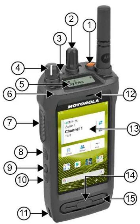
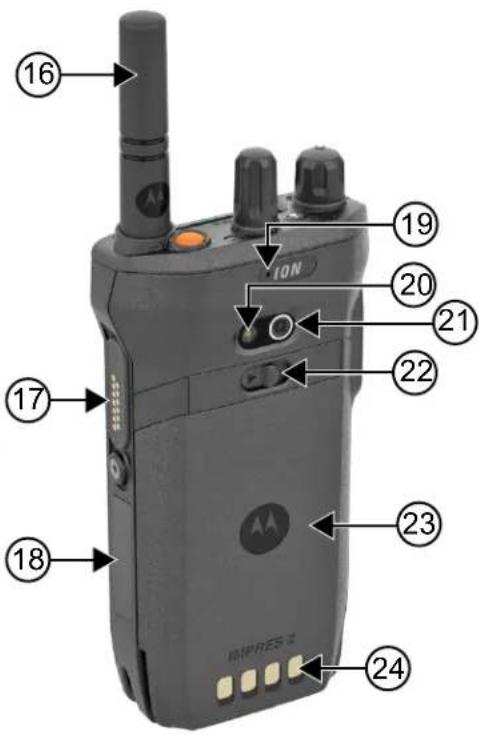
Table 3: Radio Overview
| Label Name Description | |
| 1 Emergency button Allows you to turn on or off the emergencies. | |
| 2 Channel Selector knob Allows you to select channel. | |
| 3 LED Indicator Provides operating status. | |
| 4 On/Off/Volume knob Allows you to turn the radio on or off and adjust volume. | |
| 5 Top Display Provides notification of an activity or event. | |
| 6 Holster Catch Feature Allows you to secure holster to the radio. | |
| 7 Push-to-Talk (PTT) button Allows you to execute voice operations (for example, Group Call and Private Call). | |
| 8 3-Dot Programmable Feature button | Programmable button of an assignable radio function. |
| 9 1-Dot Programmable Feature button | Programmable button of an assignable radio func-tion. |
| 10 2-Dot Programmable Feature button | Programmable button of an assignable radio func-tion. |
| 11 Holster Rail Provides guideline for the placement of holster and radio. | |
| 12 Front Microphone Allows your voice to be sent when PTT or voice oper-ations are activated. | |
| 13 Touchscreen The radio display screen. | |
| 14 Display Sleep/Wake button Allows you to put the radio to Sleep or on Wake mode. | |
| 15 Speaker Outputs all tones and audio that are generated by the radio (for example, features like keypad tones and voice audio). | |
| 16 Antenna Provides the needed RF amplification when transmit-ting or receiving. | |
| 17 Accessory Connector Allows you to connect accessories to your radio. | |
| 18 Device Labeling Area Area for adhesive label with a recommended size of 34.5 mm (length), 12.8 mm (width), and 1.3 mm at the corner for customization. | |
| 19 Rear Microphone Noise Cancellation Microphone. | |
| 20 LED Flash Provides flash light function. | |
| 21 Camera Allows you to take photos, videos, or scan QR code. | |
| 22 Battery Latch | Allows you to lock or unlock battery from the radio. |
| 23 Battery | Provides power source to your radio. |
| 24 Charging Contacts | Charging point for the battery. |
3.1
Programmable Buttons
You can program the programmable buttons as shortcuts to the following radio functions through RadioCentral (RC).

NOTE:
If you try to launch features that are not supported in your current radio mode, a negative indicator tone sounds.
Contact your dealer for more information.
Table 4: Assignable Radio Functions
| Function | Description |
| Active Site Search | Allows you to search for an active site. |
| Auto Network | Based on your radio network strength, the feature allows the radio to automatically switch between |
FunctionDescription
| Converged Broadband and Converged Land Mobile Radio (LMR). | |
| Broadband Network Allows you to switch between Converged Broadband and Converged LMR. | |
| Broadband PTT Allows you to switch between Broadband PTT mode and LMR mode. | |
| Call Alert Allows you to direct access to the contacts list and select the required contact to send a call alert. | |
| Channel Knob Allows you to change the channel. | |
| Contacts Provides direct access to the contacts list. | |
| Current Site Information Allows you to view current site information. | |
| Fall Alert Allows you to toggle the Fall Alert alarms to on or off. | |
| Flexible RX List Allows you to enable or disable a dynamic Rx list. Provides you with the flexibility to add or remove talkgroup members. | |
| High/Low Power Allows you to toggle between high and low power. | |
| Intelligent Audio Allows you to toggle intelligent audio to on or off. | |
| Keyboard Wedge - Barcode Scan Allows you to launch the Scandit Keyboard Wedge application. | |
| Manual Dial For Private Allows you to initiate a Private Call by entering the subscriber ID. | |
| Manual Site Roam Allows you to start the manual site search. | |
| Message Allows you to access the Text Message feature in Digital mode and MDC Message feature in Analog mode through the radio menu (applicable to Display model only). | |
| Mic AGC Allows you to toggle the internal microphone automatic gain control (AGC) to on or off. | |
| Monitor | Allows you to monitor a channel. |
| Neighboring Site Information | Allows you to access Neighboring Site Information. |
| Nuisance Delete | Allows you to temporarily remove an unwanted channel from the scan list, except the Selected Channel. The nuisance deleted channel will be restored into the scan list, for instance, when the radio is powered off and back on again. |
| One Touch Access | Allows you to direct access to the predefined call features. |
| Permanent Monitor | Allows you to monitor a selected channel for all radio traffic until function is disabled. |
| Privacy | Allows you to toggle the privacy to on or off. |
| Radio Check | Allows you to check if the radio is active in the system. |
| Function Description | |
| Radio Enable or Disable Allows a target radio to be remotely enabled or disabled. | |
| Radio Name Displays the radio alias on the radio display. | |
| Recent Calls Allow you to view recent calls. | |
| Repeater or Talkaround Allows you to toggle between using a repeater and directly communicating with another radio. | |
| Ring Alert Type Allows you to direct access the Ring Alert Type setting. | |
| Scan Allows you to toggle the scan to on or off. | |
| Site Lock Allows you to enable the site lock to search only in the current site or disable the site lock to search in other sites as well. | |
| Status Allows you to select the status list menu. | |
| Switch Speaker Allows you to toggle the external audio feature on and off. External Audio reroutes the speaker audio from the attached wired accessory to the internal speaker (applicable to LTE and LMR system audio). | |
| Tight/Normal Squelch Allows you to toggle between tight or normal squelch (applicable to Analog mode only). | |
| Toggle AF Suppressor Allows you to toggle the AF Suppressor feature to on or off (applicable to Digital mode only). | |
| Toggle Call Priority Level Allows you to enable your radio to enter Call Priority Level High or Normal. | |
| Trill Enhancement | Allows you to toggle the trill enhancement to on or off. |
| TX Interrupt Remote Dekey | Allows you to stop an on-going voice call by dekeying the transmitting radio or terminate the repeater call hang time to free up the channel. |
| Unassigned | Indicates that the button function has not yet assigned. |
| Voice Control Activation | Allows you to initiate Voice Control commands. |
| Voice Operating Transmission (VOX) | Allows you to toggle the VOX to on or off. |
| Zone Selection | Allows you to select from a list of zones. |
Table 5: Assignable Android Applications
| Application | Application Type | Description |
| Barcode Scan | Custom | Enables you to launch your own barcode scanning application. |
| Browser | Standard | Enables you to launch a web browser. |
| Photo | Standard | Enables you to launch a camera to take photos. |
| Video | Standard | Enables you to launch a camera to record videos. |
Application Application Type Description
Work Ticket Custom Enables you to launch your own work ticket application.

NOTE:
- The application type for Android applications can be standard or customized.
- Before configuring the Android applications to be launched using programmable buttons, the applications need to include the relevant Android intents based on the intended application functionality. For more details on intent definitions, see developer.motorolasolutions.com.
3.2
Voice Control
Voice Control allows you to manage your radio and perform information lookups using voice commands. This feature is purpose-built for better communication and is active when you press and hold the programmed Voice Control button and speak the commands. When there is an ongoing LTE call, you are unable to use this feature.

NOTE: Language in Voice Control feature is the same as the one configured in the Text to Speech feature. See Checking the Text to Speech Configured Language on page 97
You are able to operate the radio with your voice using the following commands.
Table 6: Voice Control Commands
| Feature Examples | |
| Zone and Channel To identify your current zone and channel, say the following commands:“Zone and channel”“What is my zone and channel”“Current zone and channel”“What is my current zone and channel” | |
| To change to a new zone and channel, say the following commands:“Zone, channel”“Zoneand channel”“Zone to, channel to”“Zone toand channel to”“Change zone to, channel to”“Change zone toand channel to”“Change zone to, channel”“Change to zone, channel”“Change to zoneand channel”“Go to zone, channel” | |
Feature Examples
| • “Go to zoneand channel”• “Switch zone to, channel to”• “Switch zone to and channel to”• “Switch to zone, channel”• “Switch to zone and channel”NOTE: To use Voice Control to change zones or channels, the Voice Control Name/TTS Announcement must be pre-configured in the RadioCentral (RC) software. Check with your dealer or system administrator to determine how your radio has been programmed. | |
| Zone To identify your current zone, say the following commands:• “Zone”• “What is my zone”• “Current zone”• “What is my current zone” | |
| Channel To identify your current channel, say the following commands:• “Channel”• “What is my channel”• “Current channel”• “What is my current channel” | |
| Volume To identify the volume level of your radio, say the following commands: | |
Feature Examples
| “Volume”“What is my volume”“Current volume” | |
| To change the volume level of your radio, say “Volume”. The available commands and their respective volume levels are as follows:“Low”, “min”, or “minimum” – 10%“Medium” – 50%“High”, “max”, or “maximum” – 100%“1” to “10” – 10% to 100% | |
| Battery To identify your battery level, say the following commands:“Battery”“What is my battery”“Battery check”“Battery level”“What is my battery level”“Battery status”“What is my battery status” | |
| Time To identify current time, say the following commands:“Time”“Current time”“Time check”“What is the time”“What time is it” | |
| Home Channel To change to your home channel, say the following commands:“Home channel”“Change to home channel”“Go to home channel”“Switch to home channel” | |
| Scan To start or stop scanning, say the following commands:“Start scan”“Stop scan”“Start scanning”“Stop scanning” | |
| Cancel Last Command To cancel your previous command, say “Cancel”.NOTE: Cancel command works within a five-second window after the last command. | |
Chapter 4
System Overview
System overview explains what type of systems and modes available in the radio.
4.1
Capacity Max
Capacity Max is MOTOTRBO control channel based trunked radio system.
MOTOTRBO digital radio products are marketed by Motorola Solutions primarily to business and industrial users. MOTOTRBO uses the European Telecommunications Standards Institute (ETSI) Digital Mobile Radio (DMR) standard, that is, two-slot Time Division Multiple Access (TDMA), to pack simultaneous voice or data in a 12.5 kHz channel (6.25 kHz equivalent).
4.2
Conventional Analog and Digital Modes
Each channel in your radio can be configured as a conventional analog or conventional digital channel.
Certain features are unavailable when switching from digital to analog mode and analog to digital mode, whereas some are available in both.
There are minor differences on how each feature works but they do not affect the performance of your radio.
4.3
IP Site Connect
This feature allows your radio to extend conventional communication beyond the reach of a single site by connecting to different available sites by using an Internet Protocol (IP) network.
When the radio moves out of range from one site and into the range of another, the radio connects to the repeater of the new site to send or receive calls or data transmissions. This is done either automatically or manually depending on your settings.
In an automatic site search, the radio scans through all available sites when the signal from the current site is weak or when the radio is unable to detect any signal from the current site. The radio then locks on to the repeater with the strongest Received Signal Strength Indicator (RSSI) value.
In a manual site search, the radio searches for the next site in the roam list that is currently in range but which may not have the strongest signal and locks on to the repeater.

NOTE: Each channel can only have either Scan or Roam enabled, not both at the same time.
Channels with this feature enabled can be added to a particular roam list. The radio searches the channels in the roam list during the automatic roam operation to locate the best site. A roam list supports a maximum of 16 channels, including the selected channel.

NOTE: You cannot manually add or delete an entry in the roam list. Contact your dealer for more information.
4.4
Capacity Plus
Capacity Plus is a cost effective and entry-level digital trunked system. It expands the capacity and extends the coverage for single and multi-sites. The single and multi-sites dynamic trunking offers better capacity and coverage.

NOTE: If you try to access a feature not applicable to Capacity Plus–Single-Site or Capacity Plus–Multi-Site by using a programmable button, you hear a negative indicator tone.
Capacity Plus-Single-Site
Capacity Plus–Single-Site is a single-site trunking configuration of the MOTOTRBO radio system, which uses a pool of channels to support hundreds of users and up to 254 groups.
This configuration allows your radio to efficiently utilize the number of available programmed channels while in Repeater Mode.
Your radio also has features that are available in conventional digital mode, IP Site Connect, and Capacity Plus.
Capacity Plus-Multi-Site
Capacity Plus–Multi-Site is a multi-channel trunking configuration of the MOTOTRBO radio system, combining the best of both Capacity Plus and IP Site Connect configurations. It is also known as Linked Capacity Plus.
It allows your radio to extend trunking communication beyond the reach of a single site, by connecting to different available sites which are connected with an IP network. It also provides an increase in capacity by efficiently utilizing the combined number of available programmed channels supported by each of the available sites.
When your radio moves out of range of one site and into the range of another, it connects to the repeater of the new site to send or receive calls or data transmissions. Depending on your settings, this is done automatically or manually.
Automatically
Your radio scans through all available sites when the signal from the current site is weak or unable to detect any signal and locks on to the repeater with the strongest RSSI value.
Manually
Your radio searches for the next site in the roam list that is currently in range which may not have the strongest signal, and locks on to it.
Any channel with Capacity Plus Multi-Site enabled can be added to a roam list. Your radio searches these channels during the automatic roam operation to locate the best site.

NOTE: You cannot manually add or delete an entry in the roam list.
4.5
Direct Mode or Dual Capacity Direct Mode
If within the customer's required coverage area, any system user can directly communicate with all of the other system users with just the output power of the transmitter in their portable or mobile radio, then a direct mode or dual capacity direct mode system can be used.
Direct Mode or Dual Capacity Direct Mode (DCDM) is direct radio-to-radio communication for systems that do not use a repeater. When radios operate in direct mode or dual capacity direct mode, the radios always transmit and receive on the same frequency. Direct mode and dual capacity direct mode provide similar services to the end users, with the exception that dual capacity direct mode is only available in digital mode,
MN006217A01-AK
Chapter 4: System Overview
and supports two simultaneous voice or data paths on a 12.5 kHz bandwidth channel while direct mode supports only one. Additionally, there are some minor differences. For example, dual capacity direct mode channels may not be used as GNSS revert channels.
The radios are not limited to one direct mode/dual capacity direct mode frequency. They can be programmed to have different frequencies, which are selectable with the channel selector knob.
Direct mode or dual capacity direct modes do not need over-the-air hang time for voice calls. The radio has an internal call ("talk back") timer. The channel access method used before the call timer expires is impolite, since the radio is still a member of an active call. This is independent of the Channel Access selection for call initiation (polite or impolite).
Chapter 5
Seamless Voice
Seamless Voice is a feature that allows you to stay connected to the radio network even when you are outside of the radio coverage. Seamless Voice uses broadband connectivity as a backup path to the LMR System. The Seamless Voice feature is supported in Capacity Max and Capacity Plus (Single-Site and Multi-Site) systems.
You are able to switch between networks automatically or manually. For Converged channel, if the Auto Network feature is enabled and both LMR and Broadband connections are available, your radio prioritizes the LMR connection.
The Broadband PTT application and Seamless Voice are mutually exclusive. You are required to uninstall the Broadband PTT application before using Seamless Voice.
For more information on the feature dependency, see MN008940A01, MOTOTRBO Ion Seamless Voice Provisioning Guide on https://learning.motorolasolutions.com/ion.
Seamless Voice can be used in the following features:
• Zone and Channel Selections
- Private Call ^1
- Group Call
- Call Alert ^1
• Emergency Operation
- Lone Worker
- Fall Alert (formerly known as Man Down) on page 86
• Transmit Interrupt (Supervisory Override) 1
5.1
Uninstalling Broadband PTT Application

NOTE:
Broadband PTT Application is not the official application name and is different depending on your region.
Verify the WAVE icon when you download the application from Google Play Store. Contact your dealer or administrator for more information.
Procedure:
- Upon turning on the radio, perform one of the following actions:
| Option Actions | |
| Uninstalling the Broadband PTT application from the Radio Control Notification | a. Use the WAVE service.b. At the received Radio Control notification, tap Uninstall. |
| Uninstalling the Broadband PTT application from the Radio Settings | a. From Settings, tap Apps & notifications→→ Un-install → OK.b. Swipe down the notification panel.c. Tap Uninstall on the Broadband PTT Service Failure notification. |
2. Power cycle your radio.

NOTE:
You are able to use the Seamless Voice feature after the power cycle.
Your radio automatically logs in and out of the WAVE and Converged WAVE channels when you turn on or off your radio.
5.2
Seamless Voice Authentication
Your radio automatically logs in and out of the WAVE and Converged WAVE channels when you turn on or off your radio.
When you have log in successfully, your radio shows Successfully contacted WAVE.
When you fail to log in, see the following scenarios:
Table 7: Log In Failure Scenarios
| Types of Failure Actions | |
| Activation Failure Contact your Corporate Administrator for new activation code. | |
| No WAVE Server | Contact your Corporate Administrator. |
| • Service Suspended | In the meantime, your radio shows a pop-up message. Perform one of the following actions: |
| • Account Deleted | |
| • Login Failures | • To switch to the LMR channel, tapSwitch. |
| • To remain on the channel, tapDismiss. | |
| No Network Connection Make sure your cellular or Wi-Fi is turn on in Settings. | |
5.3
Network Switch Settings
Your radio supports both Auto Network and Broadband Network in Converged channels.
The Auto Network switch allows you to enable the switching between LMR and WAVE networks automatically depending on the signal strength of the network.
The Broadband Network switch allows you to switch between LMR and WAVE networks manually.
For Converged Channels in LMR, you are allowed to toggle either Auto Network or Broadband Network to
on. The Converged LMR icon or Converged WAVE icon appears in the Radio Control Widget when the setting is enabled.

NOTE: This feature is not supported for LMR only and WAVE only channels.
5.3.1
Turning Auto Network Switch to On or Off
Turning Auto Network Switch to On
Procedure:
Perform one of the following actions:
| Option Actions | |
| Enabling Auto Network Switch with Menu Feature Launcher | a. From the Menu Feature Launcher Widget, tap More → Radio Network Set..b. Toggle Auto Network to on. |
| Enabling Auto Network Switch with Radio Quick Settings | a. From the Radio Control Widget, tap Radio Quick Settings.b. Toggle Auto Network to on. |
Turning Auto Network Switch to Off
Procedure:
Perform one of the following actions:
| Option Actions | |
| Disabling Auto Network Switch with Menu Feature Launcher | a. From the Menu Feature Launcher Widget, tap More → Radio Network Set..b. Toggle Auto Network to off. |
| Disabling Auto Network Switch with Radio Quick Settings | a. From the Radio Control Widget, tap Radio Quick Settings.b. Toggle Auto Network to off. |
5.3.2
Turning Broadband Network Switch to On or Off
Turning Broadband Network Switch to On
Prerequisites: Make sure you are in a Converged Channel. Turn off the Auto Network in order to enable Broadband Network.
Procedure:
Perform one of the following actions:
| Option Actions | |
| Enabling Broadband Network Switch with Menu Feature Launcher | a. From the Menu Feature Launcher Widget, tap → Radio Network Set..b. Toggle Broadband Network to on. |
| Enabling Broadband Network Switch with Radio Quick Settings | a. From the Radio Control Widget, tap b. Toggle Broadband Network to on. |
Result: When Broadband Network switch toggles to on, you are using the WAVE Network on Converged Channels.
Turning Broadband Network Switch to Off
Procedure:
Perform one of the following actions:
| Option Actions | |
| Disabling Auto Network Switch with Menu Feature Launcher | a. From the Menu Feature Launcher Widget, tap → Radio Network Set..b. Toggle Broadband Network to off. |
| Disabling Auto Network Switch with Radio Quick Settings | a. From the Radio Control Widget, tap b. Toggle Broadband Network to off. |
Result: When Broadband Network switch toggles to off, you are using the LMR Network on the Converged Channels.
5.4
Enable and Disable PTT Service
When you are in WAVE and Converged WAVE channels, your radio only receives Enable and Disable PTT service triggered by an authorized user. You are unable to initiate the Enable or Disable PTT service.
When the authorized user initiates Disable PTT, your radio shows the following indications:
- The top display shows No WAVE Server.
- The display shows Service Suspended pop-up message.
- If you press the PTT button, a negative tone sounds.
When the authorized user initiates Enable PTT, your radio shows PTT is enabled.
Chapter 6
Getting Started
This chapter provides instructions on how to prepare your radio for use.
6.1
Inserting or Removing MicroSD Card
Procedure:
- Slide the battery latch into unlock position.
- Remove the battery from the slot at the bottom of the radio.
- Remove the microSD card cover and the microSD card tray.
-
Perform one of the following actions:
-
To insert, place the microSD card into the tray.
- To remove, take the microSD card out from the tray.

NOTE: Only FAT32 microSD card format is supported. If you insert an unsupported microSD card, you are prompted to format the microSD card. Formatting leads to data erasure.
6.2
Inserting or Removing SIM Card

NOTE: This task is not applicable to eSIM.
Your radio supports private or public SIM card.
Procedure:
- Slide the battery latch into unlock position.
- Remove the battery from the slot at the bottom of the radio.
- Remove the SIM card cover and the SIM card tray.
-
Perform one of the following actions:
-
To insert, place the SIM card into the tray.
- To remove, take out the SIM card from the tray.
6.3
Attaching or Detaching the Battery
Attaching the Battery
Procedure:
- Fit the battery into the slot at the bottom of the radio.
- Push the top of the battery down until the latch snaps into place.
Detaching the Battery
Procedure:
- Slide the battery latch into unlock position.
- Remove the battery from the slot at the bottom of the radio.
6.4
Attaching or Detaching the Accessory Connector Cover
To prevent damage to the accessory connector, shield it with the connector cover when not in use.
Attaching the Accessory Connector Cover
Procedure:
- Insert the hooked end of the cover into the slot above the connector.
- Press the top of the cover down to seat it in the slot.
- Rotate the thumbscrew clockwise to tighten the cover.
Detaching the Accessory Connector Cover
Procedure:
- Rotate the thumbscrew counterclockwise until it disengages from the radio.
- Rotate outwards and lift the connector cover to disengage it from the radio.
6.5
Attaching or Detaching the Antenna
Attaching the Antenna
Procedure:
- Set the antenna in the receptacle.
- Turn the antenna clockwise.
Detaching the Antenna
Procedure:
- Turn the antenna counterclockwise.
- Remove the antenna from the receptacle.
6.6
Charging the Battery
Your radio does not show charging icon or LED indication on the front or top display during charging. The charging based estimation is with 25% granularity (5% 25%, 50%, 75%, 100%). The radio front display shows 50% charging when the radio powers up, and returns to normal battery percentage indicator after the synchronization completes.
Procedure:
- Turn off the radio.
- Place the radio in a Motorola Solutions approved charger.
natural_image
Black motorola device with antenna and front panel (no visible text or symbols on device body)The charger LED illuminates.

NOTE:
- If the charger LED blinks in red when charging, reinsert your radio.
-
If the charger detects the new IMPRES battery, it automatically starts initialization. Initialization is the first calibration and reconditioning of an IMPRES battery. For more information about Motorola Solutions approved charger, see Manual Part Number: MN006348A01 at https://learning.motorolasolutions.com/.
-
To remove the radio from the charger, pull the radio upwards.

NOTE:
- Your radio takes approximately six to ten seconds to update the battery information once the radio is removed from the charger.
- For more information, see Battery Information on page 62.
6.7
Turning the Radio On or Off
Turning the Radio On
Procedure:
Turn the On/Off/Volume knob clockwise until a click sounds.
Turning the Radio Off
Procedure:
Turn the On/Off/Volume knob counterclockwise until a click sounds.
6.8
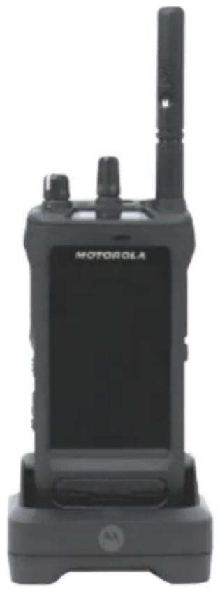
Holding Your Radio While Transmitting Audio
Procedure:
- When using high audio, hold your radio vertically with the top microphone 5–10 cm away from your mouth.
- Speak into the top microphone.

NOTE: Do not speak facing the bottom or the back of your radio.
- Listen through speaker.
- Keep the antenna at least 2.5 cm from your head and body.
Result:
The following shows the correct way of holding your radio while transmitting audio.
6.9
Adjusting the Volume
Procedure:
Perform one of the following actions:
- To increase the volume, turn the On/Off/Volume knob clockwise.
- To decrease the volume, turn the On/Off/Volume knob counterclockwise.

NOTE:
Your radio can be programmed to have a minimum volume offset where the volume level cannot be lowered past the programmed minimum volume.
When adjusting the volume, the top display illuminates.
Adjusting the volume actions is applicable for both Long Term Evolution (LTE) and Land Mobile Radio (LMR) volume control.
6.10
Activating eSIM
Prerequisites: Ensure your radio is connected to the Wi-Fi.
Procedure:
- From Settings, tap Network & Internet → Mobile network → Download a SIM instead? → Next.
- Aim your camera to the QR code of your eSIM.

NOTE: Ensure the QR code is captured in the box.
- Tap Activate → Done. The eSIM profile is activated.
- To connect using eSIM, turn off the Wi-Fi. NOTE: See Turning Wi-Fi On or Off on page 67.
6.11
Removing Camera Lens Protective Cover
Procedure:
Lift the protective film from the camera lens.
6.12
Using the Carry Holster
Inserting the Radio into the Carry Holster
Procedure:
- Insert the radio with the display screen facing the carry holster.
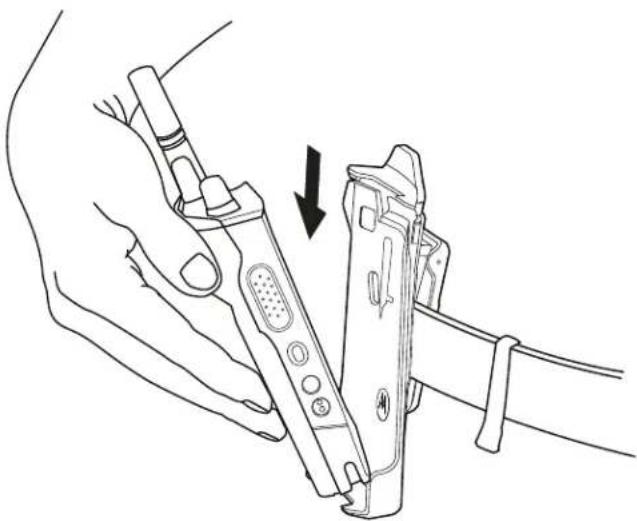
natural_image
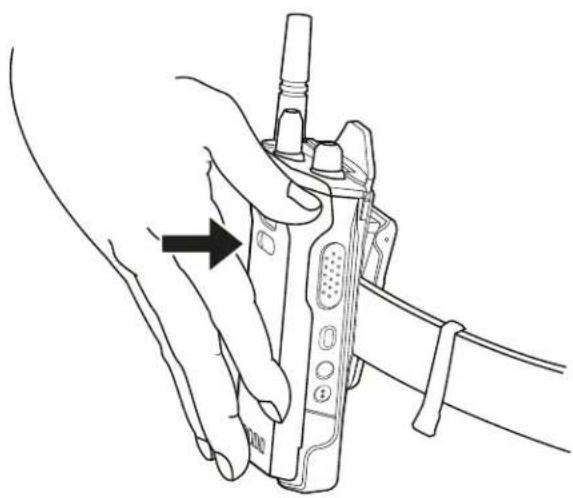
Line drawing of a hand holding a device with an arrow indicating the process (no text or symbols present)- Push the radio towards the carry holster until it clicks in place.
natural_image
Line drawing of a hand holding a walkie-talkie device with a black arrow pointing to the handle (no text or symbols present)Removing the Radio from the Carry Holster
Procedure:
- Press the tab to release the radio from the carry holster.
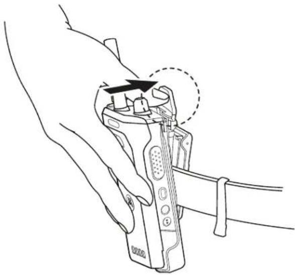
natural_image
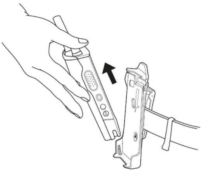
Line drawing of a hand holding a handheld device with an arrow indicating the process (no text or symbols present)- Remove the radio from the carry holster.
natural_image
Line drawing of a hand holding a handheld device with an arrow pointing to the device (no text or symbols present)6.13
On-Screen Keyboard Overview
Use the keyboard in portrait or landscape orientation to enter alphanumeric text on your radio. The keyboard supports auto-capitalization and word suggestions in the Messaging feature.
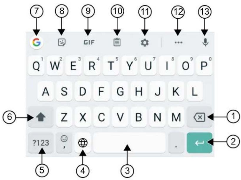
Table 8: On-Screen Keyboard Overview
| No. Name Description | |
| 1 Backspace To delete a character. | |
| 2 Enter To go to the next line. | |
| 3 Spacebar Tap to insert space. | Double-tap to insert a period. |
| 4 Globe To change the keyboard language. | NOTE:Only applicable if your radio has more than one language.If the user input character from the Android keyboard is not supported by the LMR system, the top display shows ? symbol for unsupported character. |
| 5 ?123 Tap to input numbers, punctuation, or symbols. | |
| 6 Caps Lock Tap to type in uppercase. | Double-tap for caps lock. |
| 7 Google Search Tap to perform Google search using Chrome. | |
| 8 Stickers Tap to access Stickers. | |
| 9 GIF Tap to access GIF. | |
| 10 Clipboard Text copied will automatically show here. | |
| 11 Settings | Tap to access Gboard Settings. |
| 12 More | Tap to view more features. |
| 13 Text-to-Speech | Tap to access Text-to-Speech. |

NOTE: Based on the language settings of your radio, you can tap and hold a character to input alternate characters.
6.14
Touchscreen Navigation
Table 9: Touchscreen Actions
| Action | Results |
| Tap | You can tap to perform the following actions:Select items on the screenType letters and symbols using the onscreen keyboardPress on-screen buttons |
ActionResults

Tap and hold You can tap and hold to perform the following actions:

natural_image
Hand icon with finger pressing a circular button (no text or symbols)- Drag an application on the home screen to move it to a new location or to remove it
- Create a shortcut of an application on the home screen
- At an empty area of the home screen, tap and hold to launch a menu to select wallpapers, widgets and Home settings
Swipe You can move your finger up, down, left, or right on the screen to perform the following actions:

natural_image
Illustration of two fingers interacting with a green star and circular target (no text or symbols)- Unlock the screen
• View additional home screens
• View additional application icons in the Launcher window
• View more information on an application screen
Double-tap You can tap twice on a webpage, map, or other screen to zoom in and out.

natural_image
Hand icon with green circular target and finger pointing at it (no text or symbols)Pinch In some applications, you can zoom in and out by placing two fingers on the screen and pinching them together (to zoom out) or spreading them apart (to zoom in).
ActionResults

natural_image
Hand icon pointing at a green star with circular background (no text or symbols)Chapter 7
Home Screen Overview
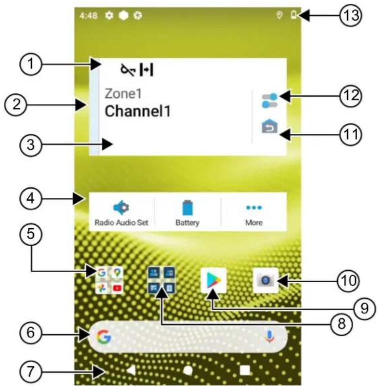
Table 10: Home Screen Overview
| No. Name Description | |
| 1 Channel Status Icons Provides information or status specific to the selected channel. | |
| 2 Light Bar Reflects the active call state of the radio. | |
| 3 Radio Control Widget Displays channel errors, trunking statuses, call states, and notifications.Allows you to change zone and channel from the home screen. | |
| 4 Menu Feature Launcher Widget | Displays the top three priority features provisioned in the RadioCentralTM.The More option appears if more than three priority features are provisioned in the RadioCentral.The More option contains all other programmed menu items. |
No. Name Description
| 5 Google Folder A folder that keeps all the Google applications. | |
| 6 Google Search bar A shortcut widget used to perform Google search using Google Chrome. | |
| 7 Back button Allows you to return to previous screen or exit application windows. | |
| Home button Allows you to return to home screen. | |
| Overview button Allows you to view a list of applications that are currently active on your radio. | |
| 8 M-Apps Folder M-Apps folder contains Motorola Solutions applications: | |
| M-ContactsM-DialerM-MenuM-MessengerM-Radio ControlM-Shift ManagerIf you open another application, M-Apps closes automatically.If you press the Overview softkey, M-Apps does not appear in Overview. | |
| 9 Google Play Google Play is your entertainment unbound. | |
| 10 Camera Allows you to take photos and videos. | |
| 11 Home Channel Revert Allows you to revert to the Home Channel or Talkgroup. | |
| 12 Radio Quick Settings | Allows you to quickly toggle the radio communication settings. The settings are channel specific. |
| 13 Status Bar | Status icons appear in the status bar to provide device status and feature notifications. |
7.1
Shift Manager Widget
The Shift Manager Widget displays the status of the radio with the Sign In ID. This widget allows you to send the operational status directly from the home screen.
Figure 1: Shift Manager Widget
My status
Meeting

You are able to sign in or sign out with your login ID and view the status in the widget. The status is only available when your current channel is using Capacity Max systems with status list assigned. When the sign in is successful, the first line of the widget displays the alias or ID of the user, whereas the second line of the widget displays the current status of the user.
When secure sign in is enabled, the user login ID or alias is not visible on the widget for security purposes.
7.1.1
User Login Feature
You can login the radio with your login ID and send status to your required contacts.
If the current user is not you, you can logout from the account and login to your own login ID.
7.1.1.1
Logging In to Automatic Registration Service
Procedure:
1. Tap

Shift Manager launcher → User Login.
- Perform one of the following actions:
- To log in with an existing ID, tap your ID.
- To log in with a new ID, tap Login with new ID →

- While sign in is in progress, tap Hide.
Result:
When login is completed, a message shows Login Success and the Shift Manager Widget shows the login ID.
If secure sign in is enabled, the login ID is not visible on the widget for security purposes.
7.1.1.2
Logging Out of Automatic Registration Service
Procedure:
1. Tap

Shift Manager Launcher →
-
Perform one of the following actions:
-
To clear the private data, tap Yes.
- To keep your private data, tap No.
7.1.2
Managing Operational Status
Procedure:

1. Tap
Shift Manager Launcher.
2. Select the available status.
Result:
The display shows Sending Status.
When the acknowledge is received, the display shows Acknowledge received and the status in the Shift Manager Widget is updated.
When the status is denied from the system, the displays shows Denied Status and the last acknowledged status remains in the Shift Manager Widget.

NOTE: When the status is denied, tap Tap to Retry in the Denied Status screen or Close to exit screen.
7.1.3
Sending Status
Procedure:
Perform one of the following actions:
| Option Actions | |
| Sending status to a contact | a. Tap Shift Manager Launcher → My Status →. |
| Sending status through M-Contacts | a. From the menu, tapM-Contacts.b. Tap→Status→. |
| Sending status through M-Dialer | a. From the menu, tapM-Dialer.b. Enter, and selectMore Options → Status → Close.c. Tap Status→. |
7.2
Status Indicators
Status Indicators explain the Icons and LED indicators used in your radio.
7.2.1
Status Icons
These icons appear at the status bar to provide device-specific information or status. There is a limit on the numbers of icons shown in the status bar. If the status bar is full, you might not get to see the icon even if the icon is active.

NOTE: If the following icons are not visible on your radio, enable it from the radio Settings.
Icon Name Description

(Front dis- play)
Battery Indicates the remaining battery level of the radio. The icon blinks when the battery level drops to 10% or lower.
| IconNameDescription | ||
| (Top display) | ||
| [CWBX] | Bluetooth On Bluetooth is on and ready for Bluetooth connection. | |
| [6V77] | Bluetooth Connected Bluetooth is connected to an external Bluetooth device. | |
| [K25T] | Location Location is enabled and its signal is available. | |
| [244T] | No SIM SIM card is not inserted or detected. | |
 | LTE/4G Mobile data service is enabled. | |
| [7704] | ||
 to [OX64] to [OX64] | LTE Network Strength The radio is connected to an LTE network. The number of bars represents the signal strength of the LTE network. | |
| [3D04] | LTE No Service The radio is not connected to an LTE network. | |
| [HOCK] | High-definition Voice The radio is capable of VoLTE (Voice over Long-Term Evolution) call. | |
| [WIBTZ] | Data Disabled The radio is connected to an LTE network but the data is disabled. | |
 | Notification (Top display only) | The radio receives notification of an activity or event. |
 | Time Indicates the current time. | |
 | Wi-Fi The radio is connected to a Wi-Fi network. The number of bars represents the signal strength of the Wi-Fi network. | |
 | Wi-Fi Hotspot Enabled | The radio created a Wi-Fi network that can be used by other devices. |
| [SWZK] | WAVE Service | WAVE Service is running. |
7.2.2
Radio Control Widgets Icons
These icons appear at the Radio Control Widget to provide information or status of Converged, LMR, and WAVE-specific features. The following shows the icon's look if the Dark theme is disabled. If the Dark theme is enabled, the icon's color will be inverted.
| Icon Name Description | ||
 | Broadcast Call^2 | The radio is receiving broadcast call from broad-casters. |
 | Call Priority High Allows the system to preempt one of the ongoing non-priority calls and initiate the requested high priority call when all channels are busy. | |
 | Converged LMR A converged channel that linked both LMR and WAVE. The icon indicates that the current talk-group is using the LMR transport. | |
 | Converged WAVE A converged channel that linked on both LMR and WAVE. The icon indicates that the current talk-group is using the Broadband transport. | |
 | Dynamic Group Num-ber Assignment (DGNA) | Allows the console to assign and remove a new talkgroup from your radio over the air. |
 | Direct The radio is configured for direct radio-to-radio communication in conventional operation. | |
 | High Volume Data The radio is receiving high volume data and the channel is busy. | |
 | Monitor The selected channel is being monitored in con-ventional operation. | |
 | Power Level Off – The radio is set at high power.On – The radio is set at low power. | |
 | Response Inhibit Prevent your radio from responding to any incoming transmissions. | |
 | Receiving The radio is receiving a call or data. | |
 to to  | Received Signal Strength Indicator (RSSI) | The number of bars represents the received signal strength of the current site in trunking and conven-tional mode. |
 | Roaming Site Roaming feature is enabled. | |
 | Transmit Inhibit The radio is blocking all transmissions. | |
 | Scan The radio is scanning a scan list. | |
 | Scan Priority 1or Scan Priority 2 | Blinking Dot- The radio is in Scan Priority 1.Steady Dot – The radio is in Scan Priority 2. |
 | Secure Blinking – The radio is receiving an encrypted voice call.Steady – The radio is operating in a secure channel. | |
 | Shared Frequency The radio is locked, allowing control channel to be shared. | |
 | Supervisory Override The radio is receiving supervisory override from talkgroup member that has supervisor role. | |
 | Transmitting The radio is transmitting a call or data. | |
 | Unsecure The radio is operating in an unsecure channel. | |
 | Voice Operating Transmission (VOX) | Allows you to initiate hands-free voice-activated calls on a programmed channel. |
7.2.3
LED Indicators
The LED indicates the types of behavior of your radio.
| LED Behavior Description | |
| Blinking Red Radio is transmitting in low battery state or indicating battery mis-match. | |
| Double Blinking Red Radio is receiving an emergency transmission. | |
| Rapidly Blinking Red Radio has failed the self-test upon powering up and is out of range. | |
| Solid Green Radio is powering up and transmitting. | |
| Blinking Green Radio firmware upgraded successfully. | |
| Double Blinking Green | Radio is receiving a privacy-enabled call or data. |
| Solid Yellow | Radio is entering Permanent Monitor state. |
| Blinking Yellow | Radio is performing scan. |
LED Behavior Description
Rapidly Blinking Yellow Radio is receiving Call Alert.
7.2.4
Backlight Indicators
The top display backlight indicates the types of behavior of your radio. You can configured the backlight timer settings to your preferred time or disable it.
Backlight Behavior Description
White When radio receives Over-the-Air activity, or user
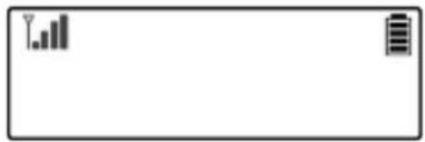
natural_image
Blank rectangular frame with two small icons: a bar chart and a battery symbol, no text or labels present.input such as turning the channel selector knob and after pressing the PTT or side button.
Orange When radio initiates or receives Emergency Alarm
or Call.

Red When radio is on the following critical alerts:

- Low Battery
- Out of Range
- Inability to establish a full connection with the system.
- Inability to authenticate or register with the system.
- Lost GPS signal or GPS function fails.
Green When radio receives the following calls:

natural_image
Green rectangular button with a small icon and a small grid bar (no text or symbols)- Private Call
- Call Alert
- Selective Call
- Entering Geofence
7.2.5
Lightbar Indicators
The Lightbar Indicator indicates the active call state of the radio.
Color Call State
Light Blue Open/Standby
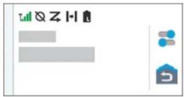
Yellow Receiving Call
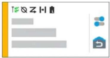
Red Transmitting Call
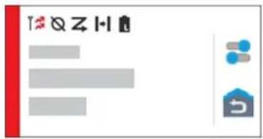
Gray Unprogrammed

natural_image
Simple diagram with a gray rectangle, two blue dots, and a house icon (no text or symbols)Chapter 8
General Radio Settings
This section explains the general settings that you can adjust on your radio.
8.1
Accessing Radio Settings
Procedure:
-
To access radio settings, perform one of the following actions:
-
From home screen, swipe up.
- Swipe down the notification panel.
2. Tap

Settings.
8.2
Creating Radio Settings as Shortcut in Home Screen
Procedure:
- Locate Settings.
- Long press and drag Settings to home screen.
8.3
Adjusting Display Brightness
Procedure:
Swipe down the notification panel and perform one of the following actions:
- To set a custom brightness level, drag the Brightness Slider.
- To automatically adjust the screen brightness based on the lighting conditions, tap Auto Brightness.
8.4
Turning On or Off Dark Theme
Procedure:
Perform one of the following actions:
- Swipe down the notification panel, tap Dark theme.
- From Settings, tap Display → Dark theme.
8.5
Setting the Clock
Procedure:
- From Settings, tap Clock.
- Perform one of the following actions:
| Option Actions | |
| Toggling 24-hour format on or off Tap Use 24-hour format. | |
| Toggling automatic time zone on or off Tap Set Automatic. | |
| Select time zone manually | a. Toggle Set Automatic to off.b. Tap Select Time Zone. |
8.6
Setting the Front Display Timer
This setting determines the period before the front display dims and turns off due to inactivity.
Procedure:
From Settings, tap Display → Front Display Timer →
8.7
Screen Lock
You can set your radio screen to lock automatically by specifying a pattern, PIN, or a password to keep your data secure.

IMPORTANT: If your radio screen lock option is set to None or Swipe, your data is not secured and can be accessed by anyone.
When your radio is on, you can lock your radio by pressing the Display Sleep/Wake button, and unlock by providing a pattern, PIN or a password.
If you did not specify a pattern, PIN, or a password you can also unlock your radio by swiping up the screen, or only by pressing the Display Sleep/Wake button if no locking option was set.
When your radio is locked, the cellular network signal, phone calls, notification of new messages, missed calls, and upcoming appointments are still available and can be received.
You can also set your radio to automatically lock after a specified time.
8.7.1
Unlocking Screen
Procedure:
- Press the Display Sleep/Wake button.
-
Swipe up the home screen.
-
Perform one of the following actions:
| Option Actions | |
| Unlocking the screen with pattern Draw the | specified pattern on the screen using your finger. |
| Unlocking the screen with a PIN or password | a. Enter your pin or password. b. Tap Save. b. Tap Save. |
8.8
Setting Languages
Procedure:
From Settings, tap Languages →
If the selected language is not supported by the Land Mobile Radio (LMR) setting, the selected language will revert to English whenever your radio operates in LMR setting.
8.9
Audio Settings
This section contains information on Audio Settings for Long Term Evolution (LTE) and Land Mobile Radio (LMR) system.
If there is concurrent audio coming from both LTE and LMR system, your radio prioritizes the audio from LMR system.
Depending on your radio Audio Settings when using a microphone, the LTE Audio may go on silent.
8.9.1
Turning Do Not Disturb On or Off
The Do Not Disturb setting allows you to mute alarms, reminders, events, messages, and calls.

NOTE: Ensure that the Do Not Disturb setting is disabled if there is a codeplug and firmware update plan.
Turning Do Not Disturb On
Procedure:
Perform one of the following actions:
- Swipe down the notification panel, tap Do Not Disturb.
- From Settings, tap Sound → Do Not Disturb → Turn On Now.
Turning Do Not Disturb Off
Procedure:
Perform one of the following actions:
- Swipe down the notification panel, tap Do Not Disturb.
- From Settings, tap Sound → Do Not Disturb → Turn Off Now.
8.9.1.1
Setting Do Not Disturb
Procedure:
- From Settings, tap Sound → Do Not Disturb.
- Perform one of the following actions:
| Option Actions | |
| Setting Do Not Disturb Exceptions for Calls | a. Tap Calls.b. Set the exception for the following options:Allow CallStarred CallsAllow Repeat Callers |
| Setting Do Not Disturb Exceptions for Messages | a. Tap SMS, MMS and messaging apps.b. Tap Allow messages. |
| Setting Do Not Disturb Exceptions for Other Features | a. Tap See all exceptions.b. Set the exception for the following options:Allow AlarmsPlay Media SoundsAllow Touch SoundsAllow RemindersAllow Events |
| Setting Restriction for Notifications | a. Tap Restrict Notifications.b. Set the restriction for the following options:No sound from notificationsNo visuals or sound from notificationsCustom |
| Setting Default Duration for Do Not Disturb | a. Tap Default Duration.b. Perform one of the actions:Tap Until you turn off.Tap and edit the.Tap Ask every time. |
8.9.2
Accessing Radio Audio Settings
Procedure:
-
Perform one of the following actions:
-
From the Menu Feature Launcher Widget, tap More → Radio Audio Settings.
-
From Settings, tap Sound → Radio Audio Settings.
-
To change the radio audio settings, select the following options:
- Audio Preference
- Default
○ Level 1
○ Level 2
○ Level 3 - Treble Boost
- Mid Boost
○ Bass Boost
- Noise Suppressor
○ Disabled
○ Basic
- Enhanced Auto (Default)
- AF Suppressor
- Intelligent Audio
- Mic AGC
8.9.2.1
Setting Audio Preference
Procedure:
-
Perform one of the following actions:
-
From the Radio Control Widget, tap 📄 Radio Quick Settings → Audio Preference.
-
From the Menu Feature Launcher Widget, tap More → Audio Preference.
-
Perform one of the following actions:
-
To disable the previous selected Audio Preference and return to the default factory settings, tap Default.
- For audio profiles that compensate noise-induced hearing loss in adults above 40 years old, tap Level 1, Level 2, or Level 3.
- If you prefer audio profiles with tinnier, more nasal, or deeper sounds, tap Treble Boost, Mid Boost, or Bass Boost.
8.10
Airplane Mode
When Airplane Mode is enabled, Bluetooth, Wi-Fi, and Cellular connections are automatically turned off. Land Mobile Radio (LMR) Rx and Tx operations are not blocked during Airplane mode.

NOTE:
- You must turn off the radio during flight to prevent radio frequency interference.
- You can turn on Bluetooth, GPS, and Wi-Fi connections manually during Airplane Mode.
8.10.1
Entering Airplane Mode
Procedure:
Perform one of the following actions:
- Swipe down the notification panel, tap Airplane Mode.
- From Settings, tap Network & internet → Airplane Mode → On.
Result:
Your radio shows the Airplane mode icon in the Status bar.
For Capacity Max, your radio displays an informative dialog message.
8.11
USB Desense
When your radio is connected to another device using a USB cable, any receiving and transmitting activities are disabled.
You will face the following scenarios:
- You can only control the volume using Volume knob.
- You cannot press the PTT button.
- You cannot tap the Menu Feature Launcher Widget.
For Capacity Max system, if you enable the airplane mode and disable the USB Desense, your radio displays the following indications:
- Airplane mode and USB desense informative dialog boxes.
- Airplane mode icon.
8.12
Battery
8.12.1
Viewing Battery IMPRES 2 Information
Procedure:
Perform one of the following actions:

• From Settings, tap Battery → Battery IMPRES Info.
- From the Menu Feature Launcher Widget, tap More → Battery Info.
Result:
Your radio display the battery conditions. For more information, refer Battery Information.
8.12.1.1
Battery Information
Battery information displays the current status of your battery. Depending on the battery conditions, your radio shows the following information.
| Battery Condition Information Display on Radio | |
| Good Condition | Remaining CapacityFirst UsedService LifeKit Number |
| Radio is inserted into the charger during ON state | Battery needs recondition |
| Battery Needs Recondition | |
| Wrong Battery | The top display shows WRONG BATT.Battery IMPRES info displays Wrong Battery.The display shows Wrong Battery notification.Upon powering up your radio, the display shows Wrong Battery dialog box. |
| Radio is turned on in the charger | Unknown Battery |
| Unknown | |
8.12.2
Setting Battery Saver
Procedure:

- From Settings, tap Battery → Battery Saver.
- Perform one of the following actions:
| Option Actions | |
| Setting a schedule for battery saver | a. Tap Set a schedule.b. Set the. |
| Toggling automatic battery saver off when fully charged | Toggle Turn off when fully charged. |
| Turning on battery saver manually Tap TURN ON | NOW. |
| Turning off battery saver manually Tap TURN OFF | NOW. |
8.12.3
Turning Battery Percentage On or Off
Turning Battery Percentage On
Procedure:
From Settings, tap Battery → On.
Result: The front radio display shows the current percentage of the battery.
Turning Battery Percentage Off
Procedure:
From Settings, tap Battery → Off.
Result: The current percentage of the battery on the front radio display disappears.
8.13
Performing Device Factory Reset
Factory reset allows you to erase all Android data and restore your radio to the original settings.
Procedure:
From Settings, tap System → Reset options → Factory Reset.
Your radio restarts.
Chapter 9
About Device
You can view details about your device and access Radio Advanced for more information.
You can view the following details in About Device:
- Device name
- SIM Status
- Radio Advanced
- Model & hardware
The following describes the available information in Radio Advanced:
Table 11: Radio Advanced Information
| Radio Advanced Information Description | |
| Certificates Provides information on available certificates in your radio. | |
| Internt of Things (IoT) Status Provides IoT connection status. | |
| Radio Information Provides the following information about your radio: | |
| • Radio Alias | |
| • Radio ID | |
| • Software Version | |
| • ESN-AP | |
| • Codeplug Version | |
| Regulatory Label Provides information about your radio regulatory label. | |
| Control Map Provides the following information about your radio buttons or knobs: | |
| • Side Button 1 | |
| • Side Button 2 | |
| • Side Button 3 | |
| • Orange Button | |
| • Rotary Knob 1 | |
| • Rotary Knob 2 | |
9.1
Accessing Getting Started Page
Procedure:
- From Settings, tap About Device → Getting Started Page.
-
Perform one of the following actions:
-
You can scan the QR code.
- You can tap on the Open in Browser link.
9.2
Accessing Radio Advanced
Procedure:
Perform one of the following actions:
- From the Menu Feature Launcher Widget, tap More → Info.
- From Settings, tap About Device → Radio Advanced.
9.2.1
Accessing Regulatory Label
Procedure:
-
Perform one of the following actions:
-
From the Menu Feature Launcher Widget, tap More → Info.
-
From Settings, tap About Device → Radio Advanced.
-
Select Regulatory Label.
9.3
Checking Hardware Version
Procedure:
Perform one of the following actions:
- Detach the battery from your radio and check for the hardware version.
- From Settings, tap About Device → Model & hardware → Hardware version.
NOTE: The ninth character in the hardware version represents the revision of the hardware.
Chapter 10
Connectivity
You can connect your radio to other devices, accessories, or network through different types of connectivity.
10.1
LTE
Long Term Evolution (LTE) is to extend the data coverage of the radio when the Wi-Fi connection is unavailable.
The following bands are available based on regions:
Table 12: Available Bands Based on Regions
| Region Type of Bands Bands Available | |
| North America Group (NAG) | LTE B2, B4, B5, B7, B12, B13, B14, B17, B30, B48 |
| 3G Not Available | |
| International LTE 1, 2, 3, 4, 5, 7, 8, 20, 28, 38, 39, 40, 41 | |

NOTE: Contact your dealer or administrator upon eSIM availability.
10.2
Wi-Fi Operation
Wi-Fi® is a registered trademark of Wi-Fi Alliance®. You can set up and connect Wi-Fi network to update your radio firmware, codeplug, language pack, and Voice Announcement.
Your radio supports the following Wi-Fi networks.
Wi-Fi Enhanced Open
A new WFA security standard for public networks which provides encryption and privacy on open, non-password-protected networks in areas such as cafes, hotels and airports.
WEP/WPA/WPA2/WPA3-Personal Wi-Fi network
Uses pre-shared key/password based authentication. Pre-shared key/password can be entered by using the menu or MDM.
WPA/WPA2/WPA3-Enterprise Wi-Fi network
Designed for enterprise networks and requires a RADIUS authentication server. Your radio must be pre-configured with a certificate if certificate-based authentication is deployed and client certificate verification is required.

NOTE: Configure your Wi-Fi system according to the latest industry security recommendations or use Enterprise Wi-Fi.
10.2.1
Turning Wi-Fi On or Off
Turning Wi-Fi On
Procedure:
Perform one of the following actions:
- Swipe down the notification panel, tap Internet → Wi-Fi → On.
- From Settings, tap Network & internet → Internet → Wi-Fi → On.
Result: Your radio shows a list of available networks.
Turning Wi-Fi Off
Procedure:
Perform one of the following actions:
- Swipe down the notification panel, tap Wi-Fi.
- From Settings, tap Network & internet → Wi-Fi → Off.
10.2.2
Accessing Network
Procedure:
- From Settings, tap Network & internet → Wi-Fi.
- Perform one of the following actions:
| Option Actions | |
| Connecting to network Tap . | |
| Adding new network | a. Tap Add network b. To set the network configuration, tap and expand Advanced options and set accordingly.c. Tap Save. |
| Editing network | a. Tap [0023] Settings  Edit Save. Edit Save. |
| Forgetting network Tap Forget. | |
| Installing Enterprise Wi-Fi Certificate | Tap Advanced Install network certification. |
10.2.3
Turning Wi-Fi Hotspot On or Off
Turning Wi-Fi Hotspot On
Prerequisites:
Perform one of the following actions:
- Connect your radio to the preferred Wi-Fi network.
- Insert a SIM card into your radio and enable the 4G network.

NOTE:
If the hardware version of your radio is revision A, Motorola Solutions recommends you to connect your radio to the preferred Wi-Fi network while turning on the Wi-Fi hotspot for the following reasons:
- To avoid hotspot connection interruption.
- To ensure that previously connected devices can automatically connect to your radio Wi-Fi hotspot.
- Always adopt hotspot security best practices when using hotspot.
For more information on procedure for checking the hardware revision, see Checking Hardware Version on page 65.
Procedure:
Perform one of the following actions:
- Swipe down the notification panel and tap Hotspot.
- From Settings, tap Network & internet → Tethering → Wi-Fi hotspot → On.
Turning Wi-Fi Hotspot Off
Procedure:
Perform one of the following actions:
- Swipe down the notification panel and tap Hotspot.
- From Settings, tap Network & internet → Tethering → Wi-Fi hotspot → Off.
10.2.4
Editing Wi-Fi Hotspot Configuration
Procedure:
- From Settings, tap Network & internet → Tethering → Wi-Fi hotspot.
- Perform one of the following actions:
| Option Actions | |
| Naming the hotspot | a. Tap Hotspot name.b. Enter your preferred hotspot name.. |
| Selecting hotspot security type | Tap Security →. |
| Setting the hotspot password | a. Tap Hotspot password.b. Enter your preferred password. |
| Selecting AP Band Tap AP Band →. | |
| Setting your radio to turn off hotspot automatically | Tap Turn off hotspot automatically.[IMAGE]NOTE: When there are no devices connect to your radio hotspot for a period of time, the hotspot automatically turns off. |
10.3
Bluetooth®
This feature allows your radio to connect to any Bluetooth enabled device through Bluetooth connection.
Your radio supports Bluetooth connections to Commercially available Off-The-Shelf (COTS) headsets with HSP profiles as well as MSI BLE GATT accessories such as WM500 Corona RSM and EP910w PTT headset. Simultaneous connections to Bluetooth headsets are not supported.
The Bluetooth operates with a range of 10 meter (32 feet) line of sight or better. The Bluetooth function of your radio has a typical power of 4 dBm.
This is an unobstructed path between your radio and your Bluetooth enabled device. For high degree of reliability, Motorola Solutions recommends to not separate the radio and the Bluetooth enabled device.
If the voice and tone quality gets distorted or unclear, place your radio and the Bluetooth enabled device close to each other to re-establish clear audio reception.

NOTE:
- Use the latest Bluetooth accessories (v5.0 and above) for enhanced connection security.
- Always adopt Bluetooth security best practices when using Bluetooth devices.
10.3.1
Turning Bluetooth Mode On or Off
Turning Bluetooth Mode On
Procedure:
Perform one of the following actions:
- Swipe down the notification panel, tap Bluetooth.
- From Settings, tap Connect devices → Connection preferences → Bluetooth → On.
Turning Bluetooth Mode Off
Procedure:
Perform one of the following actions:
- Swipe down the notification panel, tap Bluetooth.
- From Settings, tap Connect devices → Connection preferences → Bluetooth → Off.
10.3.2
Connecting to Bluetooth Devices
Procedure:
- From Settings, tap Connected devices.
- Perform one of the following actions:
| Option Actions | |
| Connecting to an existing device | a. To search for nearby devices, tapConnection preferences → Bluetooth → Onb. Tap→ Connect. |
| Connecting to an existing device that has been cleared pairing from the device itself | a. Tap→ Disconnectb. Tap→ Forget.NOTE: You need to disconnect then forget the device from the connected device list to pair with the radio again.c. To search for nearby devices, tapConnection preferences → Bluetooth → Ond. Tap Pair new device →Connect. |
| Connecting to a new device | a. To search for nearby devices, tapConnection preferences → Bluetooth → Onb. Tap Pair new device →Connect. |

NOTE: If the Bluetooth Pairing PIN feature is enabled, verify that the codes are correct before you begin pairing.
10.3.3
Connecting to Personal Area Network Accessories
Procedure:
- From Settings, tap Network & internet → Tethering.
- To turn on Bluetooth tethering, tap Bluetooth tethering.
- From the Tethering screen, go back to Settings and tap Connected devices.
-
Wait for your Personal Area Network (PAN) accessory to trigger the pairing with your radio.
-
Once the pairing pop-up message appears, tap pair.

NOTE: To ensure a successful connection between your radio and the PAN accessory, avoid manually connecting the PAN accessory from your radio menu. Once the PAN accessory is undocked, the PAN accessory automatically connects to your radio.
10.3.4
Disconnecting from Bluetooth Devices
Procedure:
From Settings, tap Connected devices → Connection preferences → Bluetooth →
10.3.5
Forgetting Bluetooth Devices
Prerequisites: Disconnect your radio from the
Procedure:
From Settings, tap Connected devices →
Postrequisites: Clear the required connected devices from your Bluetooth accessories.
10.3.6
Viewing Device Details
Procedure:
From Settings, tap Connected devices →
10.3.7
Editing Device Names
Procedure:
From Settings, tap Connected devices →
Result:
The display shows Device Name Saved.
10.3.8
Bluetooth Profiles
Your radio supports a wide range of Bluetooth services.
Table 13: Bluetooth Profiles
| Profile Description |
| Dial-Up Networking (DUN) Provides access to the Internet and other dial up services over Bluetooth. |
| Generic Access Profile (GAP) This profile defines how Bluetooth enabled devices can make themselves available and how two devices can communicate directly with each other. |
| Generic Attribute Profile (GATT) Allows profile discovery and description services for Bluetooth Low Energy protocol. |
| Headset Profile (HSP) Provides support for the popular Bluetooth head-sets to be used with mobile phones with ability to ring, answer a call, hang up, and adjust the volume. |
| Object Push Profile (OPP) Allows the device to send objects such as images over Bluetooth. |
| Personal Area Network (PAN) Allows the device to share Internet connection with another device (for example a laptop) and to access the Internet shared by another device (for example a Bluetooth enabled phone). |
Chapter 11
Basic Radio Operation
This section explains the basic operations that you can perform on your radio.
11.1
Responding to Notifications
Procedure:
-
Swipe down the notification panel and perform one of the following actions:
-
To respond to a notification, tap the assigned action message.
- To clear all notifications, tap Clear All.

NOTE: You are unable to view the notifications once it is cleared.
- To exit notification panel, swipe up.
11.2
Managing Home Screen Widgets

NOTE: The home screen supports up to two widgets per screen only.
Procedure:
Perform one of the following actions:
| Option Actions | |
| Adding widgets to home screen | a. Tap and hold an empty space on the home screen.b. Tap widgets.c. Tap and hold the. d. Drag theto the. |
| Moving widgets within home screen | a. Tap and hold the.b. Drag theto the. |
| Moving widgets to the next screen | a. Tap and hold the.b. Drag theto the right of the screen.c. Release theto the. |
| Deleting widgets from home screen | a. Tap and hold the. b. Tap remove. |
11.3
Zone and Channel Selections
A zone is a group of channels. You can program each channel with different features that support different groups of users.
For non-Seamless Voice, in the Select Zone screen, you will see a list of LMR only channels.
For Seamless Voice, the types of channels are distinguished by the text headers in Select Zone screen. LMR only channels and Converged channels are under the LMR ZONES. For WAVE only channels, it is located under WAVE ZONES.
Figure 2: Select Zone Screen for Seamless Voice
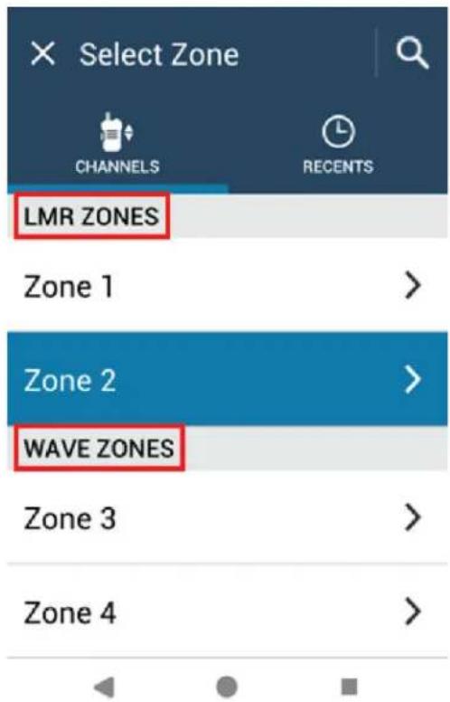

NOTE: For WAVE only channels, all LMR features are disabled.
Table 14: Number of Supported Zones and Channels
| Network Zones Channels Channels per Zone |
| LMR 250 1000 160 |
| WAVE 6 96 16 |
11.3.1
Selecting Zone
Procedure:
Perform one of the following actions:
- To select a zone, tap Radio Control Widget → Current Zone →
→ . - To select a zone from Recent tab, tap Radio Control Widget → Recent →
.
- To search for zone, More → Ch Search →
11.3.2
Selecting Channel
Procedure:
Perform one of the following actions:
- To select a channel, tap Radio Control Widget →
. - To select a channel from Recent tab, tap Radio Control Widget → Recent →
.
• To search for channel, tap

More →

Ch Search →
- To select a channel using the Channel Selector knob, rotate the Channel Selector knob to the required position.
11.3.2.1
Channel Error Messages
If there is a channel error, your radio displays the following error messages on the Radio Control Widget.
Type Description
| Unprogrammed The mode is set to an unprogrammed channel. | |
| Fail 001 | The selected channel is assigned to an incorrect frequency band. |
11.4
Talkaround
This feature allows you to continue communicating when your repeater is non-operational, or when your radio is out of range from the repeater but within the talk range of other radios.
The talkaround setting is retained even after powering down.
11.4.1
Toggling Between Repeater and Talkaround Mode
Procedure:
Perform one of the following actions:
• From the Radio Control Widget, tap

Radio Quick Settings → Repeater or Talkaround.
• From the Menu Feature Launcher Widget, tap

More → Repeater or Talkaround.
- Press the programmed Repeater or Talkaround button.
11.5
Power Level
This feature allows you to reduce the transmit power level for a specific case that requires a lower power level.
The reduced transmitted power level does not affect the receiving performance of your radio nor diminish the data functionality of the radio.
Low power level enables a shorter transmitting distance and helps conserve power.
High power level enables a longer transmitting distance.
11.5.1
Setting Power Levels
Procedure:
Perform one of the following actions:

- From the Radio Control Widget, tap
Radio Quick Settings → Power.
- From the Menu Feature Launcher Widget, tap

More → Power.
11.6
Setting LED Indicator
Procedure:
From the Menu Feature Launcher Widget, tap

re → LED Indicator.
11.7
Setting Squelch Levels
Procedure:
-
Perform one of the following actions:
-
From the Radio Control Widget, tap Radio Quick Settings → Squelch.
-
From the Menu Feature Launcher Widget, tap More → Squelch.
-
Perform one of the following actions:
-
For a normal squelch level, tap Normal.
- To filter out unwanted calls or background noise, tap Tight.
11.8
Toggling the Controls and Buttons Tones On or Off
Procedure:
- From the home screen, tap More.
- To toggle the controls and buttons tones on or off, tap Tones.
Chapter 12
Types of Radio Calls
There are several ways that you can make a call with your radio depending on the types of calls
Call Type LMR Only Converged WAVE Only
| All CallAn All Call is a call from an individualradio to every radio on the site orevery radio at a group of sites. All Callis used to make important announcement. | √ | ✕ | ✕ |
| Broadcast CallA Broadcast Call is a one-way voicecall from any user to an entire talk-group. The Broadcast Call feature al-lows only the call initiating user totransmit to the talkgroup, while therecipients of the call cannot respond. | √ | √ | √ |
| Call AlertCall Alert paging enables you to alertthe recipient to call you back whenthey are able to do so. Call Alert isapplicable for subscriber aliases orIDs only. | √ | √3 | √ |
| Group CallA Group Call is a point-to-multipointcall operation. Your radio must beconfigured as a member of the groupfor you to communicate with eachother. | √ | √ | √ |
| Open Voice Channel Mode (OVCM)CallAn OVCM Call allows a radio thatis not preconfigured to work in a par-ticular system to both receive andtransmit during a group or individualcall. | √ | ✕ | ✕ |
| Private CallA Private Call is a call from an indi-vidual radio to another individual ra-dio. There are two types of Privatecall in LMR which are: | √ | √3 | √ |
Call Type LMR Only Converged WAVE Only
- Off Air Call Set-Up (OACSU)
- Full Off Air Call Set-Up (FOAC-SU)
Selective Call
A Selective Call is a call from an individual radio to another individual radio. It is a Private Call on an analog system.


Unaddressed Call
An Unaddressed Call is a group call to one of the 16 predefined group IDs.


12.1
Making Calls
Procedure:
To make calls, perform one of the following actions:
| Option Actions | |
| Making calls from Contact list | a. From the menu, tap ^ ontacts→ ^ ontacts→ ^ II.b. To start the call, press and hold the PTT button.c. To end the call, tap End. II.b. To start the call, press and hold the PTT button.c. To end the call, tap End. |
| Making calls using dialer | a. From the menu, tap ^ ontacts→Floating Action Button → Dialer.b. Enter the.c. TapMore →.d. To start the call, press and hold the PTT button.e. To end the call, tap End.NOTE: This is not applicable to WAVE mode. ontacts→Floating Action Button → Dialer.b. Enter the.c. TapMore →.d. To start the call, press and hold the PTT button.e. To end the call, tap End.NOTE: This is not applicable to WAVE mode. |
| Making calls from Recent Calls | a. From the menu, tap More → RecentCalls →→Call.b. To start the call, press and hold the PTT button.c. To end the call, tap End. |
| Making WAVE Private Call from the Quick Action icon | a. From the menu, tap M-Contactsb. Tap and hold the Quick Action.c. Tap cll.d. To start the call, press and hold the PTT button.e. To end the call, tap End. |
| Making calls using Channel Knob and PTT button | a. To select a channel with an active ID or alias, toggle the Channel Selector knob.b. To start the call, press and hold the PTT button.c. Wait for the Talk Permit Tone to end, and speak into the microphone.d. To listen, release the PTT button. |
12.2
Responding to Calls
Procedure:
Perform one of the following actions:
- To speak, press and hold the PTT button.
- To listen, release the PTT button.
• To decline a call, tap Dismiss.
• To end an ongoing call, tap End.
Chapter 13
Emergency Operation
Emergency Alarms are used to indicate critical situations. You can initiate an Emergency Alarm at any time even when there is activity on the current channel.
You can only assign one type of Emergency Mode to the Emergency button for each channel. Your radio supports the following Emergency Modes:
Table 15: Emergency Modes
| Emergency Mode Description | |
| Emergency Alarm4 | An Emergency Alarm is not a voice call. This alarm is an emergency notification sent to radios that are programmed to receive them. |
| Emergency Alarm with Call | Your radio transmits an Emergency Alarm. When the Emergency Alarm is ac- knowledged, the group of radios can communicate over the assigned emergen- cy channel. Press and hold the PTT button to talk. |
| Emergency Alarm with Voice to Follow | Your radio transmits an Emergency Alarm. When the Emergency Alarm is ac- knowledged, your radio microphone is automatically activated which is known as Hot Mic. Hot Mic allows you to communicate with the group of radios without pressing the PTT button.[7705]NOTE:If the Emergency Cycle Mode is enabled, repetitions of Hot Mic and receiving period are made for a programmed duration.If you press and hold the PTT button during the programmed Hot Mic receiving period, your radio proceeds to make a call and stops Hot Mic receiving period timer. Your radio remains in emergency mode. Once PTT button is released, Hot Mic receiving period timer restarts.If the Emergency Alarm request fails, the radio does not retry to send the request, and enters the Hot Mic directly. |
| Silent Emergency Alarm4 | Your radio transmits an emergency notification without any audio or visual indi- cators. |
| Silent Emergency Alarm with Call4 | Your radio transmits an emergency notification without any audio or visual indi- cators. Your radio suppresses all audio and visual indicators of the emergency until you press and hold the PTT button to talk. |
| Silent Emergency Alarm with Voice to Follow4 | Your radio transmits an emergency notification without any audio or visual indi- cators. When the Emergency Alarm is acknowledged, the Hot Mic is activated. You can communicate with the group of radios without pressing the PTT button.NOTE:The indicators only appear when you press the PTT button. |
Your dealer can set the Emergency On or Off function and button-press duration of the Emergency button. Contact your dealer for more information.
Your dealer can program the Emergency Search tone. When the tone is programmed, the Emergency Search tone sounds. The tone mutes when your radio transmits or receives voice, and stops when your radio exits Emergency mode.
13.1
Sending Emergency Alarms
Procedure:
Press the programmed Emergency On button.
Result:
If the alarm is successfully sent, your radio shows the following indications:
• The Emergency tone sounds.
- The display shows Acknowledge Received and exited the Emergency Alarm.
If the alarm is unsuccessful after all retries, your radio shows the following indications:
- A negative tone sounds.
- The display shows No Acknowledge and exited the Emergency Alarm.

NOTE: For Converged Setup in Capacity Plus (Single-Site and Multi-Site) systems, the radio that is configured to provide ACK to an Emergency Alarm are always in the LMR network.
13.2
Sending Emergency Alarms with Call
Procedure:
- Press the programmed Emergency On button.
If the alarm is successfully sent, your radio shows the following indications:
• The Emergency tone sounds.
- The green LED blinks.
- The display shows Acknowledge Received.
If the alarm is unsuccessful after all retries, for Converged WAVE and WAVE only channel, the Radio Control Widget shows Emergency Fail and the top display shows EMER FAIL.
- To call, press and hold the PTT button.
- Wait for the Talk Permit Tone to end, and speak into the microphone.
- To listen, release the PTT button.
If your radio does not detect voice activity for a predetermined period, the call ends.
Result:

NOTE: For Converged Setup in Capacity Plus (Single-Site and Multi-Site) systems, the radio that is configured to provide ACK to an Emergency Alarm are always in the LMR network.
13.3
Sending Emergency Alarms with Voice to Follow
Procedure:
- Press the programmed Emergency On button.
If the alarm is successfully sent, the Emergency tone sounds and Hot Mic is activated.
If the alarm is unsuccessful after all retries, for Converged WAVE and WAVE only channel, the Radio Control Widget shows Emergency Fail and the top display shows EMER FAIL.
- Speak into the microphone without pressing the PTT button.
Your radio automatically stops transmitting when:
- The cycling duration between hot mic and receiving calls expires if Emergency Cycle Mode is enabled.
- The hot mic duration expires if Emergency Cycle Mode is disabled.

NOTE: For Converged WAVE and WAVE only channels, the hot mic duration is unable to configure.
13.4
Receiving and Responding to Emergency
When you receive an Emergency, your radio shows the following indications:
- A tone sounds.
- The red LED blinks.
- For LMR and Converged LMR channel, received Emergency Alarm Received notification shows sender's information including ID, zone, channel, and talkgroup.
- For Converged WAVE and WAVE only channel, received Emergency Alarm Received notification shows sender's information including ID and talkgroup.
- The Emergency notification appears and is added to the Recent Calls.
- The Radio Control Widget shows Emergency Alarm Received and the ID of the sender.
- The top display shows EA RECEIVED and ID of the sender.
Procedure:
Perform one of the following actions:
| Option Actions | |
| Dismissing the Emergency | Tap DISMISS on the notification. |
| Viewing the Emergency details | Tap More → Recent Calls →. |
| Calling back | a. Tap  More → Recent Calls →.b. Tap and hold the Quick Action.c. Tapd. To start the call, press and hold the PTT button.e. To end the call, tap End. More → Recent Calls →.b. Tap and hold the Quick Action.c. Tapd. To start the call, press and hold the PTT button.e. To end the call, tap End. |

NOTE: If you receive an Emergency from a sender with a different zone or channel, the information in the Recent Calls will be grayed out and unable to call back.
13.5
Exiting Emergency Mode
Your radio automatically exits emergency mode when you are having the following scenarios:
- An acknowledgment is received from the system (for emergency alarms only).
- All retries to send the alarm are exhausted.
- Turning off your radio. When you turn on your radio, the emergency will not reinitiate automatically.
Procedure:
Perform one of the following actions:
- Press the programmed Emergency Off button.
- If you receive emergency notification, tap CANCEL YES
Result:
If you exited the Emergency successfully, your radio shows the following indications:
- The tone ceases.
- The red LED extinguishes.

NOTE: If you exit the emergency mode while you receiving emergency alarm, The canceled emergency record populates the Recent list.
13.6
Emergency Remote Actions
The Authorized user or Console admin can initiate or cancel the Emergency Alarm remotely depending on the types of network system.
For Converged WAVE and WAVE only channels, the Authorized user with Broadband PTT application can initiate and cancel the emergency remotely, your radio shows a pop-up message indicating the Emergency Alarm is turned on or cancelled by the name of the Authorize user.
For WAVE only and Capacity Max channels, if your radio is currently receiving an emergency alarm and the Authorized user or Console admin cancels the emergency alarm, you can view the emergency cancelled logs in the Recent Calls.
For Capacity Max, the Console admin can cancel the emergency remotely, your radio shows a pop-up message indicating the Emergency Alarm is cancelled by console.
Chapter 14
Fall Alert (formerly known as Man Down)
The Fall Alert feature (formerly known as Man Down) enables your radio to alert others when you are in danger.
If your radio tilts at a specified angle, is moving, or is stationary for a time, it prompts you with an Alert Tone. If you do not respond to the prompt before the predefined reminder timer expires, your radio automatically sends an Emergency Alarm or Emergency Call.
To prevent your radio from sending an Emergency Alarm or Emergency Call, you can take the following measures:
- For Tilt Alarm, you must restore the radio to the vertical position.
- For Movement Alarm, you must stop your radio from moving.
- For Anti-Movement Alarm, you must move your radio.
If more than one Fall Alert Alarm is enabled, your radio plays the Alert Tone when it detects the first movement violation.

NOTE:
Fall Alert Alarms are not supported when operating in Fallback Mode.
This feature is supported in LMR only channels and Converged channels.
14.1
Turning the Fall Alert Feature On or Off
Turning the Fall Alert Feature On
Procedure:
- From the Radio Control Widget, tap

Radio Quick Settings.
- Toggle Fall Alert to on.
Turning the Fall Alert Feature Off
Procedure:
- From the Radio Control Widget, tap

Radio Quick Settings.
- Toggle Fall Alert to off.
14.2
Exiting Fall Alert
Procedure:
To exit Fall Alert, tap Cancel.
Chapter 15
Lone Worker
This feature prompts an emergency if there is no user activity (button press or channel selector activation) for a predefined time.

NOTE:
This feature is supported in LMR only channels and Converged channels.
When there is no user activity for a predefined time, the radio prewarns you using an audio indicator and on-screen notification on both front and top display once the inactivity timer expires. You can cancel the notification and the timer for lone worker resets. The wake-up and sleep button, and touch interface do not reset the timer.
If there is no acknowledgment from you before the predefined reminder timer expires, the radio initiates an emergency condition as programmed by the dealer.
Chapter 16
Privacy
This feature prevents eavesdropping by unauthorized users on a channel by the use of a software-based scrambling solution. The signaling and user identification portions of a transmission are clear.
Your radio must have privacy enabled on the channel to send a privacy-enabled transmission, although this is not a requirement for receiving a transmission.
Some radio models may not offer Privacy feature, or may have different configuration. Contact your dealer for more information.

NOTE:
Only one type of privacy can be assigned at a time.
This feature is not applicable in Citizens Band channels that are in the same frequency.
The following table describes the type of privacy and the settings that appear on your radio.
Table 16: Privacy Types and Settings
| Type Setting | |
| AES Privacy | AES Priv |
| Basic Privacy | Privacy |
| Enhanced Privacy | Enhanced Privacy |
16.1
Turning Privacy On or Off
Procedure:
Perform one of the following actions:

- From the Radio Control Widget, tap Radio Quick Settings → Privacy.
- From the Menu Feature Launcher Widget, tap More → Privacy.
- Press the programmed Privacy button.
Result:
If privacy is turned on, your radio shows the following indications:
- The top display momentarily shows PRIVACY ON.
- The secure icon appears in the top display and Radio Control Widget.
If privacy is turned off, your radio shows the following indications:
- The top display momentarily shows PRIVACY OFF.
- The secure icon disappears from the top display and Radio Control Widget.
Chapter 17
Contacts Settings
The contacts are defined by the network settings. The Contacts Settings provides an address book function on your radio that supports LMR contacts, WAVE contacts, and Converged contacts. Each entry corresponds to an ID for making calls. The entries are alphabetically sorted and different for LMR and WAVE mode.
Each entry within Contacts contains the following information:
- Call Alias
- Call ID
- Call Type
- System ID
When your radio is in LMR mode, the contact list will show LMR and Converged contacts. When your radio is in WAVE mode, the contact list will show WAVE and Converged contacts.
In LMR mode, your radio supports Call, Call Alert, Remote Monitor, Message, Status, and Radio Check. See Accessing Contact Settings on page 91.
In WAVE mode, the Floating Action Button (FAB) is not supported. Your radio only supports WAVE
Private Call and WAVE Call Alert. You can launch the features by tapping and holding the Quick Action. Each contacts displayed the current available status such as Available, Unavailable, or Do Not Disturb (DND).
The Converged contact number changes when you switch between the modes.
17.1
Contacts Overview
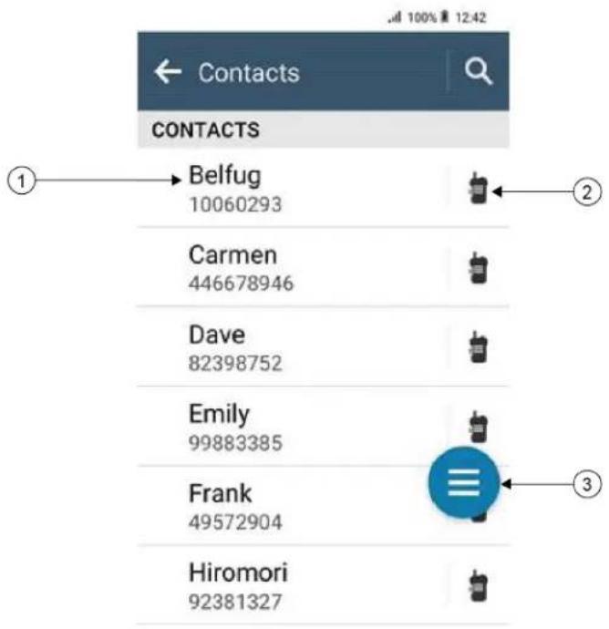
Table 17: Converged LMR or LMR only Overview
| Label Name Description |
| 1 Saved Contacts You radio display the numbers and names of saved contacts. |
| 2 Quick Action Allows you to perform the assigned radio function. |
| 3 Floating Action Button (FAB) Allows you to access contact options. |
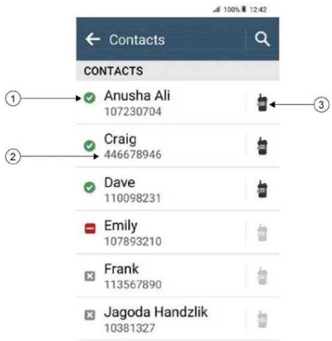
Table 18: Converged WAVE or WAVE only Overview
| Label Name Description |
| 1 Contact Status You radio display the contact status such as available, unavailable, and do not disturb (DND). |
| 2 Saved Contacts Your radio displays the numbers and names of saved contacts. |
| 3 Quick Acton Allows you to perform the assigned radio function. |
17.2
Accessing Contact Settings
Procedure:

- From the menu, tap M-Contacts.
- Perform one of the following actions:
| Option Actions | |
| Viewing My Information Navigate toMy Informationsection. | |
| Accessing dialer Tap Floating Action Button → | Dialer |
| Searching contacts | a. Tap Search.b. Enter the. |
| Creating new contacts | a. Tap Floating Action Button → New Contact.b. Enter theand.c. To change the tones, select theand.d. Tap √ Save. |
| Viewing contact details | a. Tap. b. To view the secondary information, tap √ down. |
| Editing contacts | a. Tap→ More → Edit Contact.b. Make the required changes.NOTE: In analog mode, you can only edit tones.c. Tap √Save. |
| Deleting contacts Tap→ | More → Delete Contact. |
17.2.1
Quick Actions
You can assign the following radio functions as Quick Action through the contact setting.
Table 19: Assignable Radio Functions for Individual Contacts
| Icon Name Description | |
| [2424] | Call Allows you to initiate Private Call to the required contact. |
Icon Name Description
 | Call Alert Allows you to send call alert to the required contact. |
 | Message Allows you to access the Text Message feature in Digital mode and MDC Message feature in Analog mode through the radio menu. |
| [wdcw] | Radio Check Allows you to check if the radio is active in the system. |
 | Remote Monitor Allows you to monitor remotely the required contact. |
 | Status Allows you to send status to the required contact. |
Table 20: Assignable Radio Functions for Group Contacts
| Icon Name Description | |
 | Call Allows you to initiate Group Call to the required contact. |
 | Message Allows you to access the Text Message feature in Digital mode and MDC Message feature in Analog mode through the radio menu. |
17.2.1.1
Setting Quick Action
Procedure:
- From the menu, tap M-Contacts.
- Navigate to the
. - Tap and hold the Quick Action icon.


Call is the default Quick Action.
- Perform one the follow actions:
- Tap
• Tap
- Tap • More →
17.2.1.2
Using Quick Action
Procedure:
- From the menu, tap

ontacts.
- Navigate to
. - Tap the assigned Quick Action.
Result:
- If the Quick Action requires you to push the PTT button, your radio shows the following indications:
- The Quick Action icon turns blue.
- Quick Action notification appears.
- If the Quick Action does not require you to push the PTT button, your radio launch the app for the assigned Quick Action.
Chapter 18
Seamless Over-The-Air-Programming
The Seamless Over-The-Air-Programming service enables radio programming and updates over Wi-Fi/LTE broadband connection while the radios are in use.
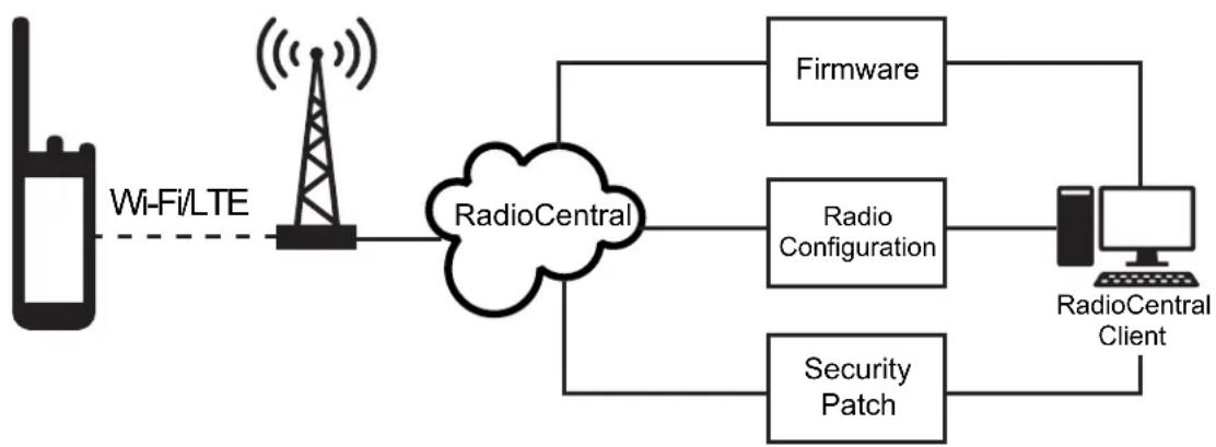
flowchart
graph LR
    A["Wi-Fi/LTE"] --> B["RadioCentral"]
    B --> C["Firmware"]
    B --> D["Radio Configuration"]
    B --> E["Security Patch"]
    C --> F["RadioCentral Client"]
    D --> F
    E --> F
Seamless updates of firmware (full and differential), radio configuration, and security updates are scheduled by the radio system administrator. As a user, you are given a choice to install immediately or delay for later.
With Seamless Over-The-Air-Programming, you can apply a software feature to your radios on the go. After the new software features license is loaded into RadioCentral, a provisioning job can be scheduled to enable the feature through Wi-Fi/LTE. Your radio service provider can also schedule a software update for your radio.
When an update is available, your radio automatically downloads the update package. After the package is downloaded, you can choose to install immediately or later.
You or your service provider can reset your radio to factory settings by using this feature.
Chapter 19
Voice Operating Transmission
Voice Operating Transmission (VOX) allows you to initiate hands-free voice-activated calls on a programmed channel. When your VOX-capable accessory detects voice, your radio automatically transmits for a programmed period.
Google Assistant and Voice Control are mutually exclusive with VOX.

NOTE:
VOX is unable to initiate hands-free voice-activated calls if your radio is connected to any Bluetooth accessories.
This feature is not applicable in Citizen Band channels that are in the same frequency.
Contact your dealer or administrator for more information.
19.1
Setting Voice Operating Transmission
Procedure:
Perform one of the following actions:

- From the Radio Control Widget, tap Radio Quick Settings → VOX.
- From the Menu Feature Launcher Widget, tap More → VOX.
Chapter 20
Text to Speech
This feature enables the radio to audibly indicate the following features:
- Current Channel
- Current Zone
- Programmed button feature on or off
- Content of received text messages
- Capacity Max Status

NOTE:
• Supports multiple languages.
- Must be preconfigured in the RadioCentral (RC) software.
20.1
Selecting Text to Speech Preferred Engine
Procedure:
From Settings, tap Accessibility → Text-to-speech output → Preferred Engine →

NOTE: Motorola Solutions recommends you to select Voice Control Response as the Text to Speech preferred engine for your radio.
20.2
Checking the Text to Speech Configured Language
Procedure:
-
From Settings, tap Accessibility → Text-to-speech output → Preferred Engine.
-
Tap the gear icon next to the Preferred Engine.

NOTE: If you change your radio display language, then you must configure the text to speech language through RadioCentral (RC) software to match the language. You can see the notification of the new downloaded language from the notification panel when you change the language.
Chapter 21
Text Messaging
This feature allows you to quickly send and receive messages directly from your radio.
The maximum length of a text message is 200 characters. Local date and time are time stamped on the messages. Your messages are organized into threads based on the messages subject line (if available) and the senders ID.
21.1
Accessing Text Messages
Procedure:
Perform one of the following actions:
| Option Actions | |
| Viewing text message | From the menu, tap ^ lessenger →. lessenger →. |
| Searching for text message | Tap Search →. |
| Sending text mes-sage through M-Con-tacts | a. From the menu, tap ^ M-Contacts →Message.b. Compose the message, and tap M-Contacts →Message.b. Compose the message, and tap  . . |
| Sending text mes-sage through dialer | a. From the menu, tap ^ contacts →Float Action Button →Dialer.b. Enter, and tap More →Message →to Message.c. Compose the message, and tap contacts →Float Action Button →Dialer.b. Enter, and tap More →Message →to Message.c. Compose the message, and tap  . . |
| Creating a new mes-sage | a. From the menu, tap ^ M-Messenger → M-Messenger →  Add or Add or  New Conversation.b. Select. c. Compose the message, and tap send. New Conversation.b. Select. c. Compose the message, and tap send. |
| Responding to text message with Quick Text | a. From the menu, tap  M-Contacts →Message.b. Press the programmed One Touch Message button. M-Contacts →Message.b. Press the programmed One Touch Message button. |
| Forwarding a mes-sage | a. From the menu, tap  M-Messenger →.b. Tap and hold the selected message, tap Forward →→Send. M-Messenger →.b. Tap and hold the selected message, tap Forward →→Send. |
| Copying a message | a. From the menu, tap  M-Messenger →.b. Tap and hold the selected message, tap Copy.c. Tap and hold the input field, tap Paste. M-Messenger →.b. Tap and hold the selected message, tap Copy.c. Tap and hold the input field, tap Paste. |
| Deleting a single message | a. From the menu, tap  M-Messenger →.b. Tap and hold the selected message, and tap Delete → Delete. M-Messenger →.b. Tap and hold the selected message, and tap Delete → Delete. |
21.2
Setting Message Alert Tone
Procedure:
- From the menu, tap

- Tap
→

More → Edit Contact → Message Alert.
-
Select the preferred message alert:
-
Repetitive
-
Momentary
-
Tap Save.

Chapter 22
Security
This feature allows the administrator or other radio subscriber to put a radio into a non-functional state when the radio is missing or in an unknown hand. The radio stays in this state regardless of its power changes.
The radio can only be uninhibited by receiving an uninhibited command from the administrator or other radio subscriber.
22.1
Disabling Radio
Procedure:
Perform one of the following actions:
| Option Actions | |
| Disabling radio through M-Contacts | a. From the menu, tap  _contacts.b. Tap → More → R. Disable. _contacts.b. Tap → More → R. Disable. |
| Disabling radio with Authentication through M-Contacts | a. From the menu, tap  _contacts.b. Tap → More → R. Disable →→Save.NOTE: Applicable to Conventional Digital only. _contacts.b. Tap → More → R. Disable →→Save.NOTE: Applicable to Conventional Digital only. |
| Disabling radio through programmable feature button | a. Press the programmed Radio Enable/Disable button.b. Tap → down → Disable. |
22.2
Enabling Radio
Procedure:
Perform one of the following actions:
| Option Actions | |
| Enabling radio through M-Contacts | a. From the menu, tap [SYKB] contacts.b. Tap → More → R. Enable. |
| Enabling radio with Authentication through M-Contacts | a. From the menu, tap  contacts.b. Tap → More → R. Enable →NOTE: Applicable to Conventional Digital only. contacts.b. Tap → More → R. Enable →NOTE: Applicable to Conventional Digital only. |
| Enabling radio through programmable feature button | a. Press the programmed Radio Enable button.b. Tap → down → Enable. |
Chapter 23
Call Indicator Settings
This feature allows you to configure call or text message tones.
23.1
Assigning Ring Styles
Procedure:
- From the home screen, tap More → More → M-Contacts →
→ More → Edit Contact. - Perform one of the following actions:
- To assign ringtone, tap Ringtone →
- To assign message alert, tap Message Alert →
Chapter 24
Recent Calls
You can view missed, answered, outgoing private calls, call alerts, and emergency alerts in Recent Calls.
In the list of recent calls, it is arranged in an ascending order of time with the most recent first. The list can store up to 50 recent calls and the oldest ones are deleted automatically.
For recent calls that you have not visited, it will appear in a bold font. You can choose to initiate a call straight away from the recent calls screen.
The following shows the details from the Recent Calls screen:
Figure 3: Recent Calls Screen
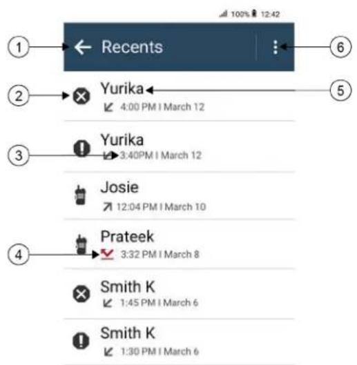
flowchart
graph TD
    A["1"] --> B["Recents"]
    B --> C["2"]
    C --> D["Yurika"]
    D --> E["3"]
    E --> F["Yurika"]
    F --> G["4"]
    G --> H["5"]
    H --> I["6"]
    D --> J["Yurika 4:00 PM / March 12"]
    F --> K["Yurika 3:40PM / March 12"]
    G --> L["Josie 12:04 PM / March 10"]
    H --> M["Prateek 3:32 PM / March 8"]
    I --> N["Smith K 1:45 PM / March 6"]
    J --> O["Smith K 1:30 PM / March 6"]
No. Description
| 1 Back to previous screen |
| 2 Call Type |
| 3 Timestamps |
| 4 Call type activity status |
| 5 Dialed Number |
| 6 Delete options |
24.1
LMR Contacts Icons
Table 21: Call Type Icons
| Icon Name | |
 | Emergency Call |
 | Call |
 | Call Alert |
 | Emergency Cancel |
 | Status |
Table 22: Activity Status Icons
| Icon Name | |
 | Missed Call |
 | Received Call |
 | Transmitted Call |
24.2
Accessing Recent Calls
Procedure:
- From the home screen, tap More → Recent Calls.
- Perform one of the following actions:
- To view recent calls, scroll through the list.
• To delete a selected contact, tap • More → Select to Delete →

• To delete all contacts, tap • More → Delete All → Delete.
- To add new contacts, tap
→ ∴ More → Add to Contact → → Save. - To edit existing contact, tap
→ More → → Save. - To call the contact, tap
→ PTT.

NOTE: You can only add, edit, or delete WAVE contacts through WAVEOnCloud portal.
Chapter 25
Call Queue
When there are no resources available to process a call, Call Queue enables the call request to be placed in the system queue for the next available resources.
25.1
Receiving a Call Queue
Procedure:
Press and hold the PTT button.
Result:
A tone is heard and the top display shows Call in Queue.
If receiving a Call Setup is successful, your radio shows the following indications:
- A positive indicator tone sounds.
- The green LED blinks.
- The display shows the call type icon, ID or alias.
- You have up to 4 seconds to press and hold the PTT button to begin voice transmission.
If receiving a Call Queue is unsuccessful, your radio shows the following indications: - A negative indicator tone sounds.
- The display shows the failure notice screen.
- Radio terminates the call and exit the call setup.
Chapter 26
Priority Call
Priority Call allows the system to preempt one of the ongoing non-priority calls and initiate the requested high priority call when all channels are busy.
With all channels occupied with high priority calls, the system does not preempt any calls, and places the requesting high-priority call into call queue. If the system fails to place the requesting high-priority call into call queue, it declares failure.
The default settings for Priority Call are preconfigured. When the following features are used, the call priority level reverts automatically to the preconfigured setting.
- All voice calls
- DMR III Text Message/Text Message
26.1
Switching the Priority Call Level
Procedure:
Press the programmed Toggle Call Priority Level button.
Result:
If High Priority is enabled, your radio shows the following indications:
- The display shows Next Call: High Priority.
- The Call Priority High icon appears on the home screen.
If Normal Priority is enabled, your radio shows the following indications: - The display shows Next Call: Normal Priority.
- The Call Priority High icon disappears on the home screen.
Chapter 27
Scan
Depending on the supported system available on your radio, your radio may have different behavior on Scan.
Channel Scan
Channel Scan is available for Other Systems.
When you start a scan, your radio scans through the programmed scan list for the current channel looking for voice activity. If you are on a digital channel, and your radio locks onto an analog channel, your radio automatically switches from digital mode to analog mode during the call and the same behavior occurs if you are on analog channel.
Table 23: Scan Methods
| Method Description |
| Main Channel Scan (Manual) Your radio scans all the channels or groups in your scan list. When scanning, your radio may, depending on the settings, automatically start on the last scanned active channel or group, or on the channel where scan was initiated. |
| Auto Scan (Automatic) Your radio automatically starts scanning when you select a channel or group that has Auto Scan enabled. |
When you miss a call from a talkgroup or a channel that is in your scan list, you might be having the following situations:
- Scan feature is not on.
- Scan list member has been disabled through the menu.
- You are already participating in another call.
- For Multi-site system, no member of the scanned group is registered at your current site.

NOTE: If your radio joins a call for a Zone Scan List member from a different Zone and Call Hang Timer expires before you are able to respond, you must navigate to the Zone and Channel of the Scan List Member and start a new call to respond.
27.1
Turning Scan On or Off
Procedure:
Perform one of the following actions:

- From the Radio Control Widget, tap Radio Quick Settings → Scan.
- From the Menu Feature Launcher Widget, tap More → Scan.
- Press the programmed Scan button.
27.2
Scan Talkback
The Talkback feature allows you to respond to a transmission while scanning.
Depending on how you configure the Scan Talkback feature, you will see two different scenarios if you press the PTT button when your radio scans into a call from the selectable group scan list.
Table 24: Scan Talkback Type
| Type Description |
| Scan Talkback Disabled During an ongoing scanned call, if the PTT button is pressed, the scanned call is terminated and a new call is launched. |
| Scan Talkback Enabled During an ongoing scanned call, if the PTT button is pressed, you can talkback to the scanned call. |

NOTE:
If you face the following scenarios:
- Scan into a call for a group that is not assigned to a channel position in the currently selected zone.
- Miss the Hang Time of the call.
Perform the following actions:
- Switch to the proper zone.
- Select the channel position of the group to talk back to that group.
27.3
Nuisance Channels
Nuisance Channel is a channel that generates unwanted call continually.
You can temporarily remove the unwanted channel from the scan list and restore it back later on. This capability does not apply to the channel designated as the Selected Channel.
27.3.1
Deleting Nuisance Channels
Prerequisites: Your radio is scanned into the Nuisance Channel.
Procedure:
- Press the programmed Nuisance Delete button until you hear a tone.
- Release the programmed Nuisance Delete button.
27.3.2
Restoring Nuisance Channels
Procedure:
Perform one of the following actions:
- Restart your radio.
- Turn off and then turn on the scan.
- Change the channel.
- Change the zone.
27.4
Priority Monitor
Priority Monitor allows your radio to receive transmission from talkgroups with higher priority during talkgroup call. This feature is only applicable to members in Receive Group List.

NOTE: This feature can only be accessed when Talkgroup Scan feature is enabled.
Priority talkgroups are Priority 1 (P1) and Priority 2 (P2). Your radio receives transmission according to the following priority:
- Emergency Call for P1 Talkgroup.
- Emergency Call for P2 Talkgroup.
- Emergency Call for non-priority Talkgroup in the Receive Group List.
- All Call.
- P1 Talkgroup Call.
- P2 Talkgroup Call.
- Non-priority Talkgroup in the Receive Group List.
27.5
Receive Group List
Receive Group List allows you to create and assign members on the talkgroup scan list. You can have a maximum of 16 members in a list.

NOTE: To add member into the list, the talkgroup must first be configured in the radio.
For Capacity Max, when your radio is programmed to edit the scan list, you can perform the following actions:
- Add, remove, and edit priority for talkgroups.
- Add, remove, and edit affiliation talkgroups.
For Other Systems, when your radio is programmed to edit the scan list, you can perform the following actions: - Add or remove talkgroups.
- Add, remove, and edit priority for talkgroups.
- Add, remove, and edit affiliation talkgroups.
- Replace the existing scan list with a new scan list.
If a talkgroup is programmed as Permanent Talkgroup, you are unable to edit the talkgroup from the scan list.
27.6
Scan Lists
You can create and assign individual channels or groups in Scan Lists. Your radio scans for voice activity by cycling through the channel or group sequence specified in the scan list for the current channel or group. Scan List also known as Receive Group List.
Your radio can support up to 250 scan lists, with a maximum of 16 members in a list. Each scan list supports a mixture of analog and digital entries.
The Priority icon on the left of member ID indicates whether the member is on Priority 1 or Priority 2 channel list. You cannot have multiple Priority 1 and Priority 2 channels in a scan list. There is no icon if the priority is set to None.

NOTE: This feature is not applicable to Capacity Plus.
27.6.1
Accessing Scan List
Procedure:
- From the Menu Feature Launcher Widget, tap Scan List or More → Scan List.

NOTE: If the Scan List icon is grey out on the Menu Feature Launcher, you are unable to access the scan list.
- Perform one of the following actions:
| Option Actions | |
| Setting Active Scan List | a. Perform one of the following actions:When there is no active scan list, tapView/Edit Scan List→.To change to a new active scan list, tap→Set Active Scan List →. |
| Viewing Scan List Scroll through the list of members. | |
| Adding priorities | a. Select the required tab according to your systems.For Capacity Max, you can select the scan list members from Scan List or Talkgroup tab.For Other Systems, you can select the scan list members from Scan List or Channel tab.b. Tap→.NOTE: If Priority 1 is not set, Priority 2 is grey out. |
| Deleting Scan List member | Tap→. |
| Searching Scan List | Tap Search →. |

NOTE: When the scan list is full, you are unable to add members into the list as it appears grey out. If the Scan List is empty, the Radio Control Widget shows Empty Scan List.
27.7
Flexible Receive List
The Flexible Receive List feature allows you to create and assign members on the receive talkgroup list.
Your radio can support a maximum of 16 members in the list.

NOTE: This feature is only applicable to Capacity Plus.
27.7.1
Accessing Flexible Receive List
Procedure:
- From the Menu Feature Launcher Widget, tap Scan List or More → Scan List.
- On the Talkgroup tab, select the required member and perform one of the following actions:
- To add member, tap + Add → Add to List - To remove member, tap Scan List → Remove from List
27.8
Multi-Talkgroup Affiliation
Your radio can be configured for up to seven talkgroups at a site.
Up to seven talkgroups can be assigned as affiliation talkgroups from the 16 talkgroups in the Receive Group List. The selected talkgroup and the priority talkgroups are automatically affiliated.
27.8.1
Adding Talkgroup Affiliation
Procedure:
From the Menu Feature Launcher Widget, tap Scan List or More → Talkgroup →
27.8.2
Removing Talkgroup Affiliation
Procedure:
From the Menu Feature Launcher Widget, tap Scan List or More → Talkgroup →
Chapter 28
Location
The Global Navigation Satellite System (GNSS) integrates information from the Global Positioning System (GPS), Global Navigation Satellite System (GLONASS), BeiDou Navigation Satellite System, and Galileo to determine the approximate geographical location of your radio.
28.1
Turning Location On or Off
Turning Location On
Procedure:
Perform one of the following actions:
- Swipe down the notification panel, tap Location.
- From Settings, tap Location → Use Location → On.
Turning Location Off
Procedure:
Perform one of the following actions:
- Swipe down the notification panel, tap Location.
- From Settings, tap Location → Use Location → Off.
28.2
Indoor Location
You can use Indoor Location to keep track of the location of radio users. When Indoor Location is activated, the radio is in a limited discoverable mode. Dedicated beacons are used to locate the radio and determine the position.
28.2.1
Turning Indoor Location On or Off
Prerequisites: Ensure to enable Indoor Location in RadioCentral.
Turning Indoor Location On
Prerequisites: Make sure that Bluetooth is turned on in your radio.
Procedure:
From Settings, tap Location → Beacon Indoor Location → On.
Result: A message of Beacon Indoor Location enabled appears in the notification panel.
Turning Indoor Location Off
Procedure:
Perform one of the following actions:
- Swipe down the notification panel, tap Bluetooth to turn off.
- Swipe down the notification panel, tap Beacon Indoor Location enabled message → Beacon Indoor Location → Off.
- From Settings, tap Location → Beacon Indoor Location → Off.
Chapter 29
Conventional Squelch Operation
This feature filters out unwanted calls with low signal strength or channels that have a higher than normal background noise.
Analog Options
Tone Private Line, Digital Private-Line, and carrier squelch is available (preprogrammed) per channel.
Option Result
Carrier squelch You hear all traffic on a channel.
Tone Private Line or Digital Private-Line The radio responds only to your messages.
Digital Options
One or more of the following options may be preprogrammed in your radio. Contact your dealer or administrator for more information.
Option Result
Digital Carrier-Operated Squelch You hear all digital traffic.
Normal Squelch You hear any digital traffic having the correct net-work access code.
Selective Switch You hear any digital traffic having the correct net-work access code and correct talkgroup.
Chapter 30
Using the PL Defeat Feature
This feature allows you to override any coded squelch that preprogrammed to a channel. The radio also unmutes to any digital activity on a digital channel. When this feature is active, the Carrier Squelch status indicator is displayed.
Procedure:
Place the preprogrammed PL Defeat switch in the PL Defeat position.
One of the following occurs:
- The radio plays the active transmission on the channel.
- If no activity is present, the radio is muted
Chapter 31
Monitor Feature
The feature allows you to remotely activate the microphone of a target radio. You can use this feature to monitor any audible activity surrounding the target radio.
31.1
Monitoring Channels
Procedure:
- Press and hold the programmed Monitor button.
Your radio shows the following indications:
- You hear the radio activity.
- The yellow LED illuminates.
-
The display shows the Monitor icon.
-
To call, press and hold the PTT button.
-
To listen, release the PTT button.
31.2
Permanent Monitor
The Permanent Monitor feature is used to continuously monitor a selected channel for activity.
31.2.1
Setting the Permanent Monitor
Procedure:
Press and hold the programmed Permanent Monitor button.
Result:
When your radio enters the mode, your radio shows the following indications:
- An alert tone sounds.
- The display shows PERM MON ON and the Monitor icon.
When your radio exits the mode, your radio shows the following indications: - An alert tone sounds.
- The display shows PERM MON OFF.
Chapter 32
Trunking System Control
This feature allows your radio to communicate the trunking status when on a trunking channel. Your radio can communicate different types of trunking statuses.
Table 25: Types of Trunking System Status
| Types Description | |
| Out of Range | When your radio goes out of the range, it can no longer lock onto a control channel.You hear a low-pitched tone, and or the display shows the currently selected zone or channel combination, and Out of range notification. Your radio remains in this out-of-range condition until it locks onto a control channel, or if it is turned off. |
| Site Trunking^5 | If the Trunk Controller loses communication with any site, that site reverts to site trunking. When this occurs, you can communicate only with the radios within your trunking site. |
| Affiliation Failed | Affiliation failed is when the radio is successfully locked and registered to a site, but fails to affiliate to Unified Knob Position (UKP).Your radio displays failed message, the site alias, and the UKP alias. |
| Registration Denied | Registration denied is when your radio registration is denied on a site.Your radio displays failed message and the UKP alias. |
32.1
Viewing RSSI Value
Procedure:
Press the 2-Dot Programmable Feature button five times.
Result: The top display shows the RSSI value.
Chapter 33
Dynamic Group Number Assignment
Dynamic Group Number Assignment (DGNA) is a feature that allows the third-party console to assign and remove talkgroup dynamically to a radio from over the air.
When the console assigns DGNA to your radio, your current channel is in DGNA mode and shows the followings:
- A tone sounds.
- The top display momentarily shows DGNA ASSGNED.
- The display momentarily shows
is assigned. - The DGNA icon appears in the top display and Radio Control Widget.
- The top display and Radio Control Widget show DGNA talkgroup alias.
When the console removes DGNA from your radio, your radio restores the previous talkgroup and shows the followings:
- A tone sounds.
- The top display momentarily shows DGNA REMOVED.
- The display momentarily shows
is removed. - The DGNA icon disappears from the top display and Radio Control Widget.
- The top display and radio control widget show the previous talkgroup alias.
Depending on how your radio is programmed, you can view, edit, and listen to the original scan lists channels and the non-DGNA talkgroups.
When your radio is in DGNA mode, press and hold the PTT button action allows you to communicate only with the current DGNA talkgroup. To communicate with the previous non-DGNA talkgroup, program the programmed One Touch Access button.

NOTE: Check with your dealer or system administrator to determine how your radio has been programmed.
33.1
Making DGNA Calls
Prerequisites: Ensure your current channel is in DGNA mode.
Procedure:
To call, press and hold the PTT button.
Result: Your radio shows the following indications:
• A DGNA tone sounds.
- The DGNA icon appears in the top display and Radio Control Widget.
- The top display and Radio Control Widget show DGNA talkgroup alias.
33.2
Making Non-DGNA Calls
Procedure:
Perform one of the following actions:
- If your radio is in DGNA mode, press the programmed One Touch Access button.

NOTE:
If your radio is not in DGNA mode and you press the One Touch Access button, your radio sounds a negative tone, indicating error. The display remains unchanged.
- If your radio is not in DGNA mode, press and hold the PTT button.

NOTE:
When a PTT button is press before a negative tone sounds, your radio returns to the home screen. When your radio is in the home screen, a PTT press makes a call to the DGNA talkgroup.
Result:
Your radio shows the following indications:
- A positive tone sounds.
• Voice Announcement sounds. - The top display and Radio Control Widget shows
and Press PTT momentarily.
33.3
Receiving and Responding to DGNA Calls
When you receive a DGNA call, your radio shows the following indications:
• A DGNA tone sounds.
- The DGNA icon appears in the top display and Radio Control Widget.
- Your radio unmutes and the incoming call sounds through the speaker.
Procedure:
- To call, press and hold the PTT button.
- To listen, release the PTT button.
Chapter 34
Auto Roaming
Depending on your radio system, this feature allows your radio to roam to a required site.
A multi-site channel has auto roaming capability when it is attached with a site search list.
Your radio can roam to different sites through site search.
Table 26: Types of Site Search
| Types Description | |
| Passive Site Search (PassiveSS) | When Site Lock is turned off, PassiveSS scans available sites and selects the strongest signal as current home. |
| Active Site Search (ActiveSS) ActiveSS sends wakeup requests to the repeater. | |
34.1
Turning Site Lock On or Off
Turning Site Lock On
Procedure:
- From the Menu Feature Launcher Widget, tap
- Toggle Site Lock to on.

Result: Your radio locks the current site and stops auto roaming. The Roam icon disappears.
Turning Site Lock Off
Procedure:
- From the Menu Feature Launcher Widget, tap
More →

Roam.
- Toggle Site Lock to on.
Result: Your radio enables auto roaming. The Roam icon appears.
34.2
Accessing Active Site Search
Procedure:
From the Menu Feature Launcher Widget, tap

More →

Roam → Active Search.
Your radio searches for a site.
Result:
- If a site is found, your radio displays a message with the site alias and updates the site alias onto Radio Control Widget.
- If a site is not found, your radio displays a temporary error message.
34.3
Accessing Current Site Information
When and where to use: This feature is only available for Capacity Plus and Capacity Max systems.
Procedure:
From the Menu Feature Launcher Widget, tap

More →

Roam → Current Site Lock.
34.4
Accessing Neighboring Site Information
When and where to use: This feature is only available for Capacity Max system.
Procedure:
From the Menu Feature Launcher Widget, tap

More →

Roam → Neighboring Site Info.
Chapter 35
Radio Check
If enabled, this feature allows you to determine if another radio is active in a system without disturbing the user of that radio. No audible or visual notification is shown on the target radio.
This feature is only applicable for subscriber IDs.
35.1
Sending Radio Check
Procedure:
- From the menu, tap

M-Contacts.
- Perform one of the following actions:
| Option Actions | |
| Sending radio check through saved contacts | a. Navigate to the.b. Tap and hold theQuick Actionicon.c. Tap More → R. Check. |
| Sending radio check through dialer | a. Tap Floating Action Button → Dia-ler.b. Enter the.c. Tap More → Radio Check. |
Chapter 36
Transmit Interrupt (Supervisory Override)
Transmit Interrupt features allows your radio to interrupt an in progress clear or a privacy voice transmission.
For LMR and Converge Capacity Max, you are able to transmit and receive interrupts. For Converged WAVE and WAVE only channel, transmit interrupt is known as Supervisory Override and you are only able to receive interrupts.
Only talkgroup members with supervisor role are able to interrupt on going calls.
36.1
Initiating Transmit Interrupt
Procedure:
To interrupt an ongoing call, perform one of the following actions:
- Press the PTT button.
- Press the Emergency button.
- For non Capacity Max, perform data transmission.
- For non Capacity Max, press the programmed TX Interrupt Remote Dekey button.
Result:
For Converged WAVE and WAVE only channel, the receiving radio display shows the following indication:

• Supervisory override icon
- Call alias
If there is no call alias information, you radio display shows Listening....
Chapter 37
Auto-Range Transponder System
The Auto-Range Transponder System (ARTS) is an analog-only feature designed to inform you when your radio is out-of-range of other ARTS-equipped radios.
ARTS-equipped radios transmit or receive signals periodically to confirm that they are within range of each other.
Your radio provides indications as follows:
Table 27: Auto-Range Transponder System Indications
| Indication Description | |
| First-Time Alert | A tone sounds. |
| ARTS-in-Range Alert | A tone sounds, if programmed. |
| ARTS-Out-of-Range Alert | A tone sounds.The red LED rapidly blinks.The front display shows ARTS Out of Range.The top displays show ARTS OUT RNGE. |
Chapter 38
Applications
This section contains information on applications available on your radio. You can access these applications through the Home Screen or swiping up from the bottom of the Home Screen to open Applications Menu window.

NOTE: Do not use PMKN4230_ and PMKN4265_ for data transfer or programming in a hazardous environment.
Table 28: Applications
| Icon Name Description | |
| Calculator Allows you to perform basic and scientific arithmetic functions. | |
| Calendar Allows you to manage events and appointments. | |
| Camera Allows you to take photos and videos. | |
| Google Chrome Fast, easy, and secure browsing with Google Chrome. | |
| Clock Allows you to set an alarm, stopwatch, or timer. | |
| Contacts Allows you to manage contact information. | |
| Google Drive All files within reach from any smartphone, tablet, or computer. Anytime. | |
| Google Duo Be together in the moment.Never miss a moment. | |
| Files Allows you to view and manage files. | |
| Gallery Allows you to view photos or videos. | |
| Gmail Email by Google: secure, smart, and easy to use. | |
| Google Stay in the know with the Google app. | |
| Keep Notes Allows you to create, store, and categorize notes, lists, reminders, images, audio, and many more. | |
| Google Maps Explore and navigate your world with Google Maps. Find places you'll love, connect with businesses you're interested in, and get around with real-time traffic information. | |
| Messages Allows you to send and receive messages. | |
| Google Photos The home for all your memories. | |
| Icon Name Description | ||
 | Google Play Movies and TV | The newest releases plus all your favourites, on any screen. |
 | Google Play Google Play is your entertainment unbound. | |
 | Settings Provides settings to configure the device. | |
 | Sound Recorder Allows you to record sounds. | |
 | WAVE Provides secure Push-to-Talk (PTT) service on the go. | |
 | YouTube See what the world is watching on YouTube. | |
 | YouTube Music Discover all the music on YouTube that you cannot find anywhere else, organized in one new app and web. | |
38.1
Camera
You can use the Camera application to take photos or record videos.
38.1.1
Taking Photos
Procedure:
- From the menu, tap Camera.
- Perform one of the following actions:
- To take photo using rear camera, tap

- To take photo using front camera, tap


- To zoom in or out, press two fingers on the display and pinch or expand fingers.
The zoom controls appear on the screen.
38.1.2
Recording Videos

NOTE: You are unable to transmit LTE call during video recording.
Procedure:
- From the menu, tap Camera → Video Your video has start recording.
- To pause the video, tap ☐ause.
-
Tap stop the recording, tap Stop Record.
-
To zoom in or out, press two fingers on the display and pinch or expand fingers.
The zoom controls appear on the screen.
38.2
Gallery
You can manage your albums, photos, or videos using the Gallery application.

NOTE: The device supports the following image formats: JPEG, GIF, PNG, HEICand BMP.
You can use Photos to perform the following actions:
• View albums, photos, and videos
- Play videos
- Perform basic editing on albums, photos, and videos
- Set photos as a wallpaper
- Set photos as a contact photo
- Share photos and videos
The Gallery application contains all albums, photos, and videos stored on the microSD card and in the internal memory.
38.2.1
Viewing Gallery
Procedure:
- From the menu, tap Gallery.
- Perform one of the following actions:
- Tap an album of your choice.
- Tap a photo.
- To view the next or previous photo in the album, swipe left or right.
- To view controls, tap a photo.
- To zoom in or zoom out, double tap or press two fingers on the display and pinch or expand fingers on a photo.
- To view parts that are not in view, drag the photo.
38.2.2
Sharing Items from Photos
Procedure:
-
From the menu, tap Gallery.
-
To share items, tap
→ Share → .
38.2.3
Deleting Items from Gallery
Procedure:
-
From the menu, tap Gallery.
-
To delete items, tap
→ Delete → OK.
38.2.4
Cropping Photos
Procedure:
-
From the menu, tap Gallery.
-
To crop photos, tap
→ Edit → Crop.
The cropping grid appears.
- Perform one of the following actions:
| Option Actions | |
| Cropping the photo manually | a. To select the portion of the photo to crop, adjust the endpoints. |
| Choosing automatic cropping dimensions | a. Tap 1:1.b. If you want to view the original photo, tap Original. |
-
To confirm, tap √s.
-
To save, tap SAVE.
38.2.5
Rotating Photos
Procedure:
-
From the menu, tap Gallery.
-
To rotate photos, tap
→ Edit → Crop → Rotate
The photo rotates to 90^ clockwise. Each tap rotates the photo to another 90^ .
- Tap SAVE to confirm.
38.2.6
Watching Videos
Procedure:
- From the menu, tap Gallery.
- To watch videos, tap Videos →
→ Play → . - To see the video playback or continue where you left off last time, drag the video progress bar.
- To return to the previous screen, tap
38.3
Adding Contacts on Android
Procedure:
- Tap

Contacts →
Add.

- Fill in the related information and tap Save.
38.4
Cellular Calls
The radio model supported for this feature is MSLB-MKZ900ti and MSLB-MKZ920ti.

NOTE: Support for video over LTE is dependent on your SIM carrier's availability.
Ensure you have a voice capability SIM card. You have the option of choosing a PSIM (physical SIM) or eSIM (nonphysical SIM). By default, your radio selects the PSIM when both SIM cards are available, unless the PSIM system is facing difficulties.
During calls, you will only be able to receive calls to your default SIM. Calls received on the other SIM will be forwarded to voicemail.
You cannot toggle the speaker option on the call screen. Attach an accessory to switch the audio route to your accessory. Making and answering cellular call by holding the radio up to your ear is not supported. The default audio feature is through the speaker mode.

NOTE: This feature is not applicable to North America.
38.4.1
Making Cellular Calls
You can choose a preferred default SIM for Calls, SMS, and Mobile data from the radio Settings.
Prerequisites:
To select the default SIM, tap Setting → Network & Internet → Required SIM → Calls Preference, then pick the preferred SIM or tap Ask every time.
Procedure:
- From the home screen, swipe up.
- From the menu, tap Settings.
- To make cellular calls, perform one of the following actions:
| Option Actions | |
| Making 3G Call | a. Tap Network & Internet → Mobile Network → Preferred Network Type → WCDMAb. From the menu, tap Phone.c. Enter theat the dialpad and tap Call. |
| Making LTE Voice Call | a. Tap Network & Internet → Mobile Network → IMS.NOTE: Depending on your region, IMS option may be displayed as VoLTE or 4G Calling.b. Tap Network & Internet → Mobile Network → Preferred Network Type.c. From Preferred Network Type, choose and tap one of the following:i. LTEii. LTE/WCDMAd. From the menu, tap Phone.e. Enter theat the dialpad and tap Call. |
| Making LTE Video Call | a. Tap Network & Internet → Mobile Network → IMS.NOTE: Depending on your region, IMS option may be displayed as VoLTE or 4G Calling.b. Tap Network & Internet → Mobile Network → Preferred Network Type.c. From Preferred Network Type, choose and tap one of the following:i. LTEii. LTE/WCDMAd. Tap Network & Internet → Mobile Network → Advanced → Operator video calling.e. From the menu, tap Phone.f. Enter theat the dialpad and tap the video call icon.g. Tap Flip camera after the call is answered.NOTE:To ensure LTE video call is using the cam-era, flip the camera on both the caller and the receiver side.The quality of the video call depends on the signal strength and the availability of IP Multimedia Subsystem (IMS). |
38.5
Scanning Barcode or QR Code
You can perform Barcode and QR Code scanning on your respective application that stores the decoded barcode (barcode database application) with Scandit™ Keyboard Wedge application.
Prerequisites: Perform the following on first time activation:
- Request for Activation QR Code from dealer or Scandit.
- Inform dealer to assigned Keyboard Wedge - Barcode Scan to one of the programmable button.
- Download Scandit Keyboard Wedge from Google Play.
- Activate the app with Activation QR Code.
- Select Scandit Keyboard Wedge as your keyboard.
Procedure:
- Launch your barcode database application.
- To change your current keyboard, tap ☐ Keyboard → Scandit Keyboard Wedge.
-
Press the programmed Keyboard Wedge - Barcode Scan button.
-
Aim your camera to the barcode or QR code.

NOTE: Make sure the barcode or QR code is captured in the rectangular box.
Result: The barcode or QR code is captured and decoded. The decoded output is shown in the text field.
38.6
Turning On the Flash Light
Procedure:
Swipe down the notification panel, tap 📋 Flashlight.
38.7
Exploring Files
Procedure:
- From the menu, tap

- Select the
. - Perform one of the following actions:
| Option Actions | |
| Viewing the file Tap on the. | |
| Sharing the file | a. Tap and hold the. b. To share the downloaded item, tap Share → Share via →. |
| Searching for a file | a. Tap Search. b. Type in your. |
| Deleting a file | a. Tap and hold the. b. To delete, tap  Delete → Move 1 file to Trash. Delete → Move 1 file to Trash. |
| For more options Tap | More. |
Chapter 39
Broadband PTT Application

NOTE:
Broadband PTT Application is not the official application name and is different depending on your region.
Verify the WAVE icon when you download the application from Google Play Store. Contact your dealer or administrator for more information.
The application provides instant communications at the push of a button.
When you are in Broadband PTT mode, the LMR operation is disabled. The Emergency button, PTT button, Volume knob, and Channel Selector knob are now functioning according to the Broadband PTT configuration.
All the features described in the sections are supported by the following requirements:
- Application version 10.0.1.51, 11.2.0.13, or above
- Latest software version as stated in Software Version on page 18.
For more information, see https://waveoncloud.com/Home/Help.
39.1
Checking Broadband PTT Application Version
Procedure:
From the Broadband PTT application, navigate to About.
39.2
Turning Broadband PTT Mode On or Off
Prerequisites: Download the Broadband PTT application from Google Play Store.
Procedure:
From the Radio Control Widget, tap

Radio Quick Settings → Broadband PTT.
Result:
If Broadband PTT mode is turned on, your radio shows the following indications:
- The display shows Broadband PTT banner.
- A pop-up message appears LMR Mode Disabled. Please sign into the Broadband PTT app.

NOTE: If you try to launch LMR features while Broadband PTT mode is on, your radio displays Features not allowed.
If Broadband PTT mode is turned off, your radio shows the following indications: receives following reminders:
- The Broadband PTT banner disappears.
- A pop-up message appears LMR Mode Enabled. Please sign out of the Broadband PTT app.

NOTE:
- Ensure to log out from the Broadband PTT Application to avoid any issue when working in the LMR mode.
- If you do not want to receive the reminder when turning Broadband PTT mode on or off, select DON'T REMIND. You will receive the reminder again if you power cycle your radio.
- After cycle power your radio, you are required to enter Broadband PTT mode manually.
39.3
Logging in Broadband PTT Application
Procedure:
- Tap on the

- Tap Yes to Login.
Result:

NOTE: If activation code is requested during first time login, contact your dealer or administrator for more information.
39.4
Logging Out from Broadband PTT Application
Procedure:
From the Broadband PTT application, navigate to ≡ Menu → Settings → Logout → Yes.
39.5
Broadband PTT Application Overview
Figure 4: Broadband PTT Application Overview
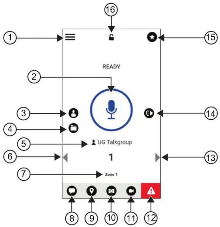
flowchart
graph TD
    A["1"] --> B["≡"]
    B --> C["2"]
    C --> D["3"]
    D --> E["4"]
    E --> F["5"]
    F --> G["6"]
    G --> H["7"]
    H --> I["Zone 1"]
    I --> J["8"]
    I --> K["9"]
    I --> L["10"]
    I --> M["11"]
    I --> N["12"]
    O["16"] --> P["↓"]
    Q["15"] --> R["←"]
    S["14"] --> T["←"]
    U["13"] --> V["←"]
    W["↑"] --> X["UG Talkgroup"]
    X --> Y["1"]
    Z["→"] --> AA["←"]
    AB["→"] --> AC["←"]
Table 29: Broadband PTT Application Overview
Label Name Description
| 1 Menu The Menu Options include the following: |
| Status |
| History |
| Contacts |
| Map |
| Favorites |
| Channels/Zones |
| Talkgroup Scan |
| Tones |
| Use Wi-Fi |
| Ambient Listening (if configured) |
| Settings |
| Tutorial |
| Label Name Description | ||
| About | ||
| 2 PTT Allows you to make calls. | ||
| 3 Contacts Displays your PTT contacts and allows you to search for contacts, start a PTT call, or send an alert. | ||
| 4 Channels and Zones Display available channels and zones, allows you to select the required channel and zone. | ||
| 5 Talkgroup Name Display the current talkgroup name. | ||
| 6 Left Arrow Navigates to the previous talkgroup. | ||
| 7 Zone Display the current zone. | ||
| 8 Message View the current talkgroup conversation. | ||
| 9 Location View your current location. | ||
| 10 Camera Allows you to choose from taking photo or select a file in gallery. | ||
| 11 Video Allows you to stream videos. | ||
| NOTE: This feature is only available if the feature is enabled in the WAVE portal. Contact your dealer or administrator for more information. | ||
| 12 Emergency | Allows you to initiate an emergency. | |
| 13 Right Arrow | Navigates to the next talkgroup. | |
| 14 Speaker On | Allows you to toggle audio route from Bluetooth accessory to radio microphone, speaker, or wired accessory and vice versa. | |
| NOTE: This feature is only available when Blue-tooth accessory is connected to your radio. Use programmable button Audio switch to toggle audio route if there is no Bluetooth accessory connected to your radio. | ||
| 15 Favorites | Displays your favorite PTT contacts and talkgroups.You can quickly start a PTT call to your favorites. | |
| 16 App Lock | When the Broadband PTT app is lock, you cannot use the app until you tap the App Lock to unlock. | |
39.6
Making Talkgroup Calls
Prerequisites: Perform the following actions on the Broadband PTT application settings:
- To enable call when the screen is locked, toggle Call from Lock Screen to on.
- To enable call when the application is running in background, toggle Background Mode to on.
Procedure:
-
To select a channel with an active ID or alias, perform one of the following actions:
-
Toggle the Channel Selector knob.
-
Select the Left or Right arrow on the application.
The display shows Changing talkgroups banner. -
To call, press and hold the PTT or On-Screen PTT button.
- Wait for the Talk Permit Tone to end, and speak into the microphone.
- To listen, release the PTT button.
39.7
Emergency Operation
You can declare an emergency to contact or talkgroup through emergency calling and alert.

NOTE: If your radio does not support Emergency operation, your radio display a notification on the non-activated Emergency feature.
39.7.1
Declaring Emergency
Prerequisites:
- In RadioCentral, set the
as Emergency. - In the Broadband PTT configuration, perform the following actions:
- Allow the emergency initiation.
- Configure the emergency destination.
- Enable special notification with option, For both, if user prefers to receive audio/video notifications based on emergency transmit and receive events.
Procedure:
- Press the Emergency button.
The display shows Emergency Alert pop-up message with 3 seconds countdown.

NOTE: If the Emergency button is pressed during the 3 seconds countdown, the countdown will reset to 3 seconds.
When Emergency is declared successfully, your radio shows the following indications:
• The Emergency tone sounds.
- The display shows Emergency Declared banner.
- To call, press and hold the PTT button.
- To listen, release the PTT button.
39.7.2
Canceling Emergency
Procedure:
- Press the Emergency button.
The display shows Cancel Emergency.
-
Perform one of the following actions:
-
Select Real Emergency Send
- Select False Alarm → Send
Result: When Emergency is canceled successfully, your radio shows the following indications:
• The Emergency tone dissolves.
- The display shows Emergency Canceled banner.
Chapter 40
Authorized Accessories List
Motorola Solutions provides approved accessories to improve the productivity of your radio.
For more information about the accessories, UL accessories, and batteries supported for your radio, see https://learning.motorolasolutions.com/lon with the following Manual Part Numbers:
- MN006920A01, MOTOTRBO ^TM Ion Smart Radio Accessories Leaflet
• MN006806A01, MOTOTRBO Ion UL Manual
Table des matières
VI. DISPOSITIONS RELATIVES AUX BREVETS ET AUX LOGICIELS....16
VII. LOI APPLICABLE....17
8.9 Réglages audio....61
MOTOROLA, MOTO, MOTOROLA SOLUTIONS, and the Stylized M Logo are trademarks or registered trademarks of Motorola Trademark Holdings, LLC and are used under license. Google, Android, Google Play, Youtube, and other marks are trademarks of Google LLC. All other trademarks are the property of their respective owners.
Droits de licence
© 2024 Motorola Solutions, Inc. All Rights Reserved
VI. DISPOSITIONS RELATIVES AUX BREVETS ET AUX LOGICIELS
- https://youtu.be/cYjxoUNCXZo
- https://www.motorolasolutions.com/newsroom/press-releases/recommended-cleaning-and-disinfecting-guidelines-for-our-radios-body-worn-c.html
natural_image
Black motorola device with antenna and front panel (no visible text or symbols on device body)6.9
Réglage du volume
Procédure :
natural_image
Line drawing of a hand holding a handheld device with an arrow indicating the process (no text or symbols present)natural_image
Line drawing of a hand holding a handheld device with a black arrow pointing to the handle (no text or symbols present)natural_image
Line drawing of a hand holding a handheld device with an arrow indicating motion (no text or symbols)natural_image
Line drawing of a hand holding a handheld device with an arrow pointing to the device (no text or symbols present)6.13
natural_image
Illustration of a hand with two fingers and a green star icon (no text or symbols)natural_image
Hand icon with green circular target and finger pointing at it (no text or symbols)natural_image
Hand icon pointing upward with a green starburst graphic (no text or symbols)Chapitre 7
natural_image
Orange rectangular background with two small black icons: one resembling a bar chart and the other a document icon (no text or symbols)natural_image
Simple diagram with a horizontal bar, two small icons, and a house symbol (no text or labels)Chapitre 8
Réseau Wi-Fi personnel WEP/WPA/WPA2/WPA3
flowchart
graph TD
    A["1"] --> B["Recents"]
    B --> C["6"]
    D["2"] --> E["Yurika"]
    E --> F["4:00 PM I March 12"]
    G["3"] --> H["Yurika"]
    H --> I["3:40PM I March 12"]
    J["4"] --> K["Prateek"]
    K --> L["3:32 PM I March 8"]
    M["5"] --> N["Smith K"]
    N --> O["1:45 PM I March 6"]
    P["6"] --> Q["Smith K"]
    Q --> R["1:30 PM I March 6"]
No Description
Application PTT large bande

REMARQUE :
4.3 IP Site Connect....30
MOTOROLA, MOTO, MOTOROLA SOLUTIONS, and the Stylized M Logo are trademarks or registered trademarks of Motorola Trademark Holdings, LLC and are used under license. Google, Android, Google Play, Youtube, and other marks are trademarks of Google LLC. All other trademarks are the property of their respective owners.
© 2024 Motorola Solutions, Inc. All Rights Reserved
- https://youtu.be/cYjxoUNCXZo
- https://www.motorolasolutions.com/newsroom/press-releases/recommended-cleaning-and-disinfecting-guidelines-for-our-radios-body-worn-c.html
Capacity Plus–Multisitio
natural_image
Black motorola device with antenna and front panel (no visible text or symbols on device body)6.9
Ajuste del volumen
Procedimiento:
natural_image
Line drawing of a hand holding a handheld device with an arrow indicating the process (no text or symbols present)natural_image
Line drawing of a hand holding a walkie-talkie device with a black arrow pointing to the handle (no text or symbols present)natural_image
Line drawing of a hand holding a handheld device with an arrow indicating motion (no text or symbols)natural_image
Line drawing of a hand holding a device with an arrow pointing to a separate device (no text or symbols present)6.13
natural_image
Hand icon with finger pressing a circular button (no text or symbols)natural_image
Illustration of two fingers pointing at a green star and circular button (no text or symbols)natural_image
Hand icon with green circular target and finger pointing at it (no text or symbols)AcciónResultados
natural_image
Hand icon pointing at a green starburst symbol (no text or symbols present)Capítulo 7
natural_image
Solid orange background with two small black bar icons on the left (no text or symbols)natural_image
Green rectangular background with a small icon resembling a document or folder symbol (no text or symbols present)natural_image
Simple diagram with a horizontal bar, two small icons, and a house symbol (no text or labels)Capítulo 8
Red Wi-Fi WEP/WPA/WPA2/WPA3-Personal
Red Wi-Fi WPA/WPA2/WPA3-Enterprise
4.3 IP Site Connect....29
MOTOROLA, MOTO, MOTOROLA SOLUTIONS, and the Stylized M Logo are trademarks or registered trademarks of Motorola Trademark Holdings, LLC and are used under license. Google, Android, Google Play, Youtube, and other marks are trademarks of Google LLC. All other trademarks are the property of their respective owners.
Direitos de licença
© 2024 Motorola Solutions, Inc. All Rights Reserved
Nome: Motorola Solutions, Inc.
Endereço: 2000 Progress Pkwy, Schaumburg, IL. 60196
Telephone: 1-800-927-2744
Nome do modelo: MSLB-MKZ900, MSLB-MKZ920
- https://youtu.be/cYjxoUNCXZo
- https://www.motorolasolutions.com/newsroom/press-releases/recommended-cleaning-and-disinfecting-guidelines-for-our-radios-body-worn-c.html
Capacity Plus – vários sites
natural_image
Black motor walkie device with visible brand logo and antenna (no text or symbols on device body)6.9
Ajustar o volume
Procedimento:
natural_image
Line drawing of a hand holding a handheld device with an arrow indicating the process (no text or symbols present)natural_image
Line drawing of a hand holding a walkie-talkie device with a black arrow pointing to the handle (no text or symbols present)MN006217A01-AK
Capítulo 6: Início
natural_image
Line drawing of a hand holding a handheld device with a dashed circular arrow indicating rotation (no text or symbols)- Remova o rádio do estojo.
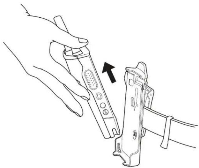
natural_image
Line drawing of a hand holding a handheld device with an arrow pointing to the device (no text or symbols present)6.13
natural_image
Hand icon with finger pressing a circular button (no text or symbols)natural_image
Illustration of two fingers interacting with a green star and circular button (no text or symbols)natural_image
Hand icon with green circular target and finger pointing at it (no text or symbols)natural_image
Hand pointing at a green star icon with a circular arrow (no text or symbols)Capítulo 7
natural_image
Green rectangular background with a small icon and a small grid bar on the right (no text or symbols)- Chamada privada
- Alerta de Chamada.
- Chamada seletiva
- Inserir cerca geográfica
7.2.5
Indicadores da barra de luz
Azul-claro Aberto/em espera
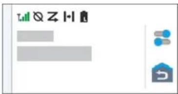
natural_image
Simple diagram with a gray rectangle, two blue dots and one gray house icon, no text or symbols present.Capítulo 8
Em Settings, toque em Connected devices →
10.3.7
4.3 IP Site Connect....29
MOTOROLA, MOTO, MOTOROLA SOLUTIONS, and the Stylized M Logo are trademarks or registered trademarks of Motorola Trademark Holdings, LLC and are used under license. Google, Android, Google Play, Youtube, and other marks are trademarks of Google LLC. All other trademarks are the property of their respective owners.
ライセンスの権利
© 2024 Motorola Solutions, Inc. All Rights Reserved
法的および準拠に関する声明
供給元の適合宣言
供給元の適合宣言
Per FCC CFR 47 Part 2 Section 2.1077(a)

責任者
名前: Motorola Solutions, Inc.
住所: 2000 Progress Pkwy, Schaumburg, IL.60196
- https://youtu.be/cYjxoUNCXZo
- https://www.motorolasolutions.com/newsroom/press-releases/recommended-cleaning-and-disinfecting-guidelines-for-our-radios-body-worn-c.html
バッテリの接触面のクリーニング
natural_image
Black motorola device with antenna and control panel (no visible text or symbols on device body)充電器の LED が点灯します。

注:
6.9
音量の調節
手順:
下記の操作のいずれかを実行します。
natural_image
Line drawing of a hand holding a handheld device with an arrow indicating the process (no text or symbols present)natural_image
Line drawing of a hand holding a walkie-talkie device with an arrow pointing to the grip (no text or symbols present)natural_image
Line drawing of a hand holding a handheld device with a dashed circular arrow indicating rotation (no text or symbols)natural_image
Line drawing of a hand holding a handheld device with an arrow pointing to the device (no text or symbols present)6.13
画面キーボードの概要
表 8: 画面キーボードの概要
natural_image
Hand icon with finger pressing a circular button (no text or symbols)natural_image
Illustration of two fingers pointing at a green star and circular target (no text or symbols)natural_image
Hand icon with green circular target and finger pointing at it, no text or symbols presentnatural_image
Hand icon pointing at a green star with a circular arrow overlay (no text or symbols)章7
ホーム画面の概要
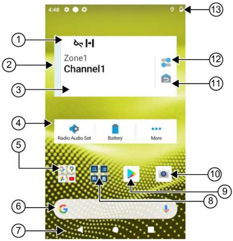
表 10: ホーム画面の概要
natural_image
Green rectangular background with a small icon and a small vertical bar on the right (no text or symbols)黄色 通信着信中
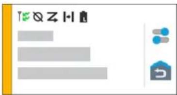
赤色 通信送信中
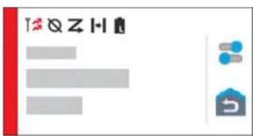
灰色 プログラムされていません
カラー 通信状態
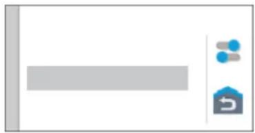
natural_image
Simple diagram with a gray rectangle, blue dots, and a house icon (no text or symbols)章8
一般無線機設定
4.3 IP Site Connect....27
MOTOROLA, MOTO, MOTOROLA SOLUTIONS, and the Stylized M Logo are trademarks or registered trademarks of Motorola Trademark Holdings, LLC and are used under license. Google, Android, Google Play, Youtube, and other marks are trademarks of Google LLC. All other trademarks are the property of their respective owners.
라이선스 권한
© 2024 Motorola Solutions, Inc. All Rights Reserved
□□□□□ □□□ □□□
FCC CFR 47 Part 2 Section 2.1077(a)

□□□□□
□: Motorola Solutions, Inc.
□: 2000 Progress Pkwy, Schaumburg, IL. 60196
□□□: 1-800-927-2744
□□□ □□□ □□□ □□□□□.
□□ □□: MSLB-MKZ900, MSLB-MKZ920
□□ □□□ □□□□□.
FCC Part 15, Subpart B, Section 15.107(a), 15.107(d), 15.109(a)
Class B □□□ □□
FCC Part 150
1.
2.

□□:
- https://youtu.be/cYjxoUNCXZo
- https://www.motorolasolutions.com/newsroom/press-releases/recommended-cleaning-and-disinfecting-guidelines-for-our-radios-body-worn-c.html
배터리 접촉부 세척
natural_image
Black motorola device with antenna and control panel (no visible text or symbols on body)충전기 LED가 켜집니다.

참고:
6.9
볼륨 조절
절차:
다음 작업 중 하나를 수행합니다.
natural_image
Line drawing of a hand holding a device with an arrow indicating the process (no text or symbols present)natural_image
Line drawing of a hand holding a walkie-talkie device with a black arrow pointing to the handle (no text or symbols present)휴대 케이스에서 무전기 분리
절차:
natural_image
Line drawing of a hand holding a handheld device with a dashed circular arrow indicating motion (no text or symbols)natural_image
Line drawing of a hand holding a device with an arrow pointing to a separate device (no text or symbols present)6.13
화상 키보드 개요
표 8: 화상 키보드 개요
natural_image
Hand icon with finger pressing a circular button (no text or symbols)natural_image
Illustration of two fingers pointing at a green circular button with a star (no text or symbols)natural_image
Hand icon with green circular target and finger pointing upward (no text or symbols)손가락 모으기
natural_image
Hand icon pointing at a green star with circular background (no text or symbols)장 7
홈 화면 개요
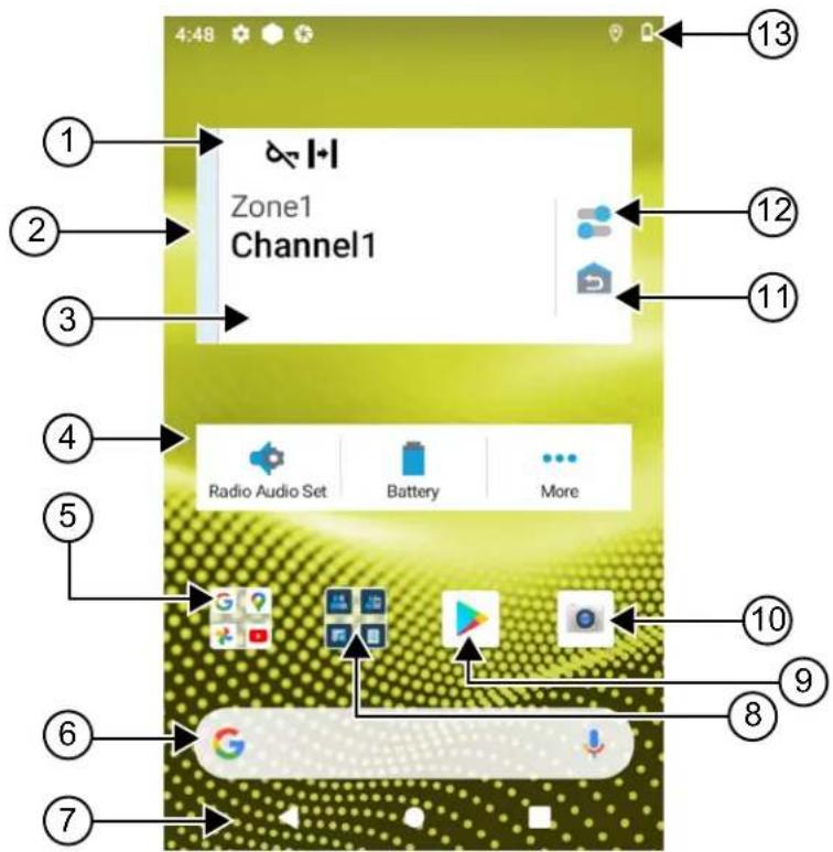
표 10: 흙 화면 개요
노란색 수신 통화
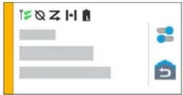
빨간색 송신 통화
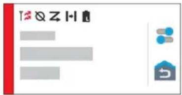
회색 프로그래밍되지 않음
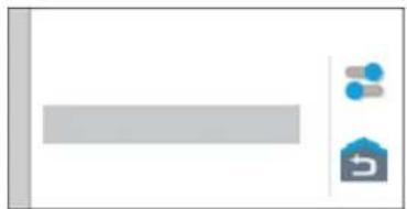
natural_image
Simple diagram with a gray rectangle and two icons: a blue dot labeled 'B' and a house with a circular arrow (no text or symbols)장 8
일반 무전기 설정
4.3 IP Site Connect....30
8.11 USB-Desensing....66
8.12 Akku....66
MOTOROLA, MOTO, MOTOROLA SOLUTIONS, and the Stylized M Logo are trademarks or registered trademarks of Motorola Trademark Holdings, LLC and are used under license. Google, Android, Google Play, Youtube, and other marks are trademarks of Google LLC. All other trademarks are the property of their respective owners.
Lizenzrechte
© 2024 Motorola Solutions, Inc. All Rights Reserved
Name: Motorola Solutions, Inc.
Adresse: 2000 Progress Pkwy, Schaumburg, IL. 60196, USA
Telefonnummer: 1-800-927-2744
Modellname: MSLB-MKZ900, MSLB-MKZ920
- https://youtu.be/cYjxoUNCXZo
- https://www.motorolasolutions.com/newsroom/press-releases/recommended-cleaning-and-disinfecting-guidelines-for-our-radios-body-worn-c.html
natural_image
Black motorola device with antenna and control panel (no visible text or symbols on device body)6.9
natural_image
Line drawing of a hand holding a device with an arrow indicating the process (no text or symbols present)natural_image
Line drawing of a hand holding a walkie-talkie device with a cable, showing no text or symbolsnatural_image
Line drawing of a hand holding a handheld device with a dashed circular arrow indicating rotation (no text or symbols)MN006217A01-AK
natural_image
Line drawing of a hand holding a handheld device with an arrow pointing to the device (no text or symbols present)6.13