SMD 24 A1 - Interdental brush NEVADENT - Free user manual and instructions
Find the device manual for free SMD 24 A1 NEVADENT in PDF.

User questions about SMD 24 A1 NEVADENT
0 question about this device. Answer the ones you know or ask your own.
Ask a new question about this device
Download the instructions for your Interdental brush in PDF format for free! Find your manual SMD 24 A1 - NEVADENT and take your electronic device back in hand. On this page are published all the documents necessary for the use of your device. SMD 24 A1 by NEVADENT.
USER MANUAL SMD 24 A1 NEVADENT
natural_image
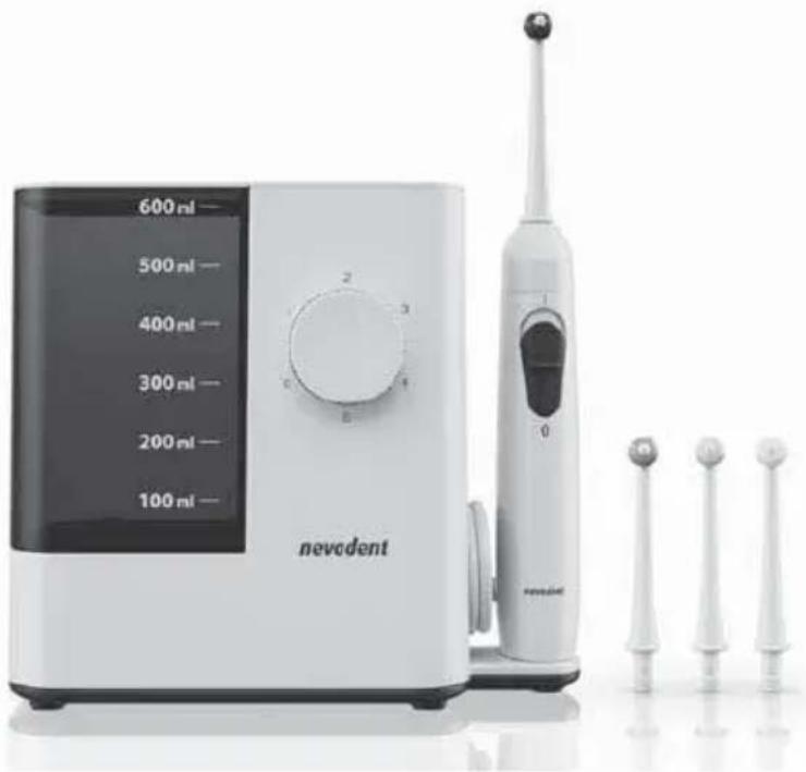
White nevolet appliance with digital display and three toothbrushes (no visible text or symbols)WATER JET FLOSSER / MUNDDUSCHE HYDROPULSEUR SMD 24 A1
GB IE
WATER JET FLOSSER
Operating instructions and safety instructions
FR BE
HYDROPULSEUR
Before reading, unfold the page containing the illustrations and familiarise yourself with all functions of the device.
DE AT CH
GB / IE Operating instructions and safety instructions Page 1
Information about these operating instructions .... 2
Copyright 2
Intended use 2
Safety information 3
Package contents and transport inspection 5
Description of the appliance 6
Before first use ....7
Requirements for the set-up location 7
Wall mounting 7
Handling and operation 8
Attaching/removing nozzle attachments 8
Adjusting the nozzle control 9
Using the oral irrigator 10
After use....12
Cleaning and care 13
Storage 13
Ordering replacement parts 14
Troubleshooting 15
Disposal 16
Disposal of the appliance 16
Disposal of the packaging 16
Appendix 17
Technical data 17
Kompernass Handels GmbH warranty 17
Service 19
Importer 19
Introduction
Information about these operating instructions
Congratulations on the purchase of your new appliance.
You have selected a high-quality product. The operating instructions are part of this product. They contain important information about safety, usage and disposal. Before using the product, please familiarise yourself with all operating and safety instructions. Use the product only as described and for the range of applications specified. Please also pass these operating instructions on to any future owner.
Copyright
This documentation is protected by copyright.
Any copying or reproduction, including in the form of extracts, or any reproduction of images (even in a modified state), is permitted only with the written authorisation of the manufacturer.
Intended use
This appliance is intended exclusively for dental care and mouth hygiene in humans. The appliance is not intended for use in industrial or medical environments. It is not suitable for animal care. This appliance is intended solely for use in private households. It is not intended for any other purpose nor for use beyond the scope described.
Claims of any kind for damage resulting from misuse, incompetent repairs, unauthorised modification or the use of unauthorised replacement parts will not be accepted. The operator bears sole liability.
Safety information

- Connect the appliance only to a properly installed and easily accessible mains power socket supplying a mains power voltage of 100–240 V \~, 50/60 Hz.
▶ Ensure that the power cable is not damaged. Keep it out of hot areas and route it in such a way that it cannot be damaged.
Before use, check the appliance for visible external damage. Never use the appliance if the cable, plug or housing are damaged.
▶ To avoid potential risks, if the appliance power cable is damaged, it must be replaced by the manufacturer, its customer service or by a qualified technician.
▶ Have all repairs carried out by a specialist workshop. Under no circumstances should you open the appliance yourself. Repairs that are not carried out by a specialist workshop could lead to physical injuries.
▶ Do not use the appliance in the vicinity of a bathtub/shower or a sink filled with water. The proximity of moisture presents a danger even when the appliance is switched off.
▶ Never touch the appliance if it has fallen into water. Always disconnect the power plug from the power socket first!
▶ Never immerse the connected appliance in water or other liquids.
▶ Never touch the power cable or the appliance with wet or damp hands.

▶ Ensure that the power cable can never become wet or damp during operation. Route the power cable in such a way that it cannot become trapped or damaged in any other way.
- Do not use the power cable with an extension cable; connect the power cable directly to a power socket.

WARNING! RISK OF INJURY!
- Do not change any accessories while the appliance is switched on.
▶ Always store the appliance indoors. To prevent accidents, keep the appliance in a dry location when not in use.
▶ Oral irrigators may be used by children over the age of 8 and by persons with reduced physical, sensory or mental capabilities or lack of experience and/or knowledge if they are supervised.
▶ Switch off the appliance before you put it down or change accessories. - Lay the power cable so that nobody can step on it or trip over it.
▶ Always pull out the plug before cleaning the appliance. Do not pull on the power cable. Always grip the power plug to disconnect the appliance from the power supply.

ATTENTION! PROPERTY DAMAGE!
▶ Use only accessories recommended by the manufacturer.
- Do not make any unauthorised modifications or alterations to the appliance.
▶ Never put down the appliance next to radiators, ovens or other heated appliances or surfaces.
The appliance may only be used with cold or lukewarm tap water up to a maximum of 40^ C. If necessary, add a few drops of mouthwash. The water tank should never be completely filled with additives such as mouthwash or mouth rinse. These can damage the appliance.
Package contents and transport inspection
◆ Remove all parts of the appliance and the operating instructions from the carton.
◆ Remove all packaging materials and any films and labels.

DANGER
Do not allow children to play with packaging materials. There is a risk of suffocation! The package contents include the following components (see fold-out page for illustrations):
● Water jet flosser (main unit with hand unit and water tank)
• 4 nozzle attachments
- 2 wall plugs (5 mm)
- 2 screws (3 mm)
- Operating instructions (not shown)
NOTE
▶ Check the package for completeness and for signs of visible damage.
▶ If the delivery is incomplete or damage has occurred as a result of defective packaging or during transport, contact the service hotline (see section Service).
Description of the appliance
(See fold-out page for illustrations)
① Nozzle control
② Nozzle attachment
③ On/Off switch for the water jet I/O
4 Hand unit
⑤ Cradle for hand unit
6 Hangers
7 Locking pin
8 Screw
9 Wall plug
10 Release button for nozzle attachment
⑪ Power cable (with mains plug)
12 Main unit
13 Water tank
15 Water tank lid
17 Storage compartment lid
14 Rotary switch (On/Off switch and water pressure control)
16 Storage compartment for nozzle attachments
Before first use
Requirements for the set-up location
To ensure safe and trouble-free operation of the appliance, the set-up location must fulfil the following requirements:
The appliance may only be operated free-standing if used in dry rooms. The set-up location must be a horizontal, level and stable surface.
In damp rooms, especially in the vicinity of water, the appliance must be firmly fixed to the wall to protect it from falling into water.
The mains power socket must be easily accessible so that the power cable can be quickly disconnected in an emergency.
Wall mounting
NOTE
Before mounting to the wall, make sure that there are no electric cables, wires or pipes running behind the wall surface where you plan to hang the appliance.
-
Mark two drill holes on the wall 7.2 cm apart and drill the marked holes with a 5 mm bit. Ensure that there is a power socket in the immediate vicinity.
-
Push the two supplied wall plugs ⑨ into the drilled holes and screw the two supplied screws ⑧ into the wall plugs ⑨. Take care that the screws ⑧ still protrude about 3 mm out of the holes.
-
On the back side of the appliance, the right hanger ⑥ has a locking pin ⑦ to prevent the appliance from coming free of the screws ⑧. Press the locking pin ⑦ back somewhat until you hear a click. Then pull the locking pin ⑦ down slightly out of the hanger ⑥ (see Fig. 1).
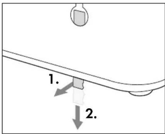
Fig. 1
-
Push the appliance onto the screws ⑧ so that the screws ⑧ enter into the hangers ⑥ on the back side of the appliance. Then press the appliance downward so that the screws ⑧ slide into the rails of the hangers ⑥ and the appliance rests firmly on the screws ⑧.
-
Slide the locking pin ⑦ upwards until it audibly engages with the hanger ⑥.
-
Plug the mains plug of the power cable ⑪ into a socket.
Handling and operation
Attaching/removing nozzle attachments
NOTE
▶ If used daily, replace the nozzle attachments ^2 after no more than six months.
▶ Use only original nozzle attachments ^2 . Information on ordering replacement nozzle attachments ^2 can be found in the section Ordering replacement parts.
Make certain that the appliance is switched off before attaching or removing the nozzle attachment ②.
Fit a nozzle attachmen onto the hand unit 4. Press the nozzle attachment into the opening until the nozzle attachment 2 audibly engages in the hand unit 4. Ensure that the guide tab on the lower end of the nozzle attachment 2 is aligned with the corresponding groove in the opening on the hand unit 4 (see Fig. 2).
To remove the nozzle attachment 2, press the release button 10 on the hand unit 4 and then pull the nozzle attachment 2 out of the hand unit 4 (see Fig. 3).
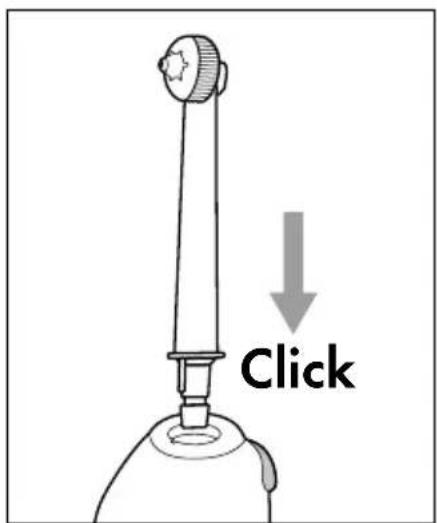
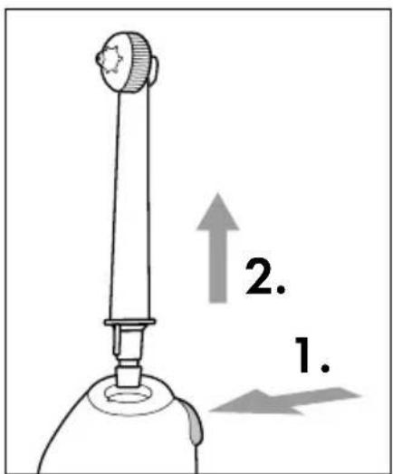
Fig. 2 Fig. 3
Adjusting the nozzle control
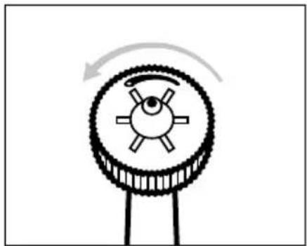
You can use the nozzle control ① on the head of the nozzle attachment ② to switch between two different nozzle functions:
Turn the nozzle control ① anti-clockwise with your fingers to obtain a single jet for targeted removal of food remnants from hard-to-reach areas (see Fig. 4 and 5).
natural_image
Diagram of a mechanical gear or pulley system with rotational arrow indicating clockwise motion (no text or symbols)
natural_image
Illustration of a tooth being examined with a magnifying glass, showing the tooth's magnified view (no text or symbols present)Fig. 4 Fig. 5
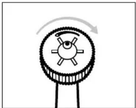
Turn the nozzle control ① clockwise with your fingers to obtain multiple jets for massaging the gums (see Fig. 6 and 7).
natural_image
Diagram of a mechanical gear mechanism with rotational arrow (no text or symbols)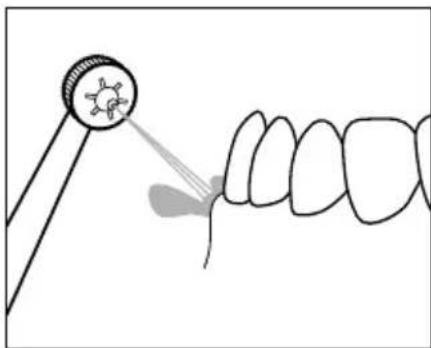
natural_image
Illustration of a dental procedure showing a tooth being pointed at a circular target (no text or symbols present)Fig. 6 Fig. 7
Using the oral irrigator

CAUTION - PROPERTY DAMAGE!
▶ Fill the water tank ^13 with pure tap water. If necessary, add a few drops of mouthwash. The water tank ^13 should never be completely filled with additives such as mouthwash or mouth rinse.
▶ Use only cold or lukewarm water with a maximum temperature of 40^ C. Do not fill the water tank ⑬ with hot water.
NOTE
▶ Use of the appliance is not a replacement for daily tooth cleaning with a toothbrush and toothpaste. Use the appliance only as a supplement to daily tooth cleaning with toothbrush and toothpaste.
▶ Only use the appliance for a maximum of 2 minutes or only long enough to use up one full tank of water (600 ml). One full tank of water (600 ml) is sufficient to operate the appliance for about 150 seconds at level 1 or about 110 seconds at level 5.
The unfamiliar stimulation may cause some gum bleeding at first, which is not unusual. If this continues for more than two weeks, you should consult your dentist.
- Consult your dentist before using the appliance if you suffer from severe periodontitis, have injuries or abscesses in the mucous membrane of the oral cavity or underwent dental surgery within the last two months.
Remove the water tank from the main unit and open the lid of the water tank. Fill the water tank with cold or lukewarm water. Take care not to fill the water tank past the maximum fill mark of 600 ml. Then close the water tank again with the lid and place the water tank in the main unit.
Fit a nozzle attachment ② onto the hand unit ④. Press the nozzle attachment ② into the opening until the nozzle attachment ② audibly engages in the hand unit ④. Ensure that the guide tab on the lower end of the nozzle attachment ② is aligned with the corresponding groove in the opening on the hand unit ④.
Switch on the main unit 12 by setting the rotary switch 14 to the desired water pressure level 1 - 5 (1 = gentle, 5 = strong).
Open your mouth slightly and insert the nozzle attachment ②. Bend over a washbasin to allow the water to run into the basin.
NOTE
▶ Begin with a lower level to allow your gums to become accustomed to the water jet. Increase the strength of the water jet in stages. If the pressure is uncomfortable, select a lower level again.
To avoid splashes, do not switch on the hand until it is in your mouth.
Switch on the hand unit ④ by moving the On/Off switch for the water jet I/O ③ on the hand unit ④ to I.
Direct the water jet at the gaps between your teeth and the edges of your teeth to clean them. Position the nozzle attachment ② so that the water jet can rinse the food remnants away from the gums (see Fig. 8). Move the nozzle attachment ② slowly along the edge of the teeth from gap to gap (see Fig. 9). Clean all the front and back sides of your teeth in this way.
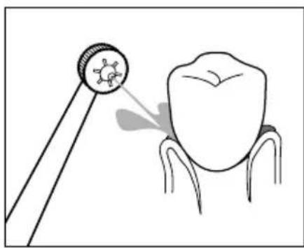
natural_image
Illustration of a dental tool projecting a tooth to the upper portion of a tooth (no text or symbols present)
natural_image
Diagram showing a dental tool interacting with teeth, illustrating tooth alignment and tooth movement (no text or symbols)Fig. 8 Fig. 9
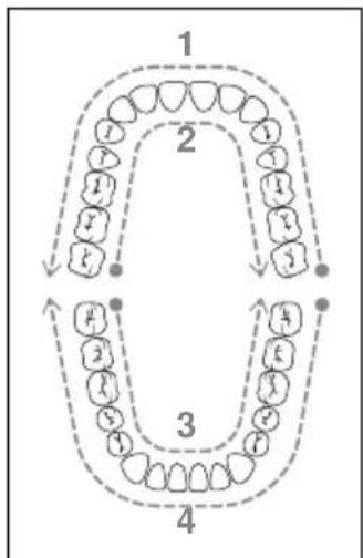
You can use the image below as a guide for the order of cleaning (see Fig. 10). The numbers in the image indicate the order in which to clean the different areas:
flowchart
graph TD
    A["Step 1: Finger"] --> B["Step 2: Head"]
    B --> C["Step 3: Tail"]
    C --> D["Step 4: Tooth"]
    D --> A
    style A fill:#f9f,stroke:#333
    style B fill:#ccf,stroke:#333
    style C fill:#cfc,stroke:#333
    style D fill:#fcc,stroke:#333
- Front of upper teeth
- Back of upper teeth
- Back of lower teeth
- Front of lower teeth
Fig. 10
- Start at the front side of your upper molars and move the nozzle attachment ② along the edges of the teeth from one side to the other. Repeat this process for the back of the upper teeth and for the back and front of the lower teeth.
After use
NOTE
▶ Empty the water tank ^13 after every use to prevent the growth of germs and bacteria.
-
Switch the On/Off switch for the water jet I/O ③ on the hand unit ④ to 0 before removing the nozzle attachment ② from your mouth.
-
Set the rotary switch ⑭ on the main unit ⑫ to 0.
-
Remove the water tank ⑬ from the main unit ⑫ and open the lid ⑮ of the water tank ⑬. Pour the remaining water out of the water tank ⑬ into the washbasin.
-
Close the lid ⑮ of the water tank ⑬ and place the water tank ⑬ back in the main unit ⑫.
-
Set the rotary switch 14 on the main unit 12 to 5 and hold the hand unit 4 over the washbasin.
-
Switch the On/Off switch for the water jet I/O ③ on the hand unit ④ to I to clear any remaining water from the line and rinse out the nozzle attachment ②.
-
Switch the On/Off switch for the water jet I/O jet ③ on the hand unit ④ to 0.
-
Set the rotary switch ⑭ on the main unit ⑫ to 0.
-
Press the release button ⑩ on the hand unit ④ and then pull the nozzle attachment ② out of the hand unit ④.
-
Rinse the nozzle attachment ② under running water.
-
Dry the nozzle attachment ② and place it in one of the spots in the storage compartment ⑯.
-
Place the hand unit ④ in the cradle ⑤ on the main unit ⑫.
Cleaning and care

DANGER - ELECTRIC SHOCK!
▶ Always pull out the plug before cleaning the appliance. There is a risk of electric shock!
The appliance must be completely dry before connecting it to the socket again.

Never submerge the main unit ⑫ or the hand unit ④ in water or other liquids!

CAUTION - PROPERTY DAMAGE!
▶ Do not use any aggressive cleaning agents or solvents. These could damage the plastic surfaces of the appliance.
Remove the nozzle attachmen ^2 from the hand unit 4 and rinse it off under running water.
Clean the main unit 12 and the hand unit 4 with a soft, slightly damp cloth. For stubborn soiling add a little mild detergent to the cloth. Afterwards, wipe off with a cloth moistened only with pure water. Then dry off the main unit 12 and the hand unit 4 with a dry cloth.
Remove the water tank 13 from the main unit 12 and open the lid 15 of the water tank 13. Rinse the water tank 13 under running water. After cleaning, pour the remaining water out of the water tank 13 into the washbasin.
If you do not intend to use the appliance for a longer period, remove the lid from the water tank ⑬. Allow the water tank ⑬ to dry completely in air before placing it back in the main unit ⑫.
Storage
♦ Disconnect the appliance from the power supply by pulling the plug of the switched-off appliance from the socket.
◆ Remove any water from the appliance and allow the appliance to dry completely (see section Cleaning and care).
◆ Store the appliance in a dry and dust-free location out of direct sunlight.
Ordering replacement parts
You can order replacement parts for this product on the Internet at www.kompernass.com.

Scan this QR code with your smartphone or tablet. You can use this QR code to go directly to our website www.kompernass.com to view and order the available replacement parts.
NOTE
▶ If you have problems with your online order, you can contact our service centre by phone or e-mail (see section Service).
▶ Please always quote the article number (e.g. 123456_7890) when ordering. You can find it on the title page of these operating instructions.
▶ Please note that online ordering of replacement parts is not possible for all countries.
Troubleshooting
The following table will help you to identify and rectify minor malfunctions. If the solutions presented below do not resolve the problem, please contact Customer Service (see section Service).
| Fault Cause Remedy | ||
| No water jet comes out of the nozzle attachment 2. | The appliance is not switched on. | Make sure that the appliance is properly connected to the power supply.Set the rotary switch 14 to the desired water pressure level 1-5.Switch the On/Off switch for the water jet 1/0 3 on the hand unit 4 to 1. |
| The mains plug is not plugged in. | Insert the plug into a mains power socket. | |
| The socket is not supplying any power. | Check the house mains fuse. | |
| The nozzle attachment 2 is defective. | Replace the nozzle attachment 2(see section Attaching/removing nozzle attachments) | |
| The water tank 13 is empty. | Fill the water tank 13 with tap water (see section Using the oral irrigator). | |
| The appliance is defective. | Switch off the appliance and pull out the mains plug.Contact Customer Service(see section Service). | |
| The water pressure cannot be set correctly or is too weak. | The water tank 13 is not seated properly in the main unit 12. | Place the water tank 13 in the main unit 12 and press the water tank 13 down until it sits firmly in the main unit 12. |
| The water tank 13 has a leak. | The water tank 13 is not seated properly in the main unit 12. | Place the water tank 13 in the main unit 12 and press the water tank 13 down until it sits firmly in the main unit 12. |
| The valve of the water tank 13 is defective. | Switch off the appliance and pull out the mains plug.Contact Customer Service(see section Service). | |
| The nozzle attachment 2 has a leak. | The nozzle attachment 2 is not properly attached to the hand unit 4. | Attach the nozzle attachment 2 properly to the hand unit 4 (see section Attaching/removing nozzle attachments). |
| The nozzle attachment 2 is defective. | Replace the nozzle attachment 2 (see section Attaching/removing nozzle attachments). |
Disposal
Disposal of the appliance
The adjacent symbol of a crossed-out wheelie bin means that this appliance is subject to Directive 2012/19/EU. This directive states that the product may not be disposed of in normal household waste at the end of its useful life, but must be taken to a specially set-up collection point, recycling depot or disposal company.
This disposal is free of charge for the user. Protect the environment and dispose of this appliance properly.

Your local community or municipal authorities can provide information on how to dispose of the worn-out product.

The product is recyclable, subject to extended producer responsibility and is collected separately.
Disposal of the packaging

The packaging materials have been selected for their environmental compatibility and ease of disposal and are therefore recyclable.
Dispose of packaging materials that are no longer needed in accordance with applicable local regulations.
Dispose of the packaging in an environmentally friendly manner. Note the labelling on the packaging and separate the packaging material components for disposal, if necessary. The packaging material is labelled with abbreviations (a) and numbers (b) with the following meanings:
1-7: plastics, 20-22: paper and cardboard, 80-98: composites.
Appendix
Technical data
| Power supply 100–240 V ~ (AC), 50/60 Hz | |
| Power consumption 24 W | |
| Protection class | II/☐(double insulation) |
| Protection type IPX4 (protected against water splashes from any direction) | |
NOTE
▶ No user action is required to switch the product between 50 and 60 Hz. The product switches automatically to either 50 or 60 Hz.
This appliance has a 3-year warranty valid from the date of purchase. If this product has any faults, you, the buyer, have certain statutory rights. Your statutory rights are not restricted in any way by the warranty described below.
Warranty conditions
The warranty period starts on the date of purchase. Please keep your receipt in a safe place. This will be required as proof of purchase.
If any material or manufacturing fault occurs within three years of the date of purchase of the product, we will either repair or replace the product for you or refund the purchase price (at our discretion). This warranty service requires that you present the defective appliance and the proof of purchase (receipt) within the three-year warranty period, along with a brief written description of the fault and of when it occurred.
If the defect is covered by the warranty, your product will either be repaired or replaced by us. The repair or replacement of a product does not signify the beginning of a new warranty period.
Warranty period and statutory claims for defects
The warranty period is not prolonged by repairs effected under the warranty. This also applies to replaced and repaired components. Any damage and defects present at the time of purchase must be reported immediately after unpacking. Repairs carried out after expiry of the warranty period shall be subject to a fee.
Scope of the warranty
This appliance has been manufactured in accordance with strict quality guidelines and inspected meticulously prior to delivery.
The warranty covers material faults or production faults. The warranty does not extend to product parts subject to normal wear and tear or to fragile parts which could be considered as consumable parts such as switches, batteries or parts made of glass.
The warranty does not apply if the product has been damaged, improperly used or improperly maintained. The directions in the operating instructions for the product regarding proper use of the product are to be strictly followed. Uses and actions that are discouraged in the operating instructions or which are warned against must be avoided.
This product is intended solely for private use and not for commercial purposes. The warranty shall be deemed void in cases of misuse or improper handling, use of force and modifications / repairs which have not been carried out by one of our authorised Service centres.
Warranty claim procedure
To ensure quick processing of your case, please observe the following instructions:
■ Please have the till receipt and the item number (e.g. IAN 123456_7890) available as proof of purchase.
■ You will find the item number on the type plate on the product, an engraving on the product, on the front page of the operating instructions (below left) or on the sticker on the rear or bottom of the product.
If functional or other defects occur, please contact the service department listed either by telephone or by e-mail.
■ You can return a defective product to us free of charge to the service address that will be provided to you. Ensure that you enclose the proof of purchase (till receipt) and information about what the defect is and when it occurred.

You can download these instructions along with many other manuals, product videos and installation software at www.lidl-service.com.
This QR code will take you directly to the Lidl service page (www.lidl-service.com) where you can open your operating instructions by entering the item number (IAN) 359279_2007.
Service
GB Service Great Britain
Tel.: 0800 404 7657
E-Mail: kompernass@lidl.co.uk
IE ServiceIreland
Tel.: 1890 930 034
(0,08 EUR / Min., (peak))
(0,06 EUR / Min., (off peak))
E-Mail: kompernass@lidl.ie
IAN 359279_2007
Importer
Please note that the following address is not the service address. Please use the service address provided in the operating instructions.
KOMPERNASS HANDELS GMBH
BURGSTRASSE 21
44867 BOCHUM
GERMANY
www.kompernass.com
Inhaltsverzeichnis
Einleitung 22
natural_image
Diagram of a mechanical gear or wheel with a rotating arrow indicating clockwise motion (no text or symbols)
natural_image
Illustration of a dental tool interacting with a tooth, showing the tooth being pointed at its base (no text or symbols present)Abb.4 Abb.5
natural_image
Diagram of a mechanical gear mechanism with rotational arrow (no text or symbols)
natural_image
Illustration of a dental procedure showing a tooth being injected from a magnifying glass (no text or symbols present)Abb.6 Abb.7
natural_image
Illustration of a dental tool projecting a tooth with a molecular structure (no text or symbols)
natural_image
Illustration of a dental procedure showing tooth alignment with a tool (no text or symbols)Abb.8 Abb.9
KOMPERNASS HANDELS GMBH
BURGSTRASSE 21
44867 BOCHUM
DEUTSCHLAND
www.kompernass.com
Table des matières
Introduction 42
natural_image
Diagram of a mechanical gear or wheel with a rotating arrow indicating clockwise motion (no text or symbols)
natural_image
Illustration of a dental tool interacting with a tooth, showing the tooth being pointed at its base (no text or symbols present)Fig. 4 Fig. 5
natural_image
Diagram of a mechanical gear mechanism with rotational arrow (no text or symbols)
natural_image
Illustration of a dental procedure showing a tooth being injected from a magnifying glass (no text or symbols present)Fig. 6 Fig. 7
natural_image
Illustration of a dental tool projecting a tooth with a molecular structure (no text or symbols)
natural_image
Illustration of a dental procedure showing tooth alignment with a tool (no text or symbols)Fig. 8 Fig. 9
flowchart
graph TD
    A["Stage 1: Circular Nodes"] --> B["Stage 2: Dashed Arrow"]
    B --> C["Stage 3: Circular Nodes"]
    C --> D["Stage 4: Dashed Arrow"]
    D --> A
Fig. 10
KOMPERNASS HANDELS GMBH
BURGSTRASSE 21
44867 BOCHUM
ALLEMAGNE
www.kompernass.com
Inhoud
Inleiding 64
⚠ WAARSCHUWING! LETSELGEVAAR!
natural_image
Diagram of a mechanical gear or wheel with a rotating arrow indicating clockwise motion (no text or symbols)
natural_image
Illustration of a dental tool interacting with a tooth, showing the tooth being pointed at its base (no text or symbols present)Afb. 4 Afb. 5
natural_image
Diagram of a mechanical gear mechanism with rotational arrow (no text or symbols)
natural_image
Illustration of a dental procedure showing a tooth being injected from a magnifying glass (no text or symbols present)Afb. 6 Afb. 7
natural_image
Illustration of a dental tool projecting a tooth with a magnified inset showing the tooth's surface (no text or symbols)
natural_image
Illustration of a dental procedure showing tooth alignment with a tool (no text or symbols)Afb. 8 Afb. 9
KOMPERNASS HANDELS GMBH
BURGSTRASSE 21
44867 BOCHUM
DUITSLAND
www.kompernass.com
Obsah
Úvod....84
POZOR! HMOTNÉ ŠKODY!
natural_image
Diagram of a mechanical gear or wheel with a rotating arrow indicating clockwise motion (no text or symbols)
natural_image
Illustration of a dental tool interacting with a tooth, showing the tooth being pointed at its base (no text or symbols present)Obr. 4 Obr. 5
natural_image
Diagram of a mechanical gear or wheel with a rotating arrow indicating rotational motion (no text or symbols)
natural_image
Illustration of a dental procedure showing a tooth being injected from a magnifying glass (no text or symbols present)Obr. 6 Obr. 7
natural_image
Illustration of a tooth being measured by a dental mirror, showing the tooth's magnified view (no text or symbols present)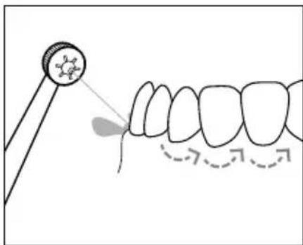
natural_image
Illustration of a dental procedure showing a tooth being pointed at a mirror and then forming a curved line (no text or symbols present)Obr. 8 Obr. 9
flowchart
graph TD
    A["Stage 1: In- teeth with teeth at 10°"] --> B["Stage 2: In- teeth with teeth at 30°"]
    B --> C["Stage 3: In- teeth with teeth at 40°"]
    C --> D["Stage 4: In- teeth with teeth at 50°"]
Obr. 10
KOMPERNASS HANDELS GMBH
BURGSTRASSE 21
44867 BOCHUM
NĚMECKO
www.kompernass.com
Spis treści
W step 104
natural_image
Diagram of a mechanical gear or wheel with a rotating arrow indicating clockwise motion (no text or symbols)
natural_image
Illustration of a dental tool interacting with a tooth, showing the tooth being pointed at its base (no text or symbols present)Rys. 4 Rys. 5
natural_image
Diagram of a mechanical gear or wheel with a rotating arrow indicating rotational motion (no text or symbols)
natural_image
Illustration of a dental procedure showing a tooth being injected into a tooth with a magnified inset (no text or symbols)Rys. 6 Rys. 7
natural_image
Illustration of a dental tool projecting a tooth model into a tooth (no text or symbols present)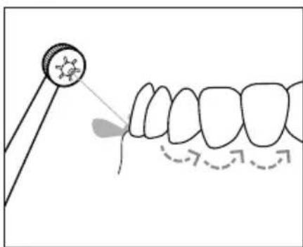
natural_image
Illustration of a dental procedure showing a tooth being used to apply using a tool, with arrows indicating direction (no text or symbols present)Rys. 8 Rys. 9
flowchart
graph TD
    A["Step 1: Teeth at top"] --> B["Step 2: Teeth at middle"]
    B --> C["Step 3: Teeth at bottom"]
    C --> D["Step 4: Teeth at bottom"]
    style A fill:#f9f,stroke:#333
    style B fill:#ccf,stroke:#333
    style C fill:#cfc,stroke:#333
    style D fill:#fcc,stroke:#333
Rys. 10
KOMPERNASS HANDELS GMBH
BURGSTRASSE 21
44867 BOCHUM
NIEMCY
www.kompernass.com
Obsah
Úvod....124
natural_image
Diagram of a mechanical gear or cam mechanism with rotational arrow (no text or symbols)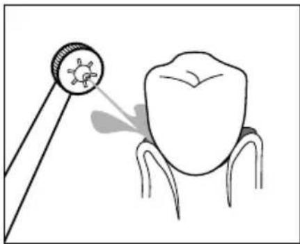
natural_image
Illustration of a tooth being examined with a magnifying glass, showing the tooth's magnified view (no text or symbols present)Obr. 4 Obr. 5
natural_image
Diagram of a mechanical gear mechanism with rotational arrow (no text or symbols)
natural_image
Illustration of a dental procedure showing a tooth being pointed at a circular target (no text or symbols present)Obr. 6 Obr. 7
natural_image
Illustration of a dental tool projecting a tooth to the upper portion of a tooth (no text or symbols present)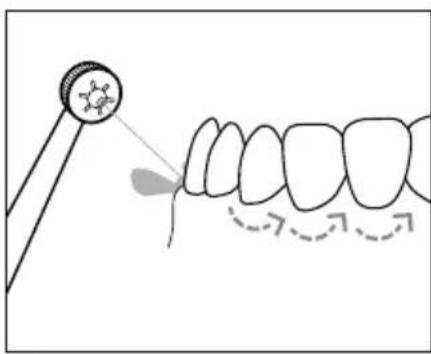
natural_image
Diagram showing a dental tool interacting with teeth, illustrating tooth alignment and tooth movement (no text or symbols)Obr. 8 Obr. 9
flowchart
graph TD
    A["Step 1: Teeth at top"] --> B["Step 2: Teeth at middle"]
    B --> C["Step 3: Teeth at bottom"]
    C --> D["Step 4: Teeth at bottom"]
    style A fill:#f9f,stroke:#333
    style B fill:#ccf,stroke:#333
    style C fill:#cfc,stroke:#333
    style D fill:#fcc,stroke:#333
Obr. 10
KOMPERNASS HANDELS GMBH
BURGSTRASSE 21
44867 BOCHUM
NEMECKO
www.kompernass.com
Índice
Introducción....144
natural_image
Diagram of a mechanical gear or wheel with a rotating arrow indicating clockwise motion (no text or symbols)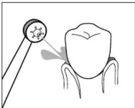
natural_image
Illustration of a dental tool interacting with a tooth, showing the tooth being pointed at its base (no text or symbols present)Fig. 4 Fig. 5
natural_image
Diagram of a mechanical gear or wheel with a rotating arrow indicating rotational motion (no text or symbols)
natural_image
Illustration of a dental procedure showing a tooth being injected from a magnifying glass (no text or symbols present)Fig. 6 Fig. 7
natural_image
Illustration of a dental tool projecting a tooth with a magnified inset showing the tooth's structure (no text or symbols)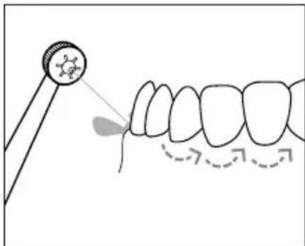
natural_image
Illustration of a dental procedure showing a tooth being pointed at a mirror and then to the teeth with arrows indicating direction (no text or symbols)Fig. 8 Fig. 9
flowchart
graph TD
    A["1: Tooth arrangement"] --> B["2: Formation"]
    B --> C["3: Formation"]
    C --> D["4: Formation"]
Fig. 10
- Cara exterior del maxilar superior
- Cara interior del maxilar superior
- Cara interior del maxilar inferior
- Cara exterior del maxilar inferior
KOMPERNASS HANDELS GMBH
BURGSTRASSE 21
44867 BOCHUM
ALEMANIA
www.kompernass.com
Indholdsfortegnelse
Indledning....164
natural_image
Diagram of a mechanical gear or wheel with a rotating arrow indicating clockwise motion (no text or symbols)
natural_image
Illustration of a dental tool interacting with a tooth, showing the tooth being pointed at its base (no text or symbols present)Fig. 4 Fig. 5
natural_image
Diagram of a mechanical gear or wheel with a rotating arrow indicating rotational motion (no text or symbols)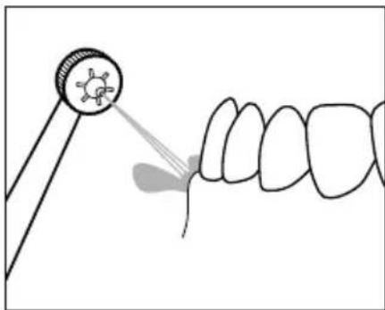
natural_image
Illustration of a dental procedure showing a tooth being injected into a tooth with a magnified inset (no text or symbols)Fig. 6 Fig. 7
natural_image
Illustration of a dental tool projecting a tooth to the upper portion of a tooth (no text or symbols present)
natural_image
Diagram showing a dental tool interacting with teeth, illustrating tooth alignment and tooth movement (no text or symbols)Fig. 8 Fig. 9
KOMPERNASS HANDELS GMBH
BURGSTRASSE 21
44867 BOCHUM
TYSKLAND
www.kompernass.com

KOMPERNASS HANDELS GMBH
BURGSTRASSE 21
44867 BOCHUM
GERMANY
www.kompernass.com
Last Information Update · Stand der Informationen · Version des informations · Stand van de informatie
Stav informaci · Stan informacji · Stav informacií · Estado de las informaciones · Tilstand af information:
12 / 2020 · Ident.-No.: SMD24A1-102020-2
IAN 359279_2007
8=