CT51 - Measuring equipment MULTIMETRIX - Free user manual and instructions
Find the device manual for free CT51 MULTIMETRIX in PDF.

User questions about CT51 MULTIMETRIX
0 question about this device. Answer the ones you know or ask your own.
Ask a new question about this device
Download the instructions for your Measuring equipment in PDF format for free! Find your manual CT51 - MULTIMETRIX and take your electronic device back in hand. On this page are published all the documents necessary for the use of your device. CT51 by MULTIMETRIX.
USER MANUAL CT51 MULTIMETRIX
General Instructions
Introduction
Congratulations on your purchase.
This instrument is part of the MULTIMETRIX range.
Read the following safety instructions before using and refer to the safety messages, to prevent bodily injuries, such as burns and electric shocks.
Symbol

It is essential to follow the indications preceded by the symbol

Safety
Use this device only within the limits of its application.
For Safe Operation...
- Do not use inside electrical cabinets.
- Never work outside of ranges of specified max. voltage.
- Verify the operating condition of the device before use.
- Do not use this device if it is damaged.
- Never use the instrument in damp or dusty environments.
- Do not dismantle the casing.
- Only the battery cover may be opened
- Never use the device with the battery cover open.
Warranty
This equipment is guaranteed to be free from any defect in materials or workmanship, in compliance with the general terms and conditions of sale.
During the warranty period (1 year), the instrument can only be repaired by the manufacturer, who reserves the right to repair the instrument or to exchange all or part of it.
If the equipment is returned to the manufacturer, initial transport costs shall be borne by the customer.
General instructions (continued)
| Warranty (contd.) | The warranty does not apply in the event of:1. improper use of the unit or connection to incompatible equipment2. modification of the equipment without explicit authorization from the manufacturer's technical services3. repair carried out by a person not certified by the manufacturer4. adaptation to a specific application not provided for in the definition of the equipment or in the operating instructions5. an impact, a fall or a flooding. |
| Unpacking and Repacking | All the equipment was verified mechanically and electrically before shipping.However, we recommend performing a quick check to detect any damage that may have occurred during transport.If there is any damage, immediately make the appropriate reservations to the carrier.In you need to return equipment, use the original packaging and enclose written advice of the reasons for the return. |
| Maintenance | |
| Metrological verification | Like all measuring or testing devices, regular instrument verification is necessary.Information and address details available on request:Tel. 02.31.64.51.55 - Fax 02.31.64.51.09 |
| Cleaning | Clean your instrument periodically with a damp cloth soaked with soapy water.Do not use abrasives or solvents. |
| Battery | To open the battery compartment, press on the battery cover at the rear of the casing of the main unit while sliding to the right.Remove the used battery and replace it, making sure that the polarity is correct.Keep the battery away from children. |
| Storage | If you do not use your instrument for a period longer than 60 days, remove the battery and store it separately. |
Description of the instrument
Operating instructions
Precautions for Use
- Do not connect the tester to a powered cable.
- Do not test more than one cable at a time.
Operating instructions
1 - Connect the secondary unit to one end of the cable to be tested and the main unit to the other end.
For a measurement on a wired installation, we recommend detaching the secondary unit from the main unit by sliding the main unit; to do so, push gently as per the indications on the casing.
2 - Press the green button at the centre of the main unit.
3 - Read the result on the test LEDs and interpret them as per the indications given in the paragraph entitled. Test LED on main unit.
Note
On the RJ-45 connectors, the test is performed on 8 LEDs, or on 9 LEDs if the instrument is fitted with a ground connection.
As RJ-11 connectors have 6 wires, the result is read on 6 LEDs.
At link 1394, the result is read on 7 LEDs.
As USB connectors have 4 wires + ground, the result is read on 5 LEDs.
The BNC connector is read on 2 LEDs.
Description of the instrument (continued)
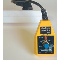
Illustration
Front Panel

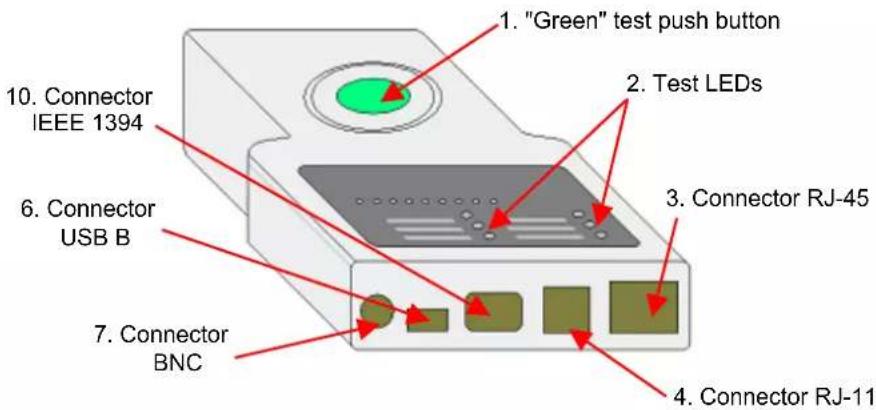
text_image
1. "Green" test push button 2. Test LEDs 3. Connector RJ-45 4. Connector RJ-11 5. Connector USB B 6. Connector BNC 7. Connector
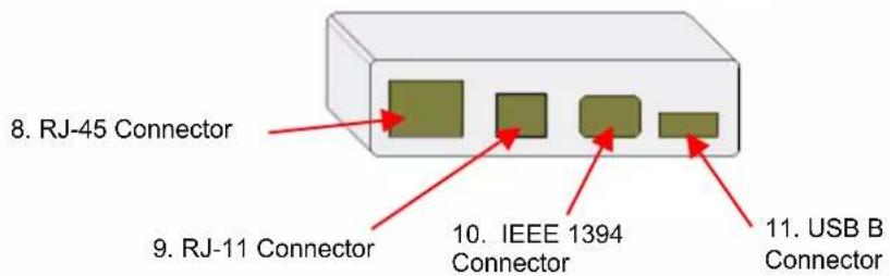
text_image
8. RJ-45 Connector 9. RJ-11 Connector 10. IEEE 1394 Connector 11. USB B ConnectorLegend for main unit
1 Test control push button (green)
2 Test LEDs (see detailed drawing)
3 RJ-45 connector for testing 10BASE-T LAN and INTERNET cables, EIA/TIA-568/568B, AT&T268A, Token Ring and all other cable systems fitted with an RJ-45 connector.
4 RJ-11 connector for testing telephone type cables, PhonNet and any other cable system fitted with RJ-11 connectors.
5 IEEE 1394 connector for testing cables fitted with IEEE connector 1394.
6 USB B connector for testing USB link type cables and any other cable system fitted with USB connectors.
7 BNC Connector for testing 10BASE-2/10BASE-5 ETHERNET terminal connection cables.
Legend for secondary unit
8 Connection for other end of RJ-45 connector
9 Connection for other end of RJ-11 connector
10.
Connection for other end of IEEE 1394 connector
11.
Connection for other end of USB B connector
Test LEDs on main unit
Indication of results
by diodes (LEDs)
Detailed drawing
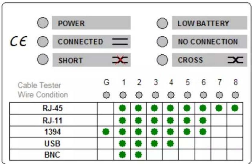
text_image
POWER LOW BATTERY CE CONNECTED = NO CONNECTION SHORT CROSS Cable Tester G 1 2 3 4 5 6 7 8 Wire Condition RJ-45 RJ-11 1394 USB BNCPOWER
CONNECTED
SHORT
LOW BATTERY
NO CONNECTION
CROSS
Test activation
Reading results
Operating indicator
The blue LED goes ON when the connection between the two units is established. In display G 1-8, the LEDs of the conducting conductors go ON and an audio signal is activated.
The red LED goes ON when the connection is made between the main unit and the secondary unit and the cable has a short-circuit. In display G 1-8, the LEDs corresponding to the short-circuiting conductors go ON and two audio signals are activated.
When the yellow LED goes ON, the 9 V battery needs replacing.
If the LED is ON, the secondary unit or the load resistance (BNC) is not connected to the main unit.
The yellow LED goes ON to indicate that the links are crossed over in the connecting cable between the main unit and the secondary unit.
Press the green button at the centre of the tester.
1 Do not connect the tester to a powered cable.
2 Do not test more than one cable at a time.
3 On RJ-45 connectors, the test is performed on 8 LEDs, or on 9 LEDs if the instrument is fitted with a ground connection.
4 As RJ-11 connectors have 6 wires, the result is read on 6 LEDs.
5 With a 1394 link, the result is read on 7 LEDs.
6 As USB connectors have 4 wires, the result is read on 4 LEDs.
7 The BNC connector is read on 2 LEDs.
Test LEDs on main unit (continued)
| Connection diagram and cable pair colours | Pair identification Wire colour codes | T568APin number on connector | |
| Pair 1 | white/blue | 5 | |
| blue | 4 | ||
| Pair 2 | white/orange | 3 | |
| orange | 6 | ||
| Pair 3 | white/green | 1 | |
| green | 2 | ||
| Pair 4 | white/brown | 7 | |
| brown | 8 | ||
| Pair identification Wire colour codes | T568BPin number on connector | ||
| Pair 1 | white/blue | 5 | |
| blue | 4 | ||
| Pair 2 | white/orange | 1 | |
| orange | 2 | ||
| Pair 3 | white/green | 3 | |
| green | 6 | ||
| Pair 4 | white/brown | 7 | |
| brown | 8 | ||
| Protection | Do not use on powered cable. |
| Power supply | One 9 V battery (6 LF22) |
| Safety/Standard | IEC/EN 61010-1 ; Cat. I ; 50 V ; Pol. 2 |
| Maximum range | For RJ11, RJ45 and BNC: approximately 180 m |
General Specifications
| Temperature | |
| Operation | -5°C to 45°C |
| Storage | -10°C to 85°C |
| Mechanical | |
| Dimensions | 200 x 100 x 27 mm |
| Weight | 280 g (cable and battery included) |
Supply
| delivered with the instrument | Adaptors |
| Cables | |
| One 9 V battery | |
| One operating manual |
Allgemeine Hinweise