XA3052 - Measuring equipment MULTIMETRIX - Free user manual and instructions
Find the device manual for free XA3052 MULTIMETRIX in PDF.

User questions about XA3052 MULTIMETRIX
0 question about this device. Answer the ones you know or ask your own.
Ask a new question about this device
Download the instructions for your Measuring equipment in PDF format for free! Find your manual XA3052 - MULTIMETRIX and take your electronic device back in hand. On this page are published all the documents necessary for the use of your device. XA3052 by MULTIMETRIX.
USER MANUAL XA3052 MULTIMETRIX
Dual-Output Power Supply Series and Parallel
Consommation < 550 W
General Instructions
Introduction
Thank you for purchasing this stabilized power supply.
This instrument complies with standard EN 61010-1, 2001, concerning electronic measuring instruments. For your own safety and that of the instrument, you must comply with the instructions in this manual. The manual's contents must not be reproduced by any means whatever without our prior authorization.
Safety
This power supply complies with the EN 61010-1 standard, Class 1, pollution degree 2. It is designed for indoor use at altitudes below 2000 m and at temperatures from 0 °C to 50 °C, with < 80 % relative humidity up to 40 °C.
Power supply outputs
Overvoltage category 100 V CAT I in relation to earth
Maximum output voltage 30.5 V DC in normal mode 61.0 V DC in series mode
Mains power supply
Overvoltage category 300 V CAT II
Power supply voltage 110 V or 230 V ± 10 %; 50-60 Hz
Consumption < 550 W
Definition of installation categories (cf. IEC 664-1)
CATI: CATI circuits are circuits protected by systems limiting transient voltages to a low level.
Example: protected electronic circuits
CAT II: CAT II circuits are the supply circuits of domestic appliances or similar equipment which may carry medium-level transient overvoltages.
Example: power supplies of domestic appliances and portable tools
CAT III: CAT III circuits are power circuits which may carry high transient overvoltages.
Example: power supplies of industrial machinery and equipment
CAT IV: CAT IV circuits are circuits which may carry very high transient voltages.
Example: power feeds
Precautions
Before use
To use this power supply, users must comply with the customary safety rules to ensure that:
- people are protected against the dangers of electric currents,
- the power supply is protected against incorrect operation.
For your safety, only use the lead delivered with the instrument. Before using, make sure each time that it is in perfect condition. It must be connected to the mains network before connecting the outputs.
General Instructions (cont'd)
During use
* Any interruption in the protective conductor inside or outside the instrument and any disconnection of the protective earth terminal may make the instrument hazardous. Intentional interruption is prohibited.
* When this instrument needs to be powered via an external autotransformer to reduce the voltage, make sure that the common terminal is connected to the neutral (earthed pole) of the power supply circuit.
* The plug must only be connected to a socket equipped with an earthing contact. The safety connection must not be interrupted by the use of an extension lead without a protective conductor.
* When the level of the required voltage and current parameters is unknown, start by using the lowest values.
* Before disconnecting the connection leads from the circuit to be tested, make sure that the power supply is switched off. This avoids the generation of make or break extra-currents which may melt the fuse at high current levels.
* The total output voltage must never exceed 60 Vpeak in relation to the earth (common mode).
* The instruments must be set up in a well-ventilated area. Make sure that the ventilation holes are not obstructed.
Symbols on the instrument
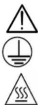
Caution: Refer to the operating manual. Incorrect use may damage the instrument and threaten your safety.
Functional earth
Hot surface
Safety instructions
* Before opening the instrument, you must disconnect it from any source of electric current and from the measurement circuits. You must also make sure that you are not electrostatically charged, as it could lead to damage inside the instrument.
* The fuse must be replaced with a model identical to the original fuse. It is located in a fuse-holder at the rear of the instrument.
* Before opening the power supply, you must disconnect the leads and the mains power cable.
* When the instrument is open, some of the capacitors inside it may retain a dangerous potential even after switching off the power to the instrument.
* In the event of faults or abnormal stresses, declare the instrument "out of order" and prevent it from being used until it has been checked.
* Any adjustment, maintenance or repair of the instrument must be carried out by qualified personnel.
General Instructions (cont'd)
| * A "qualified person" is a person familiar with the installation, its design, its operation and the hazards present. He/she is authorized to start up and shut down the installation and equipment, in compliance with the safety rules. | |
| Safety system | The fuse protects the primary of the supply transformer against network voltage errors.Only use fuses of the following type: T, 4 A / 250 V. |
| Warranty | This equipment is guaranteed against any material or manufacturing defects, in accordance with our General Terms of Sale.During the warranty period, the instrument can only be repaired by the manufacturer, who reserves the right to choose either to repair the equipment or to exchange all or part of the instrument. If the equipment is returned to the manufacturer, shipment to the manufacturer's site shall be payable by the customer. The warranty shall not be applicable in the event of:1. inappropriate use of the instrument or use of the instrument with incompatible equipment2. modification of the equipment without express authorization from the manufacturer's technical department3. maintenance operations carried out by somebody not approved by the manufacturer4. adaptation for a particular application not covered by the equipment specifications or by the operating manual5. shock, fall or flooding. |
| Metrological verification | Like all test and measurement instruments, it must be verified periodically.Information and contact details on request:Tel. (33) 2.31.64.51.55 - Fax (33) 2.31.64.51.09. |
| Cleaning | Disconnect the instrument and then clean it with a cloth slightly moistened with soapy water; leave to dry before using.Never use abrasive products or solvents. |
| Repair | For all repairs before or after expiry of warranty, please return the device to your distributor. |
| Unpacking and repacking | All the equipment has been checked mechanically and electrically before shipment.You are nevertheless advised to make a quick check in order to detect any damage that may have occurred during transport. If there is any damage, contact the carrier immediately to register the customer reservations.If returning the product, use the original packaging and accompany the instrument with a note indicating the reasons for the return. |
Description of the Instrument
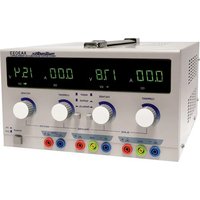
Presentation
This high-accuracy dual-output power supply has been designed to meet the needs of the education sector, laboratories and maintenance departments.
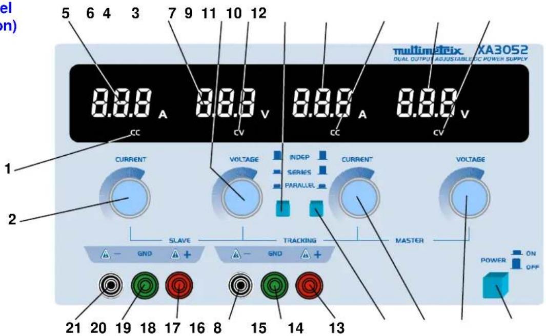
Front panel (illustration)
text_image
5 6 4 3 7 9 11 10 12 5 6 4 3 7 9 11 10 12 multimetreix XA3052 DUAL OUTPUT ADJUSTABLE DC POWER SUPPLY 8.8.8 A 8.8.8 V 8.8.8 A 8.8.8 V CC CV CC CV CURRENT VOLTAGE INDEP CURRENT VOLTAGE SERIES PARALLEL SLAVE TRACKING MASTER GND GND ON POWER OFF 21 20 19 18 17 16 8 15 14 13Control systems
"SLAVE" power supply (left)
- Indicator of constant current (CC) or parallel set-up of the 2 power supplies
- Potentiometer for current adjustment
- Constant voltage (CV) indicator
- Potentiometer for voltage adjustment
- Display of current
- Display of voltage
- "+" output terminal
- Earth terminal
- "-" output terminal
"MASTER" power supply (right)
- Display of current
- Display of voltage
- Constant current (CC) indicator
- Constant voltage (CV) indicator
- Potentiometer for voltage adjustment
- Potentiometer for current adjustment
- "+" output terminal
- Earth terminal
- "-" output terminal
Common controls
- On-Off switch
- & 8. Pushbutton switches for choosing series or parallel
Functional Description
Use as independent outputs
- Set the switches to the "out" position (7) & (8).
Voltage adjustment
- Turn the potentiometers (2) & (15) to the right as far as they will go (max. current).
- Turn the potentiometers (4) & (14) to the left as far as they will go (min. voltage).
- Then switch on the power to the instrument (13).
- Adjust the potentiometers (4) & (14) until the voltage reaches the required value.
• The voltage value is displayed in real time.
• The voltage LEDs (CV) are lit.
• The current LEDs (CC) are off.
Current adjustment
- Switch on the power to the instrument (13).
- Turn the voltage potentiometers (4) & (14) to the right as far as they will go (max. voltage).
- Turn the current potentiometers (2) & (15) to the left as far as they will go (min. current).
- Connect the required load.
- Adjust the potentiometers (2) & (15) until the current reaches the required value.
• The current value displayed is the value of the output current.
• The current LEDs (CC) are lit.
• The voltage LEDs (CV) are off.
Current limitation
When the instrument is used at a constant voltage, the current value can be limited to a required level in the following way:
- Turn the current potentiometers (2) & (15) to the left as far as they will go (min. current).
- Short circuit the "+" and "-" terminals of the power supplies.
- Switch on the power to the instrument.
- Use the potentiometers (2) & (15) to set the required current value.
- Switch off the power to the instrument.
- Remove the short-circuits and connect the loads to the outputs.
- Connect the instrument again and set the voltages to the required values.
The voltage LEDs remain lit until the current reaches the required value.
If it is reached, the voltage LEDs (CV) are switched off and the current LEDs (CC) light up.
Functional Description (cont'd)
| Use of 2 power supplies in series | Set the switch (8) to the "out" position (8) and the other switch (7) to the "in" position.Set the "master" voltage (14); the "slave" voltage is aligned with the "master" voltage.The output voltage between the terminals (16) & (21) is double the voltage displayed for each independent power supply. |
| Before switching to series | Make sure you disconnect the negative terminals of the "master" and "slave" outputs from the earth to prevent short-circuiting of the "slave" output. |
| When the 2 outputs are in seriesExample | The voltage is controlled by the "master" power supply, but the current settings on the two outputs are always independent.Be careful with the position of the current potentiometer (2).If the potentiometer (2) is set as far to the left as it will go or if the "slave" output current exceeds the limit defined, the "slave" output voltage will not be aligned with the "master" voltage.Turn the potentiometer (2) to the right until the 2 outputs are in series. |
| When connected in series | Series connection is provided inside the instrument by switches (7) & (8).If operated in a high-power environment, appropriate leads must be used to link the "-" terminal of the "master" output to the "+" terminal of the "slave" output.If not, the current flowing through the internal series/parallel switches may damage them and affect the instrument's reliability. |
| Use of 2 power supplies in parallel | Set the 2 switches (7) & (8) to the "in" position.Use the potentiometer (14) to adjust the "master" output voltage.The voltages on the 2 outputs remain identical.The "slave" current indicator (1) lights up. |
| When the 2 outputs are in parallel | The current potentiometer (2) of the "slave" output is not active.The current is adjusted using the current potentiometer (15) of the "master" output. The "master" and "slave" current outputs are then controlled by it and are identical.The output current is double the current displayed for each independent. |
| When connected in parallel | Connect the "+" output terminals of the 2 power supplies to one another.Connect the "-" output terminals of the 2 power supplies to one another.3. Connect the load between these outputs using appropriate leads.If the load is connected to one power supply only, a current unbalance may occur between the 2 outputs, damaging the internal series/parallel switches. |
Specifications
| Technical specifications | |
| Number of outputs | 2 |
| Display | Voltage ± 1% + 2 digitsCurrent ± 2% + 2 digits |
| Voltage control | Master output 0 to 30 V DC ± 0.05% + 5 mVSlave output 0 to 30 V DC ± 0.05% + 5 mV |
| Current control | Master output 0 to 5 A ± 0.5% + 5 mASlave output 0 to 5 A ± 0.5% + 5 mA |
| Stability | Ripple < 1 mVrms |
| Input voltage | 110 VAC / 230 VAC ± 10 % 50 - 60 Hz |
| Consumption | < 550 W max. |
| Electromagnetic compatibility | |
| Immunity | EN 55024 |
| Emission | EN 55022 – EN 61000-3-2 – EN 61000-3-3 |
| General specifications | |
| Display | LED - 3 digits – Simultaneous voltage and current |
| Adjustment | Slave and Master outputs: by potentiometer |
| Coupling | Series or parallel |
| Safety | EN 61010-1 (2001) – CAT II 300 V – Pollution 2 |
| Dimensions | 360 x 260 x 155 mm |
| Weight | 11.5 kg |
| Accessories | • Operating manual• 2 fuses: type T, 4 A, 250 V• Mains power cable |