XA3033 - Measuring equipment MULTIMETRIX - Free user manual and instructions
Find the device manual for free XA3033 MULTIMETRIX in PDF.

| Product type | Triple output stabilized power supply |
| Brand | Multimetrix |
| Model | XA3033 |
| Number of outputs | 3 (two variable 0-30 V / 0-3 A and one fixed 5 V / 3 A) |
| Voltage range (variable outputs) | 0 to 30 VDC |
| Current range (variable outputs) | 0 to 3 A |
| Fixed 5 V output | +5 V ± 2.5%, 3 A max |
| Display | LED digital, 3 digits, voltage and current simultaneously |
| Voltage adjustment | By potentiometer on each variable output |
| Current adjustment | By potentiometer on each variable output |
| Coupling modes | Independent, series, parallel |
| Supply voltage | 110 V or 230 V ± 10%, 50-60 Hz |
| Maximum consumption | < 500 W |
| Stability / Ripple | < 1 mVrms (variable outputs), < 5 mVrms (fixed output) |
| Voltage accuracy | ± 1% + 2 digits |
| Current accuracy | ± 2% + 2 digits |
| Dimensions (W x H x D) | 260 x 160 x 340 mm |
| Weight | 10 kg |
| Safety standard | EN 61010-1 (2001), CAT II 300 V, pollution degree 2 |
| Maintenance | Clean with a cloth slightly dampened with soapy water; do not use abrasive products or solvents |
| Supplied accessories | Operating manual, 2 fuses T 3.2 A / 250 V, mains cord |
| Warranty | Warranty against any material defect or manufacturing defect (according to general terms and conditions of sale) |
Frequently Asked Questions - XA3033 MULTIMETRIX
User questions about XA3033 MULTIMETRIX
0 question about this device. Answer the ones you know or ask your own.
Ask a new question about this device
Download the instructions for your Measuring equipment in PDF format for free! Find your manual XA3033 - MULTIMETRIX and take your electronic device back in hand. On this page are published all the documents necessary for the use of your device. XA3033 by MULTIMETRIX.
USER MANUAL XA3033 MULTIMETRIX
Triple Output Adjustable DC Power Supply
Consommation < 500 W
General Instructions
Introduction
You have just acquired a dual power supply. This instrument belongs to the MULTIMETRIX range of products. Thank you for your confidence in our products.
This instrument is compliant with safety standard NF EN 61010-1 (2001), single insulation, concerning electronic measuring instruments.
For optimal service, read this manual carefully and observe the operating precautions.
Non-compliance with the warnings and/or operating instructions might damage the unit and/or its components and might be dangerous for the user.
Safety
This instrument complies with the EN 61010-1 safety standard, class 1. It is designed for indoor use, in a level 2 pollution environment, at an altitude below 2,000 m, at a temperature between 0°C and 50°C with a relative humidity < 80 % up to 40°C.
Power supply outputs
Overvoltage category 100 V CAT I in relation to earth
Max. output voltage 30,5 V DC in normal mode
61,0 DC in series mode V
Mains power supply
Overvoltage category 300 V CAT II
Supply current 110 V or 230 V ± 10 %; 50-60 Hz
Consumption < 500 W
definition of installation categories
(cf. IEC 664-1)
CAT I : CAT I circuits are protected by devices designed to minimize transient overvoltages at a low level.
E.g.: protected electronic circuits
CAT II : CAT II circuits are domestic or similar equipment power supply circuits that can include average value transient overvoltages.
E.g.: power supply to domestic appliances and portable tools.
CAT III : CAT III circuits are circuits for power equipment power supplies which may include high transient overvoltages.
E.g.: machine or industrial apparatus power supply.
CAT IV : CAT IV circuits are circuits that can include very high transient overvoltages.
E.g.: energy inputs
Precautions
Before use
To use this power supply safely, users must comply with the customary safety rules in order to:
- protect them from the dangers of the electric current,
- to protect the power supply against incorrect use.
For your safety, only use the lead delivered with the instrument.
Before using it, always check that it is in perfect condition.
It must be connected to the mains before connecting measurement or control circuits.
General Instructions (cont'd)
| * Any break in the protective conductor, inside or outside the instrument, or disconnection of the protective earth terminal may make the instrument dangerous. Intentional breaking is prohibited.* When this instrument is supplied via an autotransformer in order to reduce the external voltage, make sure that the common terminal is connected to the neutral (earthed pole) of the supply circuit.* The plug should only be inserted into a socket equipped with an earthing contact. The safety connection must not be broken by use of an extension lead without a protective conductor. | |
| When using the instrument | * When the required voltage and current parameter values are not known, start by using the lowest values.* Before disconnecting the connection leads of the circuit being tested, make sure that the power supply is switched off. This prevents the creation of break or closure extra-currents which may melt the fuse at high currents.* Never exceed a total output of 60 V peak in relation to the earth (common mode).* The instrument must be placed in a ventilated room. Take care not to obstruct the ventilation holes. |
| Symbols on the instrument | 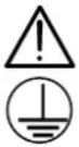 Caution : refer to the manual. Incorrect use may damage the instrument and endanger the user.Functional earth Caution : refer to the manual. Incorrect use may damage the instrument and endanger the user.Functional earth Hot surface Hot surface |
| Instructions | * Before opening the instrument, disconnect if from all sources of electric current and from the measuring circuits; make sure that you are not charged with static electricity, which could irreparably damage the instrument's internal components.* Before opening the power supply to change the fuse, you must disconnect the leads and mains power supply cable. The fuse must be replaced by a model identical to that delivered with the instrument.*When the instrument is open, some of the internal capacitors may conserve a dangerous potential, even once the instrument has been powered down. In the event of faults or abnormal constraints, power down the instrument and do not allow anyone to use it until it has been checked.* Adjustments, maintenance or repair work on the instrument must only be carried out by qualified personnel.*A "qualified person" is someone who is familiar with the installation, the construction, the application and the dangers at hand. This person is authorised to power up and power down the installation and equipment, in compliance with safety regulations. |
General Instructions (cont'd)
Safety features
The fuse protects the primary coil of the power supply transformer against mains voltage errors.
Only use fuse of following type : T, 3.2 A / 250 V.
Guarantee
This equipment is guaranteed against any material or manufacturing defects, in accordance with the general conditions of sale.
During the warranty period (3 years), the instrument can only be repaired by the manufacturer, who reserves the right to repair the instrument or to exchange all or part of it. If the equipment is returned to the manufacturer, the outgoing transport costs are borne by the customer.
The warranty is not applicable in the following cases:
-
improper use of the equipment or use of it in conjunction with incompatible equipment
-
modifications to the equipment without the explicit authorisation of the manufacturer's technical department;
-
work carried out on the instrument by a person not approved by the manufacturer;
-
adaptation for a specific application not included in the definition of the equipment or the user's manual;
-
knocks, falls or flooding.
Metrological verification
Like all measuring or testing devices, a regular check is necessary.
Return your instrument to your distributor for any work to be done within or outside the guarantee.
Cleaning
Disconnect the instrument and then clean it with a cloth slightly moistened with soapy water; leave to dry before using. Never use abrasive products or solvents.
Storage
To guarantee correct operation of the power supply, after a period of storage in extreme environmental conditions, wait for the instrument to return to normal measuring conditions (see environmental specifications). In particular, an abrupt change in the ambient temperature (cold to hot) may lead to condensation inside the instrument and cause short circuits.
Unpacking Repacking
All the equipment has been checked both mechanically and electronically before shipment.
Every precaution has been taken to ensure that you receive the instrument undamaged.
However, it is a good idea to check quickly to detect any damage that may have occurred during transport.
If there is any damage, immediately notify the transporter of the customary reservations.
If you ship this instrument on elsewhere, use preferably the original packaging and indicate the reasons for reshipment as clearly as possible in a note enclosed with the equipment.
Instrument Description
Presentation
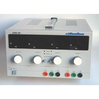
This comprehensive power supply with digital displays is designed to meet the requirements of educational establishments, laboratories and maintenance departments.
Front panel
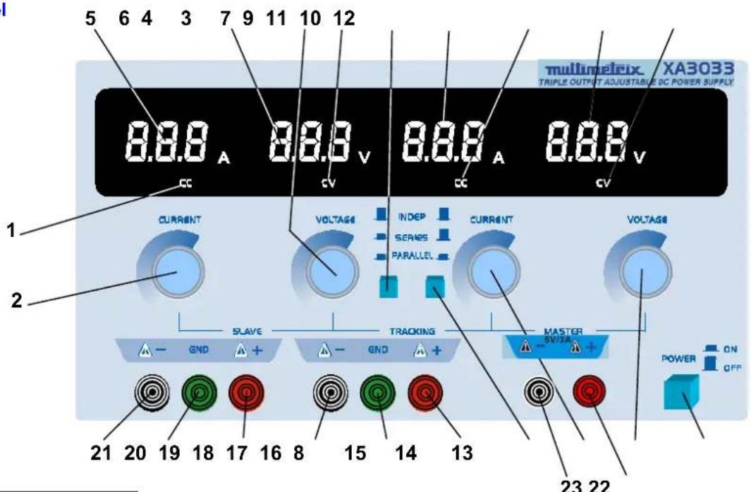
text_image
5 6 4 3 7 9 11 10 12 8.8.8 A 8.8.8 V 8.8.8 A 8.8.8 V CC CV CC CV CURRENT VOLTAGE INDEP CURRENT VOLTAGE INDEP SERIES PARALLEL SLAVE TRACKING MASTER GND GND GND GND GND GND GND GND GND GND GND GND GND GND GND GND GND GND GND GND GND GND GND GND GND GND GND GND GND GND GND GND GND GND GND GND GND GND GND GND GND GND GND GND GND GND GND GND GND GND GND POWER ON OFF 21 20 19 18 17 16 8 15 14 13 23 22Controls
"SLAVE" output (left)
- Slave constant current indicator (CC) or 2-ways parallel state indicator
- Slave constant current adjustment
- Slave constant voltage indicator (CV)
- Slave constant voltage adjustment
- Current display
- Voltage display
- « + » output terminal
- Earth terminal
- « - » output terminal
"MASTER" output (right)
- Current display
- Voltage display
- Constant current indicator (CC)
- Constant voltage indicator (CV)
- Voltage adjustment potentiometer
- Current adjustment potentiometer
- « + » output terminal
- Earth terminal
- « - » output terminal
Common controls
- ON/OFF switch
- & 8. Parallel or series output selecting switch
- « + » output terminal
- « - » output terminal
Functional Description
Independence use of two adjustable outputs
- Set (7) & (8) switch to spring out position.
Voltage adjustment
- Rotate the (2) & (15) potentiometers to right end stop (max. voltage).
- Rotate the (4) & (14) potentiometers to left end stop (min. voltage).
- Turn on power switch (13).
- Adjust the (4) & (14) potentiometers until output voltage reach required voltage value.
- At that time the voltage indicator lights on.
• The voltage indicators (CV) light on. - The current indicators (CC) light off.
Current adjustment
- Switch off the instrument (13).
- Rotate the (4) & (14) voltage potentiometers to right end stop (max. voltage).
- Rotate the (2) & (15) current potentiometers to left end stop (min. current).
- Connect the required load.
- Adjust the (2) & (15) potentiometers until output voltage reach required value.
- The output current value is displayed.
• The current indicators (CC) light on. - The voltage indicators (CV) light off.
Current limitation
Using the instrument in constant voltage, the current value can be limited to a required level, as follows :
- Rotate the (2) & (15) potentiometers to the left end stop (min. current).
- Short-circuit the « + » & « - » outputs of the power supplies.
- Turn on the instrument.
- Bring the current value to the desired level with the (2) & (15) adjustments.
- Turn off the instrument
- Disconnect the short-circuits and load the outputs.
- Turn on the instrument again. Adjust the voltages to the required values.
The « voltage » indciators light on as long as the current value does not reach the required level.
When it is reached, the « voltage » (CV) indicators light off and the « current » (CC) indicators light on.
Functional Description
| Series using the two adjustable outputs | Switch (8) is set to spring out and press in switch (7).Turn the mster voltage adjustment (14); the slave out voltage tracks strictly the master output voltage.The output voltage (16) & (21) can be up to double of independent's maximum voltage. |
| Before the series connecting | It must be examined if the negative terminal of both master and slave output are connected to case grounded terminal, if they are, must be disconnected, otherwise, short-circuit will be caused in the slave output when the two outputs are connected in series. |
| When the two outputs are in seriesExample | The voltage is controlled by master output, but current adjustment of two outputs is still independent..Attention should be paid to the position of the CC adjustment (2).Kob (2) is at the left end stop position or current of slave output excesses current-limiting protection point, at that time, the voltage of slave output will not track the voltage of master.Kob (2) should be rotated to right end stop until the two outputs are in series. |
| Series connection | It is ensured inside the unit by the switches (7) & (8).If there is power output, proper leads corresponding to output power should be used to short connect the negative terminal of master output with positive terminal of slave output reliably.Since it is shorted by a switch inside the unit, current will pass on the shorted switch when there is power output. This will affect the reliability of the unit. |
| Parallel using of the two adjustable outputs | Press in switches (7) & (8).Adjust voltage of the « master » output with the switch (14).The voltage of both outputs remains the same.The « slave » output indicator (1) lights on. |
| when both outputs are in parallel | The current potentiometer (2) of the « slave » output has no effect.The current potentiometer 15) of the « master » output adjusts the current. This potentiometer controls the « master » & « slave » current outputs. Those outputs are identical.The current output is twice as much as the dispayed current for each independent supply. |
| when connecting in parallel | Connect together the « + » output terminals of both supplies.Connect together the « - » output terminals of both supplies.Connect the load between those outputs with the appropriate cables.If the load is connected to one supply only, an imbalance of current between the 2 outputs could occur and damage the internal serial/parallel switches. |
Specifications
| Technical | |
| Outputs | 3 |
| Values | Voltage ± 1 % + 2 digitsCurrent ± 2 % + 2 digits |
| Voltage | « Master » output 0 to 30 VDC ± 0,05 % + 5 mV« Slave » output 0 to 30 VDC ± 0,05 % + 5 mV |
| Current | « Master » output 0 to 3 A ± 0,5% + 5 mA« Slave » output 0 to 3 A ± 0,5% + 5 mA |
| Accuracy | < 1 mVrms |
| 5V constant supply outputs | |
| Voltage | + 5 V ± 2,5 % |
| Current | 3 A max. |
| Stability | < 5 mVrms |
| EMC | |
| Immunity | EN 55024 |
| Emission | EN 55022 – EN 61000-3-2 – EN 61000-3-3 |
| General | |
| Display | Digital - 3 digits - Voltage and Current simultaneous |
| Adjustment | « Slave » and « Master » outputs : with potentiometer |
| Coupling | Serial or parallel |
| Input voltage | 110 VAC / 230 VAC ± 10 % 50 - 60 Hz |
| Consumption | < 500 W max. |
| Safety | EN 61010-1 (2001) – CAT II 300 V – Pollution 2 |
| Dimensions | W x H x D : 260 x 160 x 340 mm |
| Weight | 10 kg |
| Accessories | User' manual2 fuses T, 3.2 A, 250 VMains cord |