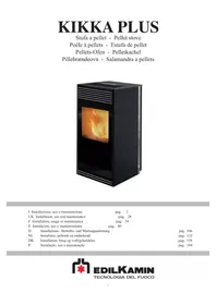
KIKKA PLUS - Oven EDILKAMIN - Free user manual and instructions
Find the device manual for free KIKKA PLUS EDILKAMIN in PDF.


| Product Type | Pellet Stove |
| Brand | Edilkamin |
| Model | KIKKA PLUS |
| Nominal Thermal Power | 8 kW |
| Reduced Thermal Power | 2.5 kW |
| Nominal Efficiency | 91.5% |
| Fuel | Wood pellets (diameter 6 mm) |
| Hopper Capacity | 15 kg |
| Autonomy | 7 to 20 hours |
| Nominal Consumption | 1.8 kg/h |
| Reduced Consumption | 0.6 kg/h |
| Power Supply | 230 V ~ 50 Hz |
| Average Electrical Power Consumption | 120-150 W |
| Ignition Power Consumption | 400 W |
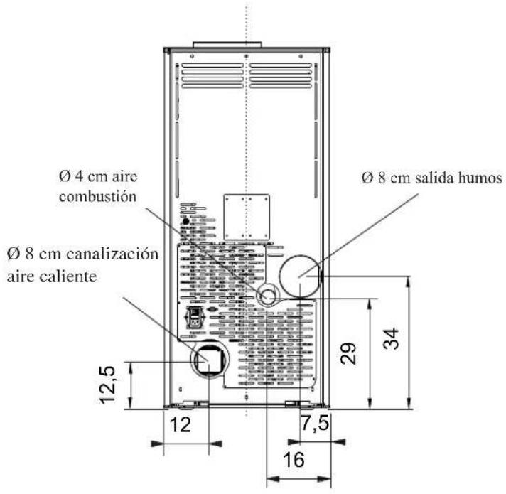
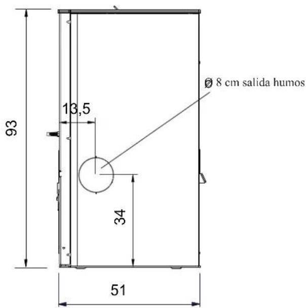
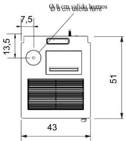
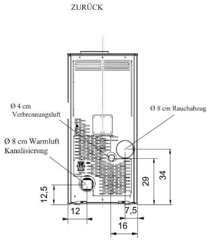
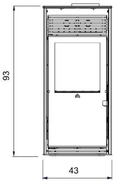
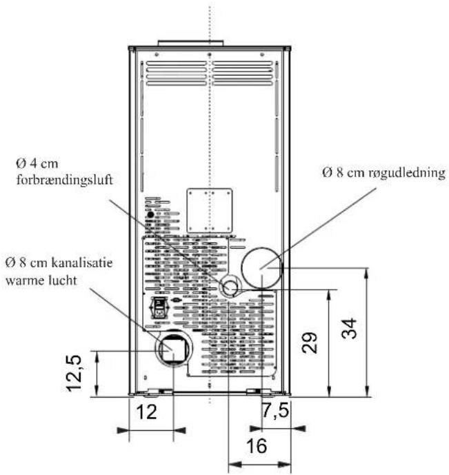
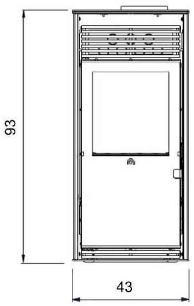
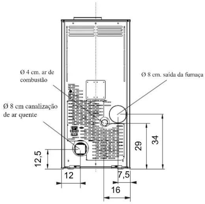
| Flue Pipe Diameter | 80 mm |
| External Air Intake Diameter | 40 mm |
| Weight with Packaging | 146 kg |
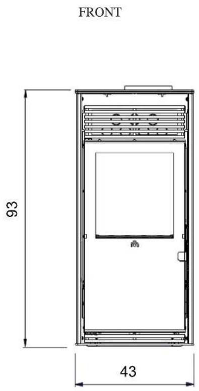
| Indicative Heating Volume | 210 m³ |
| Nominal Draft | 12 Pa |
| Reduced Draft | 5 Pa |
| Nominal Flue Gas Temperature | 133 °C |
| Reduced Flue Gas Temperature | 80 °C |
| CO Emissions (nominal) | 0.013% (at 13% O2) |
| Safety | Flue gas probe, pressure switch, safety thermostat |
| Hot Air Distribution | Possibility of ducting with optional kits |
| Daily Maintenance | Cleaning the burner pot and emptying the ash drawer |
| Weekly Maintenance | Cleaning the upper internal part |
| Monthly Maintenance | Cleaning the flue pipe and connection elbow |
Frequently Asked Questions - KIKKA PLUS EDILKAMIN
User questions about KIKKA PLUS EDILKAMIN
0 question about this device. Answer the ones you know or ask your own.
Ask a new question about this device
Download the instructions for your Oven in PDF format for free! Find your manual KIKKA PLUS - EDILKAMIN and take your electronic device back in hand. On this page are published all the documents necessary for the use of your device. KIKKA PLUS by EDILKAMIN.
USER MANUAL KIKKA PLUS EDILKAMIN
natural_image
Black industrial fueling box with visible flame inside, no text or symbols presentUK Installation, use and maintenance
F Installation, usage et maintenance
natural_image
Close-up of a mechanical component with wires and a paper sheet, no visible text or symbolsFRONTE RETRO
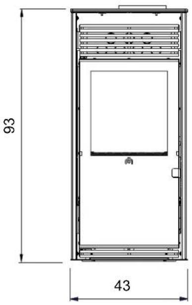
FIANCO
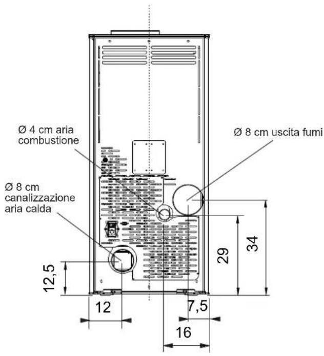
natural_image
Black industrial machine unit with ventilation slots and a label 'fi g. 1' (no visible text on device body)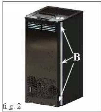
USCITA FUMI
natural_image
Exterior view of a server rack unit with labeled components (A, I, fi g. 3), no readable text or symbols beyond labels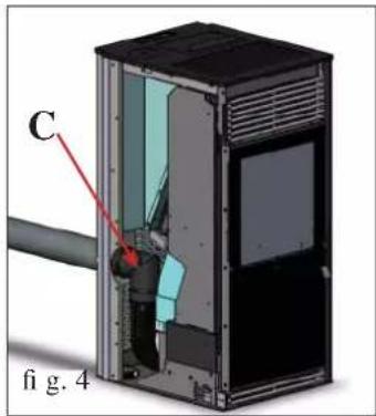
natural_image
Cross-sectional diagram of a device showing internal components and labeled parts (no readable text or symbols)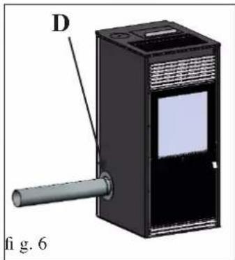
natural_image
3D diagram of a device with labeled component D and pipe, no readable text or symbols presentCOLLEGAMENTO USCITA FUMI LATERALE
natural_image
3D diagram of an open industrial machine with internal components and ventilation ducts (no text or symbols)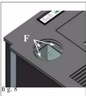
COLLEGAMENTO USCITA FUMI DAL TOP
natural_image
3D diagram of a device with labeled component G, showing internal structure and no readable text or symbols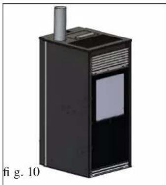
natural_image
3D rendering of a black industrial device with a cylindrical top and label, labeled 'fig. 10' at bottom (no readable text or symbols on the device itself)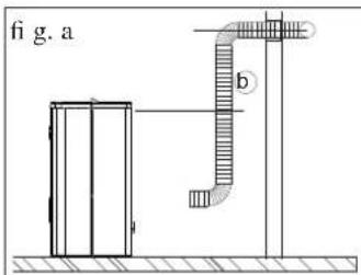
natural_image
Technical line drawing of a mechanical or structural assembly with no visible text or symbols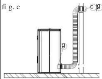
CANALIZZAZIONE ARIA CALDA
KIT 12 BIS (cod. 778160)
PER CANALIZZARE L'ARIA CALDA IN UN LOCALE
REMOTO OLTRE A QUELLO DI INSTALLAZIONE
Composizione:
N.B.:
LA PARTE INIZIALE DEL TUBO FLESSIBILE DEVE ESSERE "DISTESA" COMPLETAMENTE IN MODO DA ELIMINARE IL CORRUGAMENTO; IN TAL MODO IL DIAMETRO INTERNO SI ALLARGHE-RA' SENSIBILMENTE FAVORENDO L'IMBOCCO.
Procedimento:
natural_image
Illustration of a modern air purifier with a lid open, showing internal compartments and ventilation grilles (no text or symbols)fig.1
TELECOMANDO (optional)
natural_image
Technical illustration of a mechanical device with a labeled component (1), showing internal components and housing (no text or symbols beyond label)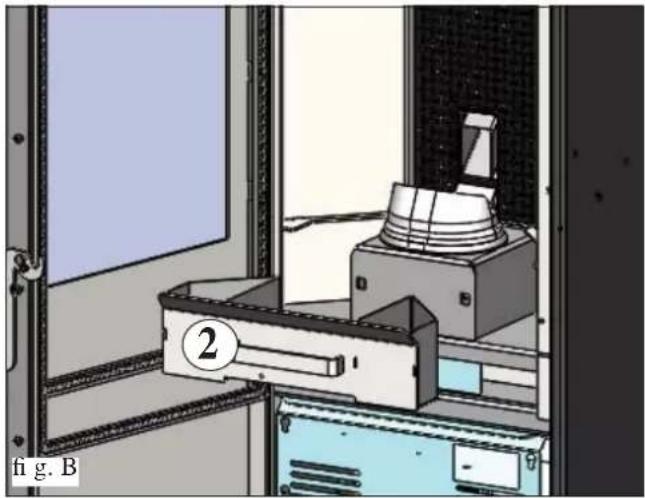
natural_image
Interior view of a laboratory or industrial facility with equipment and a numbered component (no visible text or symbols)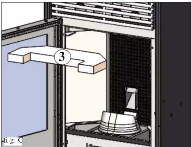
natural_image
Diagram of a laboratory setup with a 3D object labeled '3' and a base, showing no readable text or symbols.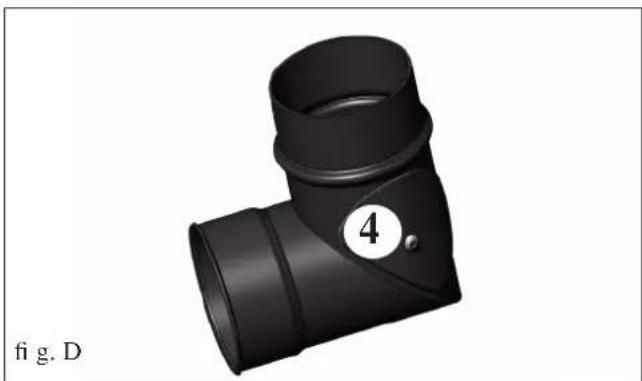
natural_image
3D rendering of a black T-shaped pipe fitting with a numbered circle (4) and label 'fig. D' below (no text or symbols on the object itself)MANUTENZIONE
natural_image
Diagram of a mechanical device with labeled components A and B, showing internal components and housing (no text or symbols beyond labels)fig.1
natural_image
3D rendering of a kitchen appliance with a lid and handle, enclosed in a window frame (no text or symbols visible)fig.2
CONSIGLI PER POSSIBILI INCONVENIENTI
natural_image
Black and white photo of a vacuum cleaner with attached pipe and bulb (no visible text or symbols)Bidone aspiracenere
The undersigned EDILKAMIN S.p.a. with head offi ce headquarters at Via Vincenzo Monti 47 - 20123 Milan - Italy - VAT IT00192220192
Declares under its own responsibility as follows: The pellet stove illustrated below conforms to Regulation EU 305/2011 (CPR) and to the harmonised European Standard EN 14785:2006
WOOD PELLET STOVES, trademark EDILKAMIN, called KIKKA PLUS
Year of manufacture: Ref. Data nameplate Declaration of performance (DoP - EK 114): Ref. data tag plate
In addition, it is hereby declared that: the wood pellet stove KIKKA PLUS is in compliance with the requirements of the European directives: 2006/95/EC - Low voltage directive 2004/108/EC - Electromagnetic compatibility directive
EDILKAMIN S.p.a. will decline all responsibility of malfunctioning or damage to the equipment in case of unauthorized substitution, assembly or modifications of any sort on the said equipment on the part of non-EDILKAMIN personnel.
Dear Sir/Madam
Congratulations and thank you for choosing our product.
Please read this document carefully before you use this product in order to obtain the best performance in complete safety.
For further details or assistance, please contact the DEALER where you purchased the product or visit our website www.edilkamin.com and click on DEALERS.
NOTE
- After having unpacked the stove, ensure that its contents are complete and intact (rosette, multiple smoke output kit, guarantee booklet, glove, CD/technical data sheet, spatula, dehumidifying salt).
In case of anomalies please contact the dealer where you purchased the product immediately.
You will need to present a copy of the warranty booklet and valid proof of purchase.
- Commissioning/ testing
This must be carried out by an EDILKAMIN authorised Technical Assistance Centre (TAC) to guarantee proper operation.
Commissioning, as specified in standard UNI 10683 consists in a series inspections to be performed with the stove installed in order to ascertain the correct operation of the system and its compliance to applicable regulations
Details of your nearest Service Centre can be obtained from your dealer, from our website at www.edilkamin.com or by ringing the helpline.
- Incorrect installation, incorrect maintenance, or improper use of the product, shall relieve the manufacturer from responsibility for any damage resulting from the use of this product.
- series number, necessary for identification of the stove, is indicated:
- on the top of the package
- in the warranty booklet found inside the fi rebox
- on the ID plate affi xed to the back side of the unit;
This documentation must be saved for identification together with the valid proof-of-purchase receipt. The data contained therein must be reported when requesting information and made available should servicing be required;
- All images are for illustration purposes only; actual products may vary.
SAFETY INFORMATION
- The appliance is not designed to be used by people, including children, with reduced physical, sensorial or mental abilities. Children must be supervised to ensure they do not play with the appliance.
- The main risks that may derive from using the stove pertain to non-compliance with installation instructions, direct contact with live electrical parts (internal), contact with the fire or hot parts (glass, pipes, hot air output), when extraneous substances or non-recommended fuel are introduced, or due to incorrect maintenance or by repeatedly pressing the ignition button without having emptied the crucible.
- Only use certified, high quality, 6 mm diameter wooden pellets for fuel.
- Should components fail, the stoves are equipped with safety devices that guarantee automatic shutdown. These are activated without any intervention required.
- In order to function correctly, the stove must be installed in accordance with the instructions given herein and the door must not be opened during operation: combustion is fully automatic and requires no intervention.
- Under no circumstances should any foreign substances be entered into the hearth or hopper.
- Do not use fl ammable products to clean the smoke channel (the fl ue section connecting the stove smoke outlet to the chimney fl ue).
- The hearth and hopper parts must only be cleaned when COLD.
- The glass can be cleaned when COLD with a suitable product (e.g. GlassKamin Edilkamin) and a cloth.
-
Avoid opening the door of the combustion chamber when the stove is hot; wait until it has cooled down naturally.
-
The stove must not function if the door is open, if the glass is broken or if the pellet-loading port is open.
- It must not be used as a step ladder or a base on which to rest any object.
- Do not lay laundry directly on the stove to dry. Any clothes horse or similar must be placed at a safe distance from the stove (danger of fire).
- Make sure the stove is installed and ignited the first time by Edilkamin-qualified CAT personnel (technical assistance centre) in accordance with the instructions provided here within; this is an essential requirement for the validation of the guarantee.
- When the stove is in operation, the exhaust pipes and door become very hot (do not touch without wearing the thermal glove).
- Do not place anything, which is not heat resistant near the stove.
- NEVER use liquid fuel to ignite the stove or rekindle the embers.
- Do not obstruct the ventilation apertures in the room where the stove is installed, nor the air inlets of the stove itself.
- Do not wet the stove and do not go near electrical parts with wet hands.
- Do not use reducers on the smoke exhaust pipes.
- The stove must be installed in a room that is suitable for fi re prevention and equipped with all that is required (power and air supply and outlets) for the stove to function correctly and safely.
- SHOULD IGNITION FAIL, DO NOT RE-IGNITE UNTIL YOU HAVE EMPTIED THE COMBUSTION CHAMBER.
GENERAL INFORMATION
The stove produces hot air using wood pellets as fuel, with electronically controlled combustion.
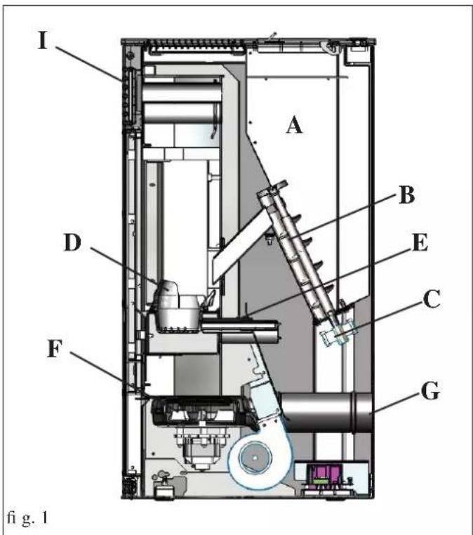
Hereunder is the explanation of its functions (the letters refer to figure 1).
The fuel (pellets) is taken from the hopper (A) and, using a screw (B) operated by a gear motor (C), is sent to the crucible (D).
The pellets are lit by hot air produced by an electrical element (E) sucked into the crucible through a smoke extractor fan (F).
The smoke produced by combustion is extracted from the combustion chamber by the same fan (F) and expelled from the vent (G) which can be connected to the back, the left side or the top of the stove (see page 38).
The KIKKA PLUS stove is designed to distribute hot hair to the room where it is installed and even to another room.
In order to channel hot air to another room, it is necessary to use the following optional kits (more details on page 39-40).
- KIT 12 for distributing hot air to an adjacent room
- KIT 12 BIS for distributing hot air to a remote room
The heart, coated in steel/cast iron, is frontally closed by a ceramic glass door.
The quantity of fuel, the extraction of the smoke and the input of air for combustion are regulated by a motherboard equipped with software, to obtain a high combustion yield and low emissions.
The main phases can be managed by display or remote control supplied as optional.
The stove is equipped with a serial port to connect an optional cable (code 640560) to be connected to devices that allow remote ignition (e.g. remote telephone, local thermostat, ect.)
GENERAL INFORMATION
• ELECTRONIC EQUIPMENT

SAFETY DEVICES
• SMOKE SENSOR:
Placed at the smoke outlet to detect the temperature.
Turns the stove on and off and controls its operation based on defined parameters.
• PRESSURE SWITCH
Positioned in the fume-aspiration area, it is triggered in the case of a depression in the fumes circuit (e.g. obstructed flue) and interrupts the movement of the pellets.
It blocks pellet loading causing the stove to go out.
• SAFETY THERMOSTAT:
Trips when the temperature inside the stove is too high. It stops pellet loading, causing the stove to go out.
SERIAL PORT
The Dealer can install an optional on the AUX outlet for controlling the process of switching on and off (e.g. telephone remote, local thermostat), located at the rear of the stove. This can be connected via special optional trestle (code 640560).
BACKUP BATTERY
A backup battery is found on the control board (CR 1632 battery). Its malfunction is indicated with the following messages (not considered a defect but due to normal wear-and-tear): "Battery check". For more detailed information, please contact the DEALER who performed the first ignition.
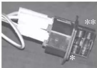
FUSE \*
Two fuses are inserted in the socket with switch, located on the back of the stove, one of which operational * and the other is held in reserve **.
natural_image
Close-up of a mechanical component with wires and a paper sheet, no visible text or symbolsGENERAL INFORMATION
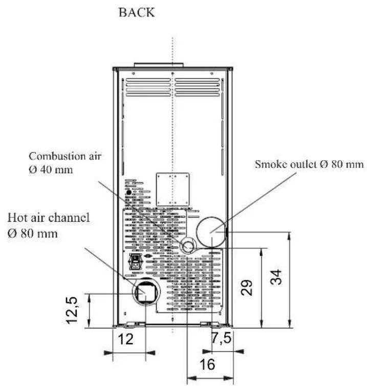
SIDE SYSTEM
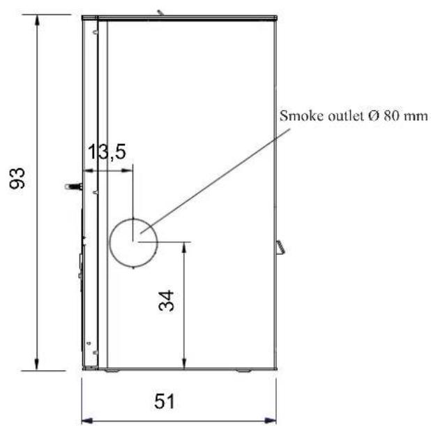
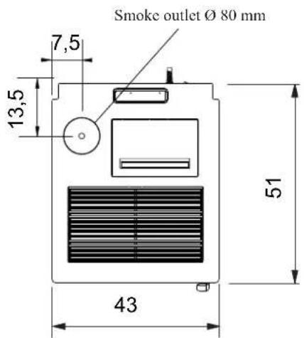
GENERAL INFORMATION
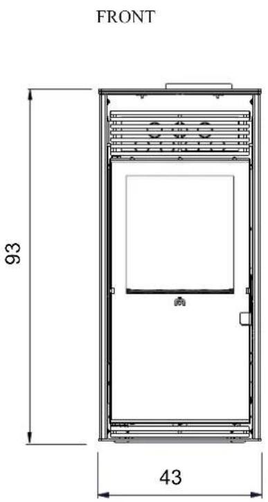
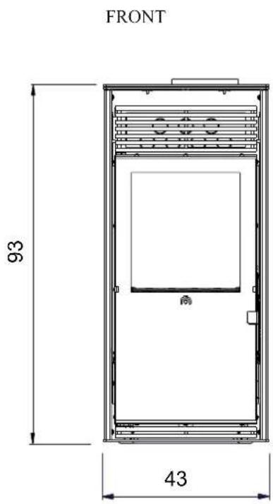
| THERMO TECHNICAL CHARACTERISTICS according to EN 14785 (for other values, see DoP on page 35) | |||
| Nominal power Reduced power | |||
| Thermal power output 8 2,5 kW | |||
| Yield / Effi ciency 91,5 92,5 % | |||
| Emissions CO 13% O2 0,013 0,051 % | |||
| Fume temperature | 133 | 80 | °C |
| Fuel consumption | 1,8 | 0,6 | kg/h |
| Hopper capacity | 15 | kg | |
| Draught | 12 - 5 | 10 - 3 | Pa |
| Autonomy | 7 | 20 | hours |
| Heatable volume * | 210 | m^3 | |
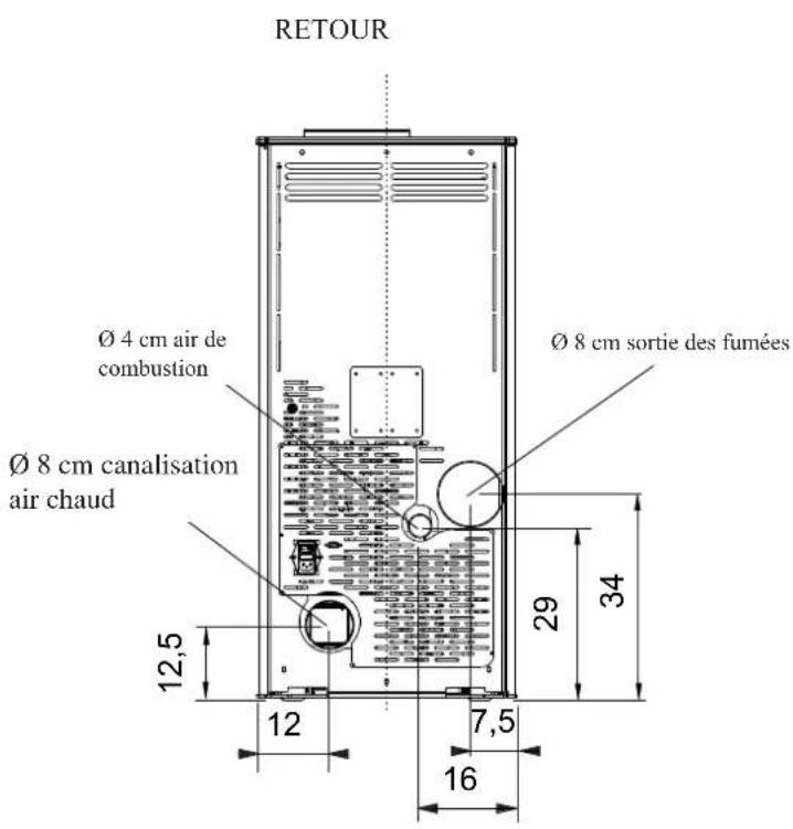
| Smoke outlet pipe diameter (male) | 80 | mm | |
| Air intake pipe diameter (male) | 40 | mm | |
| Weight including packaging | 146 | kg | |
| TECHNICAL DATA FOR SIZING THE FLUE which must, in any case, comply with the guidelines of this sheet and the installation rules for each product | |||
| Nominal power Reduced power | |||
| Thermal power output 8 2,5 kW | |||
| Temperature of fumes on exit from the discharge pipe | 160 | 96 | °C |
| Minimum draught | 0 - 5 | Pa | |
| Fume flow capacity | 5,7 | 3,2 | g/s |
* The heatable room dimensions are calculated on the basis of home insulation in compliance with Italian law 10/91, and subsequent changes together with an expected heat output of 33Kcal / m^3 per hour.
| ELECTRICAL CHARACTERISTICS | |
| Power supply | 230 Vac +/- 10% 50 Hz |
| Average power consumption | 120 - 150 W |
| Power consumption during ignition | 400 W |
| Protection on electronic circuit board | Fusibile 2AT, 250 Vac 5x20 |
N.B.
1) keep in mind that external devices can cause interference to the operation of the circuit board.
2) warning: activity on live components, maintenance and/or checks must be carried out by qualified personnel.
(before carrying out any maintenance, disconnect the appliance from the mains electricity)
3) In case of problems with the electrical grid, consult an electrician to evaluate the installation of a sine-wave UPS of at least 800 Va. Power variations greater than 10% can cause problems for the product.
The above data are indicative and are those resulting during certification on the part of the notified body.
EDILKAMIN s.p.a. reserves the right to change the products at its discretion without notice.
GENERAL INFORMATION

EDILKAMIN
TECNOLOGIA DEL FUOCO
EdRamin S.p.A.
20020 Leinale (M) - Via Maesagni. T
Tel. +39 02 937621
Fax: +39 02 83352 400310
PAS-23 de 10/16 de 40
(https://doi.org/10.103.com)
www.lookam.com
Capitise € 4.100.000 int. vers.
Seche invales:
2012/11/2007 Via Vinozero Monti 47
2012.3.1940: Via vendato leoni
Reg. Imp. di Nett
REA # 878860
Cod. Fiscale e Partita IVA 00192220192
Declaration of performance
According to Regulation (EU) No. 305/2011
N. EK114
- Unique Identification code of the product-type ZARA PLUS
| 2. Model (Article 11-4) KIKKA PLUS | |
| 3. Intended uses of the product in accordante with the applicable harmonized technical specification | Appliance for domestic heating, fuelled with wood pellet, without hot water production |
| 4. Name or trade mark of the manufacturer (Article 11-5) | EDILKAMIN S.p.A.Via Mascagni, 7 - 20020 Lainate [MI] Italy tel. +39 02 937621 - mail@edilkamin.com |
| 5. Name and address of the agent (Article 12-2) | |
| 6. Assessment and verification system for constancy of performance (Annex 5) | System 3 and System 4 |
| 7. Laboratory notified Test report number (based on System 3) | IMQprimacontrol -NB1881CPR-13-019 51 |
- Declared performance
| Harmonized technical specification EN 14785-2006 | ||
| Essential characteristics Performance | ||
| Reaction to fire A1 | ||
| Distance to combustible materials(minimum distance in mm) | ||
| Risk of burning fuel falling out Pass | ||
| Emission of combustion productsCO (ref. at 13% O2)NOx (ref. at 13% O2)OGC (ref. at 13% O2)Particulate matter (ref. at 13% O2) | Rated fuel load162 mg/Nm3 - 0,013%141 mg/Nm37 mg/Nm310 mg/Nm3 | Reduced fuel load640 mg/Nm3 - 0,051%98 mg/Nm39 mg/Nm34 mg/Nm3 |
| Surface temperature Pass | ||
| Electrical safety Pass | ||
| Cleanability Pass | ||
| Maximum operating pressure bar | ||
| Mechanical resistance (to carry a chimneyflue) | NPD (No performance declared) | |
| Thermal outputNominal heat outputNominal space heating outputNominal boiler output (to water) | Rated fuel load8 kW8 kW- kW | Reduced fuel load7,5 kW2,5 kW- kW |
| Energy efficiency 91,5 % 92,5 % | ||
| Flue gas temperature T [133°C] T[80°C] | ||
- The performance of the product identified in points 1 and 2 is in conformity with the declared performance in point 8
This declaration of performance is issued under the sole responsibility of the manufacturer identified in point 4.
Signed for and on behalf of Edilkamin S.o.A. by:
Chief Executive officer
Lainate, 22/09/2014 Dott. Stefano BORSATTI
• CERTIFICATIONS AND BENEFITS \*
* Given their variability over time in the various countries, check from time to time.
This text is valid for the year this sheet was prepared (see edition details on the last page).
ITALY: allowed in Lombardy pursuant to DGR No. 1118-2013 allowed in the Marche region pursuant to Regional Law No. 3 of 2012 admitted to the Conto Termico (renewable heating incentive) with thermal coefficient 1,5; see the website www.edilkamin.com for how much you can save in the various areas admitted to a 50% deduction; 65% (check the conditions of external accessibility to the product)
FRANCE: enrolled in Flamme Verte
GERMANY: omplies with Bimsch
SWITZERLAND: complies with VKF
INSTALLATION
GENERAL NOTES
In Italy it is necessary to refer to the standard declaration of conformity conforming to Ministerial Decree 37/2008 (pursuant to Law 46/1990) and standards UNI 10683 and UNI 10412-2.
In the case of installation in a multiple-tenancy building, contact the building manager before installation.
VERIFY COMPATIBILITY WITH OTHER DEVICES
In Italy the stove MUST NOT be installed in the same space as type B gas heating equipment (e.g. gas boilers, stoves, and equipment served by an extraction hood - ref. UNI 10683 and 7129).
In general, the stove could create low pressure in the room, affecting the operation of such appliances or being affected by them.
VERIFYTHE POWER SUPPLY CONNECTION (the plug must be accessible)
The stove is supplied with a power cable that is to be connected to a 230V 50 Hz socket, preferably fi tted with a magnetothermic switch. Voltage variations exceeding 10% can damage the stove (unless already installed, an appropriate differential switch must be fi tted). The electrical system must comply with the law; particularly verify the effi ciency of the earthing system. The power line must have a suitable cross-section for the stove's power. An inadequate earthing system can cause anomalies for which Edilkamin cannot be held liable.
In case of problems with the electrical grid, consult an electrician to evaluate the installation of a sine-wave UPS of at least 800 VA.
AIR INTAKE (mandatory to do)
The room where the stove is located must have an air intake with cross section of at least 80cm^2 to ensure replenishment of the air consumed by combustion.
Alternatively, the stove air may be taken directly from outside through a 4 cm steel extension of the pipe.
In this case, there may be condensation problems and it is necessary to protect the air intake with a grille, which must have a freesection of at least 12 cm^2 .
The pipe fitted to the outer side of the product should have a maximum length of 1 meter and be free of bents.
It must end with section at 90^ facing downwards or be fitted with a wind guard. In any case all the way air intake duct must be a free section of at least 12 cm^2 .
The external terminal of the air inlet channel must be protected with an anti-insect netting that does not reduce the 12 cm^2 through passage.
POSITIONING AND DISTANCES FOR FIRE SAFETY
The stove must be installed in compliance with the following safety conditions:
- minimum distance from fl ammable materials around the sides and back of the stove: 20 cm
- fl ammable materials must not be placed less than 80 cm from the front of the stove.
If it is not possible to comply with the above-mentioned distances, technical and construction-related provisions must be taken to prevent fire hazards.
If connected to wooden walls or other flammable materials, the smoke exhaust pipe must be insulated.
INSTALLATION
SMOKE OUTLET
The stove must have its own smoke outlet (the smoke cannot be discharged into a smoke flue used by other devices).
The smoke is discharged through the 8 cm diameter outlet at the back, left side or top of the stove.
The smoke outlet must be connected to outside by means of suitable steel pipes EN 1856 certifi ed.
The pipe must be hermetically sealed.
The material used to seal and if necessary insulate the pipes, must be resistant to high temperatures (high temperature silicone or mastic).
The only horizontal section allowed may be up to 2 m long up to three 90° bends (in relation to the vertical).
A vertical section of at least 1.5 m and an anti-wind terminal is necessary (if the discharge outlet is not in a chimney fluc reference UNI 10683).
The vertical duct can be internal or external.
If the smoke channel is outside, it must be appropriately insulated.
If the smoke channel is fitted inside a chimney flue, the latter must be suitable for solid fuel.
If it is wider than 150 mm in diameter it must be improved by entering a pipe that has a suitable cross-section and is made of suitable material (e.g. 80 mm diameter steel).
All sections of the smoke duct must be accessible for inspection.
The chimney pots and smoke ducts connected to the solid fuel appliances must be cleaned once a year (verify whether a specific legislation exists in your country).
Failure to regularly inspect and clean the stove increases the probability of a fi re occurring in the chimney pot. In that case, proceed as follows:
Do not use water to extinguish the fire; Empty the pellet hopper; Contact specialist personnel before reigniting the stove.
The stove is designed to work under any weather conditions.
In case of particular conditions, such as strong wind, the safety system may be activated, which results in the stove being extinguished.
If this happens, do not operate the stove with the safety devices disabled.
If the problem persists, contact our Technical Service Department.
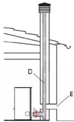
TYPICAL EXAMPLES
Fig. 1
Fig.
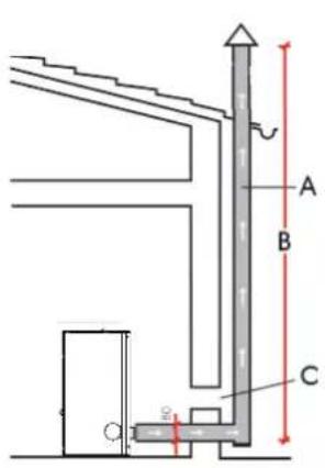
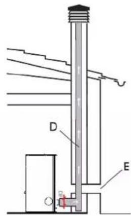
A: flue in insulated steel compliant with EN 1856
B: minimum height of 1.5 m and in any case above the height of the roof gutter
C-E: air intake from inside room (minimum internal section: 80 cm²)
D: steel flue, inside existing brick-built chimney.
CHIMNEY POT
The main characteristics are:
- an internal cross-section at the base, which is the same as that of the chimney fl ue
- an outlet cross-section which is no smaller than twice that of the chimney fl ue
- its position must be high enough to catch the wind and avoid downdraft areas in turbulent wind, it must be high enough to catch the wind and avoid downdraft areas in turbulent wind.
INSTALLATION
natural_image
Black industrial machine unit with ventilation slots and a label 'fi g. 1' (no visible text or symbols on the device itself)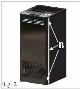
SMOKE OUTPUT
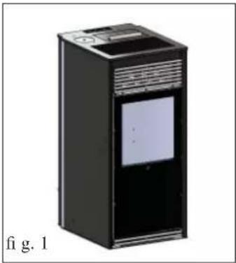
KIKKA PLUS is designed for the connection of the fl ue at the top, back or side left of the stove.
The stove is delivered ready for the output of the flue from the back (fi g. 1).
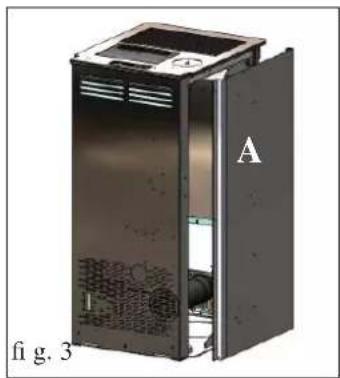
FOR THE CONNECTION OF THE SMOKE OUTPUT TO THE CHIMNEY, WHETHER FROM THE BACK, SIDE OR TOP, IT IS NECESSARY TO REMOVE THE CORRESPONDING METAL SIDE LEFT.
natural_image
Interior view of a server rack unit labeled A, showing internal components and ventilation duct (no text or symbols beyond label)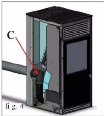
To connect:
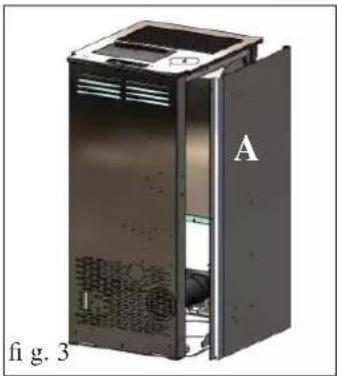
- Remove the left metal side by the 3 screws on the back (B - fi g.2)
At this point, choose the necessary fl ue connection.
REAR SMOKE OUTPUT CONNECTION
Fit the elbow joint to the smoke extractor unit vent (C- fi g. 4) with the band provided.
Connect the side smoke output pipe (not provided) to the aforementioned elbow joint.
In this case it is sufficient to make the smoke output pipe (not provided) pass through the hole in the lower part of the sheet metal back.
natural_image
Cross-sectional diagram of a device showing internal components and labeled parts (no readable text or symbols)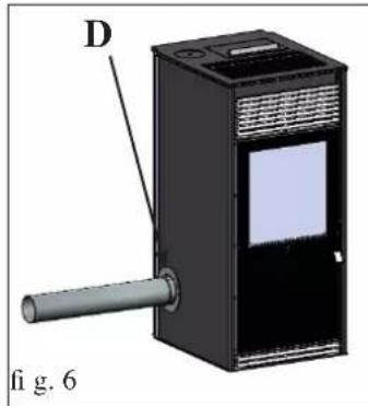
natural_image
3D diagram of a device with labeled component D and pipe, no readable text or symbols presentSIDE SMOKE OUTPUT CONNECTION
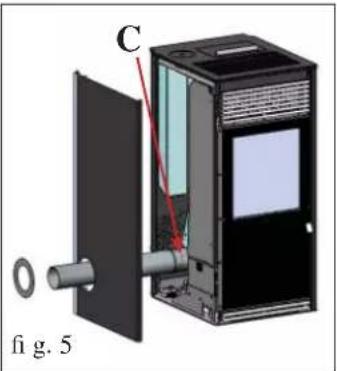
Fit the elbow joint to the smoke extractor unit vent (C- fi g. 5) with the band provided.
Connect the side smoke output pipe (not provided) to the aforementioned elbow joint.
Remove the pre-cut diaphragm from the sheet metal side to allow the smoke output pipe (not provided) to pass through (fi g. 5).
Complete the operation by applying the closure rosette provided (D - fi g. 6) using the screws provided, after replacing the metal side.
natural_image
3D cutaway diagram of a device showing internal components and casing (no text or symbols)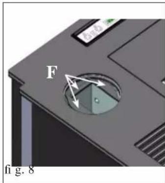
N.B. The rosette and the metal side must be fitted after the flue has been definitively fixed.
TOP SMOKE OUTPUT CONNECTION
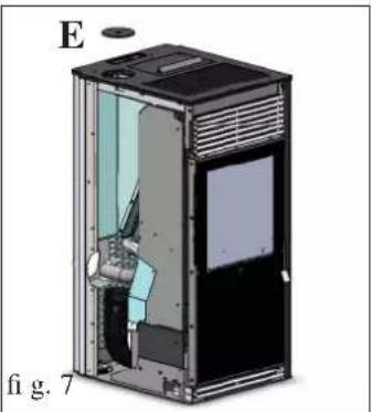
Remove the metal cover (E - fi g. 7) and eliminate the three tabs (F - Fig. 8) with pincers in order to allow the passage of fume discharge pipe.
natural_image
3D diagram of a device casing with labeled component G, no readable text or symbols present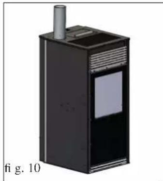
natural_image
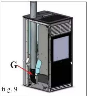
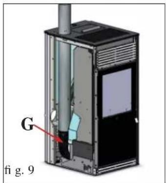
3D rendering of a black industrial device with a cylindrical top and label, labeled 'fi g. 10' (no other text or symbols)Connect the rear smoke output pipe (not provided) to the smoke extractor unit vent (G - fi g. 9) with the band provided.
AFTER COMPLETING THE CONNECTION OF THE SMOKE OUTPUT PIPE TO THE FLUE, REPLACE THE METAL SIDE.
HOT-AIR DUCTWORK
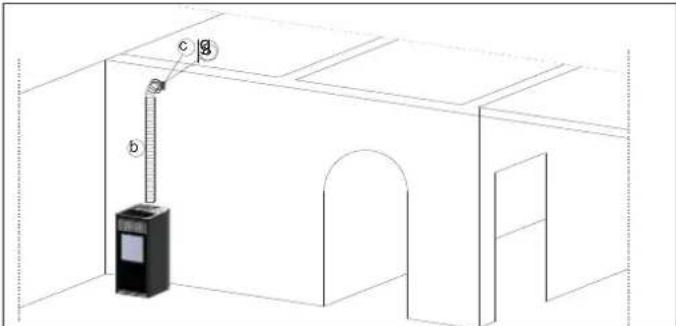
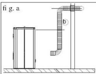
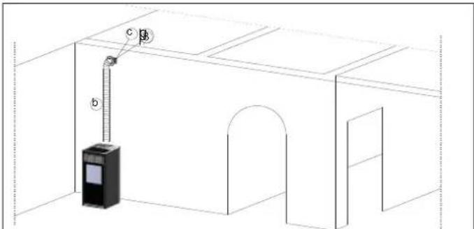
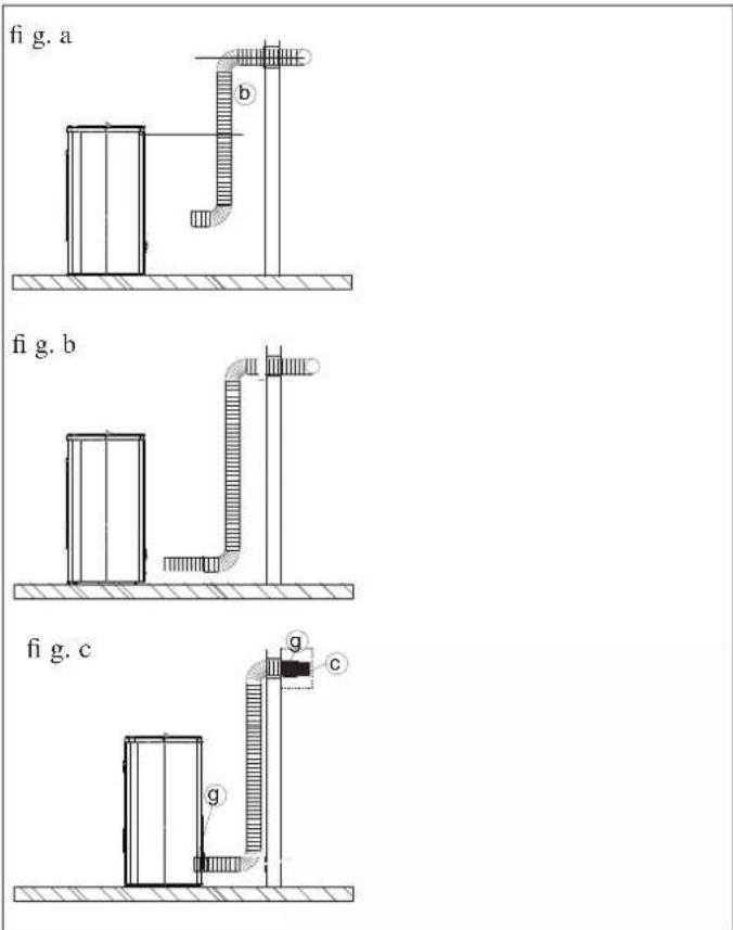
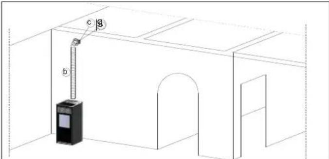
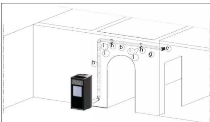
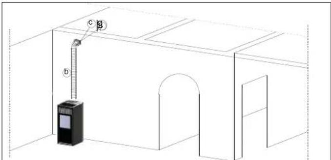
KIT 12 (code 778150) (optional) TO CHANNEL HOT AIR INTO AN ADJACENT ROOM IN ADDITION TO THAT OF INSTALLATION
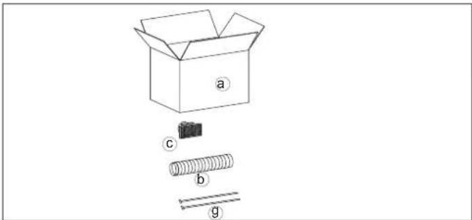
Includes:
| a | Box n° 1 | |
| b | ∅ 8 pipe n° 1 | |
| c | Smoke outlet end-piece n° 1 | |
| g | Pipe blocking clamp n° 2 |
NOTE: THE FIRST PART OF THE FLEXIBLE PIPE MUST BE COMPLETELY "RELAXED" IN SUCH AWAY TO ELIMINATE CORRUGATION. IN THIS WAY, THE INTERNAL DIAMETER WILL BE SLIGHTLY ENLARGED TO FAVOUR ENTRANCE.
Procedure:
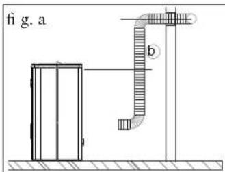
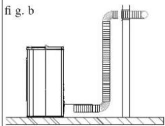
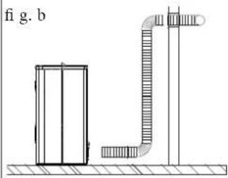
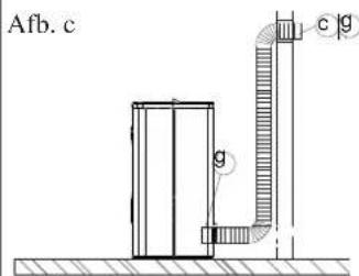
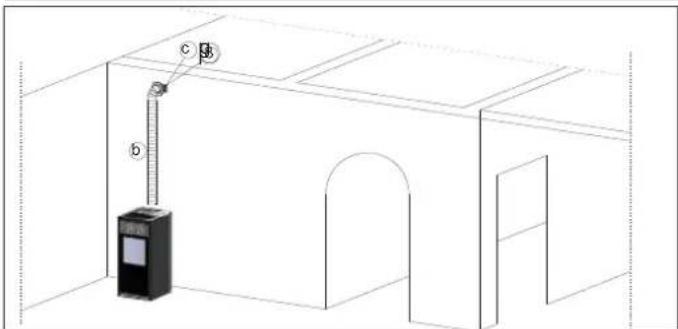
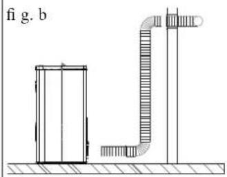
- Defi ne the position of the stove with respect to the walling (fi g. a).
- Place the stove in its definite position.
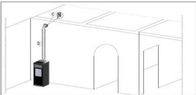
- Extend the aluminium pipe (b) for hot air channelling, without connecting the stove outlet.
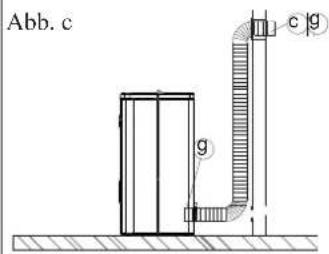
- Fit the alluminium pipe to the hot air outlet on the back of the stove (fi g.C) and fasten it by its blocking clamp (g)
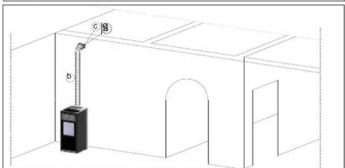
- Install the terminal outlet (c) to the end of the alluminum pipe by its blocking clamp (g) (fi g. c) in the room to heat
natural_image
Technical line drawing of a mechanical or electrical component with no visible text or symbols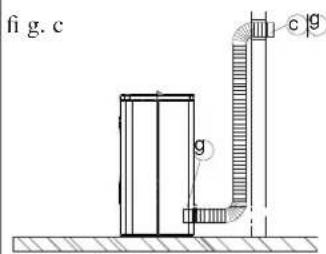
natural_image
Isometric line drawing of a room with a hanging trash bin and labeled points (b, c), no text or symbols present.HOT-AIR DUCTWORK
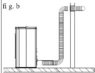
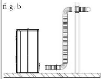
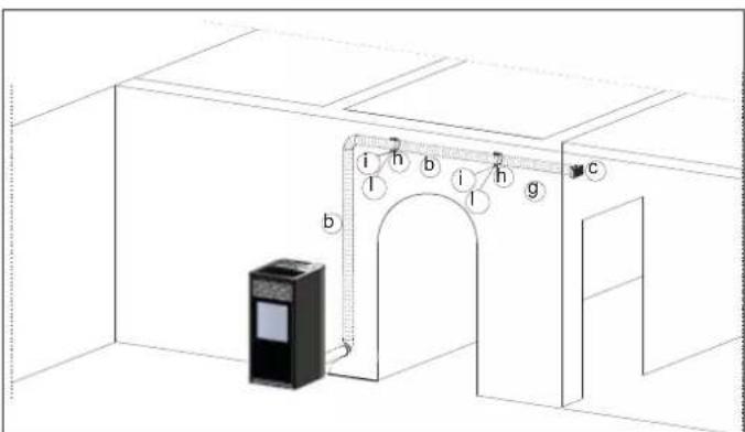
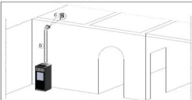
KIT 12 BIS (code 778160) (optional) TO CHANNEL HOT AIR INTO A REMOTE ROOM IN ADDITION TO THAT OF INSTALLATION
Includes:
NOTE: THE FIRST PART OF THE FLEXIBLE PIPE MUST BE COMPLETELY "RELAXED" IN SUCH AWAY TO ELIMINATE CORRUGATION. IN THIS WAY, THE INTERNAL DIAMETER WILL BE SLIGHTLY ENLARGED TO FAVOUR ENTRANCE.
Procedure:
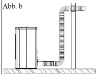
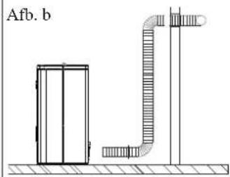
- Defi ne the position of the stove with respect to the walling (fi g. a).
- Place the stove in its definite position.
- Extend the aluminium pipe (b) for hot air channelling, without connecting the stove outlet.
- Fit the alluminium pipe to the hot air outlet on the back of the stove (fi g.C) and fasten it by its blocking clamp (g)
- Install the hot air outlet(c) into the room to heat and the allu-minium pipe (b) fixing it by the wall collar (h) and nogs with screws (i-l)
INSTRUCTIONS FOR USE
Commissioning must be done by a Technical Service Centre authorised by Edilkamin (CAT) prior to ignition and testing according to the UNI 10683 standard.
This standard indicates the control operations to be carried out, aimed at ascertaining correct system function.
The CAT will also provide for calibrating the stove on the basis of the type of pellets and the installation conditions, thus allowing for the effectiveness of the guarantee.
If the first ignition is not carried out by a C.A.T. authorised by Edilkamin, the guarantee shall not be effective.
For information, consult the website www.edilkamin.com
There may be a slight smell of paint the first few times it is ignited, however, this will disappear quickly.
Before igniting you must check:
• that installation is correct
• the power supply
• that the door closes properly to a perfect seal
• that the combustion chamber is clean
- that the display is on standby (the date, power or temperature fl ashes).
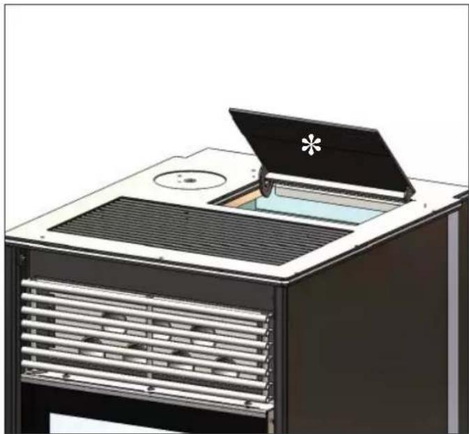
FILLING THE PELLET HOPPER
To access to the hopper open the door * (fi g.1)
N.B.
1) During this operation, the bag of pellets MUST NEVER be placed on the upper grill, otherwise the plastic bag, coming into contact with the heat, could ruin the paintwork on the top.
2) Use the special glove provided if you load the stove while it is functioning and therefore hot.
natural_image
Illustration of a modern kitchen appliance with a lid open, showing ventilation grilles and a small opening (no text or symbols)fig.1
NOTE regarding the fuel.
KIKKA PLUS is designed and programmed to burn wood pellets with 6 mm diameter.
Pellets are a type of fuel in the form of little cylinders, made from compacted sawdust, compressed under high pressure with no adhesives or foreign materials.
They are sold in bags of 15 kg.
For the stove to function properly, you MUST NOT burn anything else in it. Using other materials (including wood) will render the warranty null and void. Such use is detected by laboratory analyses. Edilkamin has designed, tested and programmed their stoves to guarantee the best performance when pellets with the following characteristics are used:
diameter: 6 millimetres
maximum length: 40 mm
maximum moisture content: 8%
calorifi c value: at least 4100 kcal/kg.
If pellets with different characteristics are used, the stoves must be recalibrated using a similar procedure to that carried out by the DEALER when the stove is ignited the first time.
Using unsuitable pellets may: decrease efficiency; cause malfunctions; stop the stove from functioning due to clogging, dirt on the glass, unburnt fuel, etc.
A simple, visual analysis of the pellets may be carried out:
Good quality: smooth, uniform length, not very dusty.
Poor quality: with longitudinal and transverse cracks, very dusty, various lengths and mixed with foreign matter.
INSTRUCTIONS FOR USE
CONTROL PANEL
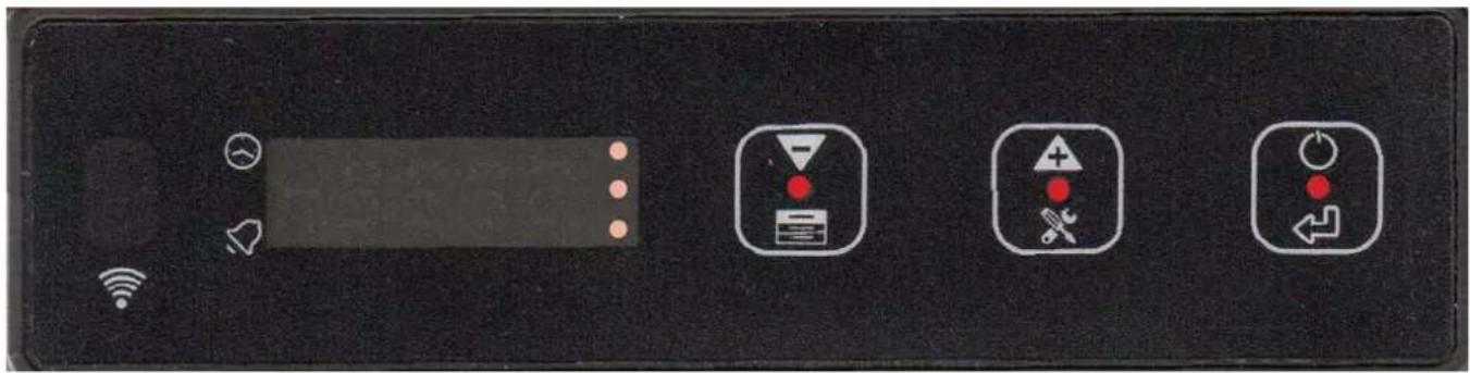
 | Decrease Value, System Information and Fast Programming button | |
 | Increase Value, Parameter Display and Menu button | |
 | “Enter/Confirm” and ON/OFF button | |
 | Timer Operation (thermostat-timer) | |
 | Flashing → button Pressure. ON → Alarm in progress | |
 | Indexing in Parameter Display | |
 | Indexing in Parameter Display | |
 | Indexing in Parameter Display | |
 | If the LED is lit, this means that you can use the button to decrease the value or the selected fi eld | |
 | If the LED is lit, this means that you can use the button to increase the value or the selected fi eld | |
 | If the LED is lit, this indicates the system status (ON/OFF/switching OFF) | |
INSTRUCTIONS FOR USE
LOADING THE SCREW FEEDER (with the stove oFF - Function not active with timer ON)
Loading the pellet screw feeder (coclea) is only necessary if the stove is new (and being switched on for the first time) or if the stove had completely run out of pellets.

To activate this refi ll operation press the cation for a few seconds and scroll down the parameters on the display using the same button until it displays the word "Menu".

Confir rm with the 10 on and scroll down through the

Menu, using the 📄 on until it displays the message

"Load" and confirm with the "on.
By confirming the "Load" option you automatically return to the main screen and the stove is forced to the specific "Load" phase lasting 240 seconds.

To stop prematurely, press the "on holding it down for a few seconds. The stove will return to "oFF". The "Load" sub-menu is available to users only if the stove is OFF.
IGNITION

By pressing the ☐ on, the message “Load” appears on the display (this is the pre-load phase prior to ignition).
The display will then automatically show the message "Strt" and when the pellets have been ignited the word "FirE" appears.
At this point, the stove ignition is completed and it can operate in manual mode or automatic mode.
SWITCHING OFF

If you press the 📋 button for a few seconds, the switch-off phase will start.
During the switch-off phase the words "doWn" and "cooL" appear on the display.
You will not be able to switch the stove back on again; once the switch-off phase is completed, the system will automatically go back to stand-by mode (the word OFF appears on the display).
MANUAL/AUTOMATIC SETTING

Press the button for a few seconds and scroll down the parameters on the display using the same button until it displays the word "Menu".

Confir rm with the on and scroll down through the

Menu, using the 📄 on until it displays the message

"Auto" and confirm with the

To set the AUTOMATIC mode, press the button on and the

message "A on" is displayed. Confirm with the button.

To set the MANUAL mode, press the on and the

message "A off" is displayed. Confirm with the button.
At this point, the word "Auto" appears on the display. Scroll
down through the Menu by pressing the 📄ton and
when the word "quit" is displayed confirm with


button, scroll down by pressing the 📄 on until the
word "quit" is displayed and press the


AUTOMATIC REGULATION

By briefly pressing the button, the message SET ROOM appears on the display, and it sets the value at which you want the stove to work.
To activate the automatic mode, set to “A on” as described in the previous paragraph.
MANUAL REGULATION

By brief y pressing the button, the message SET ROOM

appears on the display, by briefly pressing the button, the message SET POWER is displayed.
You can increase the desired power (from P1 to P5) by pressing


To activate the manual mode, set to "A off" as described in the previous paragraph.

In both regulation modes, by briefly pressing the section, the main screen is displayed.
If no button is pressed within a certain time, the display will show the main screen automatically.
ECO STOP FUNCTION


By briefly pressing the message "E on" is displayed (function ON) or "E off" (function OFF).


To activate the ECO STOP function, press the [icon] on and
the message "E on" is displayed and confirm with the

To deactivate the ECO STOP function, press the on and the message "E off" is displayed and confirm with the

It can only be activated in automatic mode ("A on").
It is a function that is suitable when the stove is installed in small rooms or, during mid-seasons, when even a minimum power setting still tends to overheat the room.
This function is managed automatically, and allows you to switch off the stove when the desired room temperature is exceeded.
When the room temperature falls below the set value, the stove automatically switches back on.
INSTRUCTIONS FOR USE
VENTILATION SETTING

Press the button for a few seconds and scroll down the parameters in the display using the same button until it displays
the term "FAn1" and confirm with the button.
This sub-menu allows you to vary the fan speed.

With the button you can set the speed manually from 0 to 10, or set the speed to automatic mode ("Auto").
SETTING DATE AND TIME

Press the 📄 on for a few seconds and scroll down the parameters on the display using the same button until it displays the word "Menu".
Confir rm with the button and scroll through the Menu

using the "Button" until it displays the word "Time" (to set the time) or the word "Date" (to set the date) and confirm with

Once you have selected the "Time" setting, you can enter the sub-menu dedicated to setting the hours ("Hour") and minutes ("Min").
To increase/decrease the hours and/or minutes, you always use


the anchor

Confirm with the button.
To return to the previous Menu display, select "quit".


on and press the

until it displays the word "quit" and press the London. Once you have selected the setting "Date", you can enter the sub-menu for setting the day ("Days"), month ("Mont") and year ("Year").
To increase/decrease the hours and/or minutes, you always use


the and/or

Confirm with the button.
To return to the previous Menu display, select "quit".


on and press the

until it displays the word "quit" and confirm with the button.

SETTING DUCTING

on for a few seconds and scroll down the e display using the same button until it displays
the term "FAn2" and confirm with the button.
The regulations admitted for the canalisation are the same that for ventilation
ACTIVATING THE THERMOSTAT-TIMER

on for a few seconds and scroll down on the display using the same button until it is rd "Menu".
Confirm with the ^1 on and scroll down through the Menu, using the ^2 on until it displays the message

on and scroll down through the

n until it displays the message


"ProG" and confirm with the "con".
To activate the thermostat-timer, press the button and the message "P on" is displayed.


Confirm with the
At this point, the LED indicating that the termostat-timer is active is displayed
To deactivate the thermostat-timer, press the

and the message "P off" is displayed. Confirm with the button.
At this point, the word "ProG" appears on the display. Scroll down through the Menu by pressing the 📄 on and
when the word "quit" is displayed confirm with button, but ton, scroll down by pressing the button until the word
"quit" is displayed and press the


INSTRUCTIONS FOR USE
SETTING THE THERMOSTAT-TIMER

Press the button for a few seconds and scroll down the parameters in the display using the same button until it displays

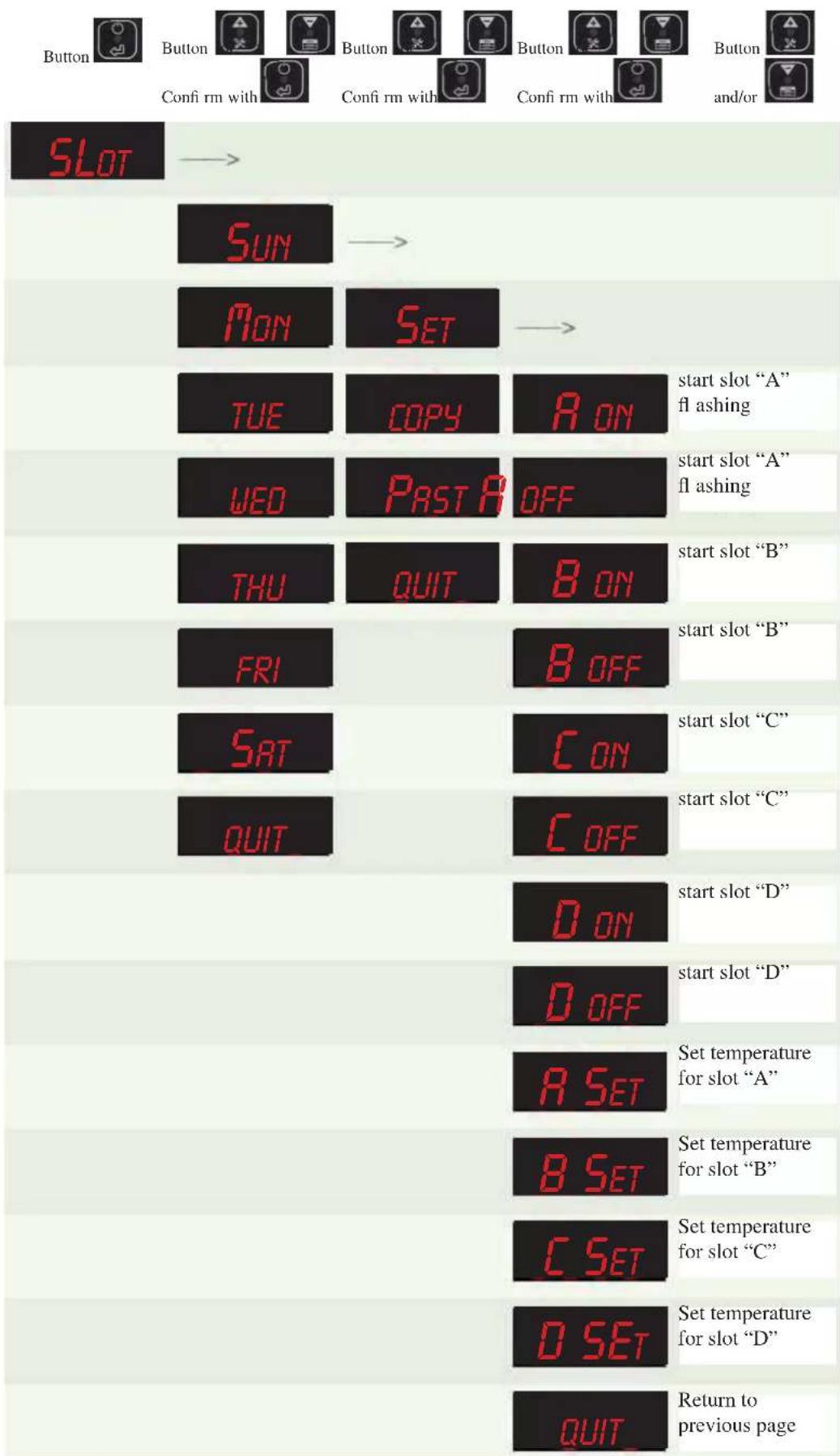
the term "SLot" and confirm with the button.
This sub-menu allows you to set various time zones for the correct operation of the system with the timer programming active (P on).
To activate the functions see the previous paragraph.


With the 📄 and 📋ons you can select the day of the week and set the times for the stove to switch itself ON and
OFF.

Using the 📄 can confirm the settings (day of week, time for the stove to switch itself ON and OFF).
By selecting the day of the week, as described above, use "SET" and confirm.
For the day of the week selected, you can set switch-on "on A" and switch-off "off A" and also set the room "SEt A". You can set up to a maximum four daily time slots(A, b, c, d).
WARNING: if you do not wish to use all the time slots scheduled for the day, enter the ignition ON and OFF within the same schedule.
To speed up the programming operations, you can copy the daily schedule for the other days of the week.
Select the day of week that you want to copy, confirm, then select the message "coPy" on the display and confirm.
Select the day of the week in which you want to copy the daily schedule and confirm.
With the 🔊 and 🔒 buttons select the message "PASt" and confirm.
ADJUSTING THE FLAME
We recommend that this setting is only modified by the DEALER.
It allows you to correct the calibration of the stove and change the fume fan speed and the screw feeder motor.
Press the button for a few seconds and scroll down the parameters in the display using the same button until it displays
the term "PELL" and confirm with the button.
With the 📄️ button, you can make the settings as follows:
| PARAMETER FLAME | |
| 0 DEFAULT | |
| 1++ | |
| 2 | + |
| -1- | |
| -2-- | |

Confirm with the button.
INSTRUCTIONS FOR USE
PROGRAMMING EXAMPLES
INSTRUCTIONS FOR USE
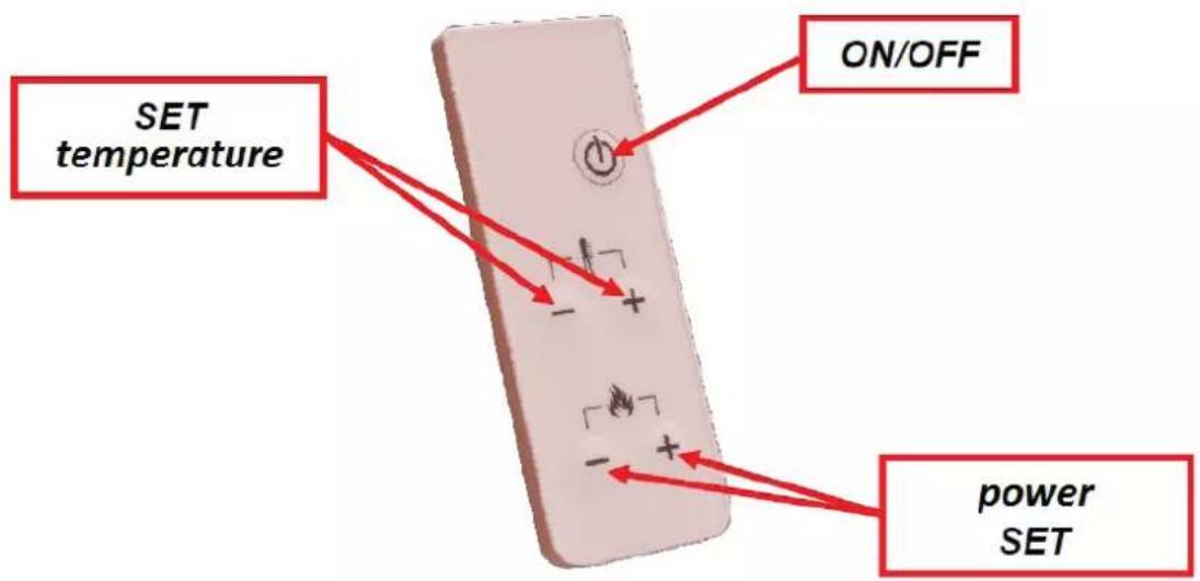
REMOTE CONTROL (optional)
The display panel has an IR receiver.
When the panel is in the main viewing screen, signals from the remote control can be accepted which allow you to:
- Switch the stove ON and OFF using the ON/OFF button.
- Increase/Decrease Room Temperature Setting using the buttons shown above.
- Increase/Decrease the Power Setting using the buttons shown above.
In the last two cases the display will flash as during the other programming phases.
INFORMATION FOR USERS
In accordance with Art. 13 of the Legislative Decree No. 151, dated 25 July 2005, “Implementation of Directives: 2002/95/EC, 2002/96/EC and 2003/108/EC, pertaining to the reduction of hazardous substances used in electrical and electronic equipment, as well as disposal of waste”.
The crossed-out wheeled bin symbol shown on the equipment or on the packaging indicates that the product must be disposed of separately at the end of its useful life. Therefore, at the end of the equipment's useful life, the user must hand in the equipment to suitable collection facilities for electrical and electronic waste, or return it to the retailer when a new, equivalent appliance is purchased in a ratio of one to one.
MAINTENANCE
Before performing any maintenance, disconnect the appliance from the mains.
Regular maintenance is required for the stove to function correctly.
Any problems resulting from lack of maintenance will immediately void the warranty.
N.B.
- Any unauthorised modification is forbidden
- Use spare parts recommended by the manufacturer
- The use of counterfeit parts results in the guarantee becoming null and void
DAILY MAINTENANCE
Operations must be performed when the stove is off, cold and unplugged from the power supply
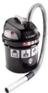
- Cleaning must be carried out with a vacuum cleaner. (see optional extras page 52).
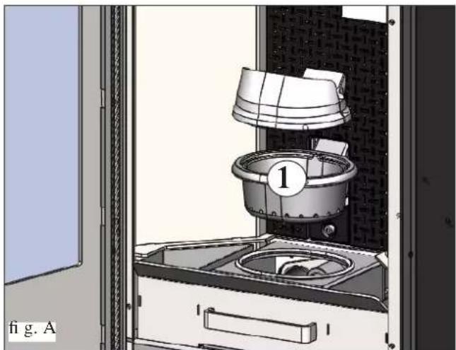
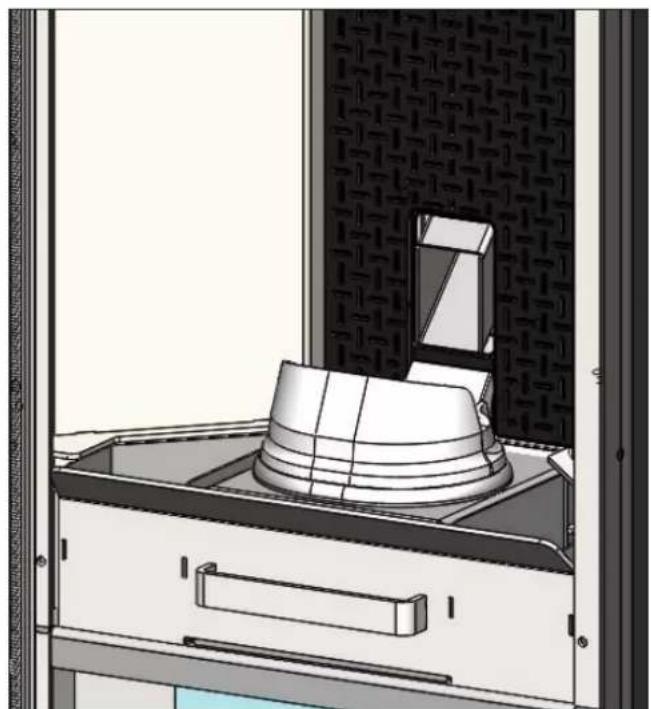
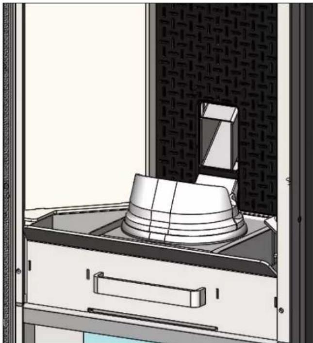
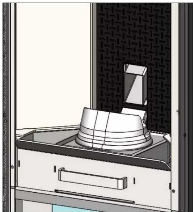
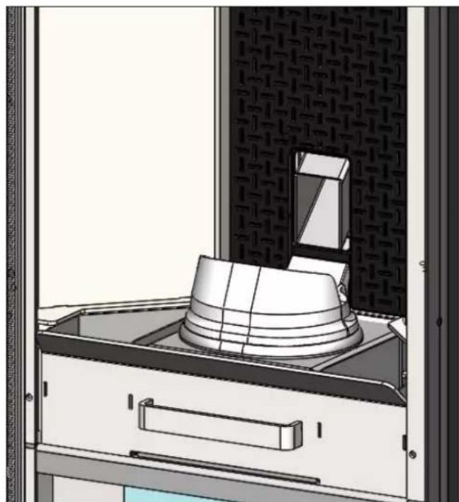
- Open the door, extract the fire box (1 - fig. A) and tip the residue into the ash drawer (2 - fig. B).
- DO NOT EMPTY THE RESIDUE OUT INTO THE PELLET HOPPER.
- Pull the ash drawer (2 - fi g. b) out and empty it into a non-fl ammable container (the ash may still have some parts that are hot and/or embers).
• Vacuum out the inside of the fire box, fire grate, and space around the fire box, into which the ash falls. - Remove the fire box (1 - fig. A) and remove any encrustation using the brush provided, clearing any clogging in the holes.
• Vacuum the fire box, clean the contact edges between the fire box and its seating. - Clean the glass, if necessary (when cold).
Never vacuum hot ash, it can make the vacuum cleaner breakdown and represents a fi re risk.
ATTENTION:
MAKE SURE THE ASH TRAY IS CORRECTLY POSITIONED IN ITS HOUSING
WEEKLY MAINTENANCE
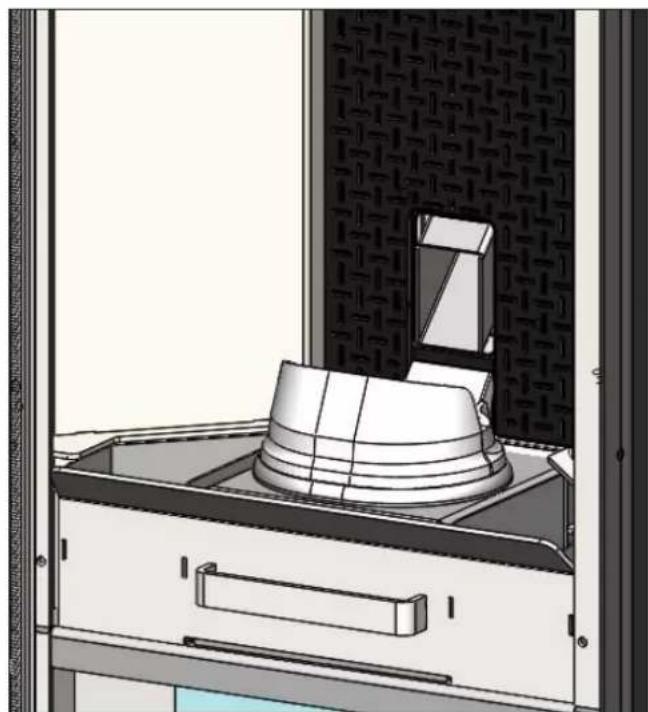
- Remove the ceiling (3 - fi g. C) and tip the residue into the ash drawer (2 - fi g. B).
The ceiling is a component subject to wear, Edilkamin does not accept responsibility for it, more so if any breaks are due to extracting or putting it back in its seating.
MONTHLY MAINTENANCE
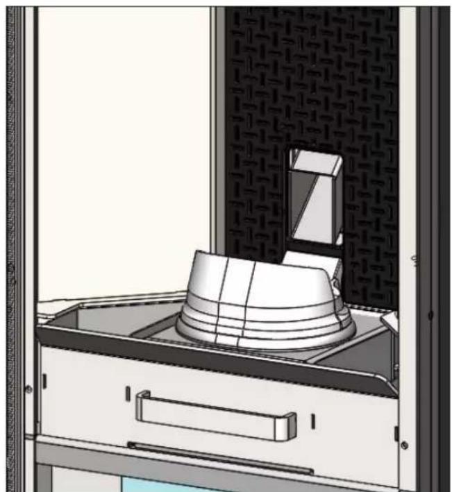
In case of fl ue outlet from the top (page 28) clean the internal part of the connecting band removing the inspection (4 - fi g. D)
natural_image
3D rendering of a mechanical device with a labeled component (1) and no visible text or symbols on the main structure.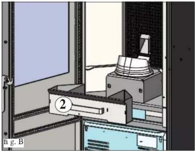
natural_image
Interior view of a laboratory or industrial chamber with equipment and a numbered component (no visible text or symbols)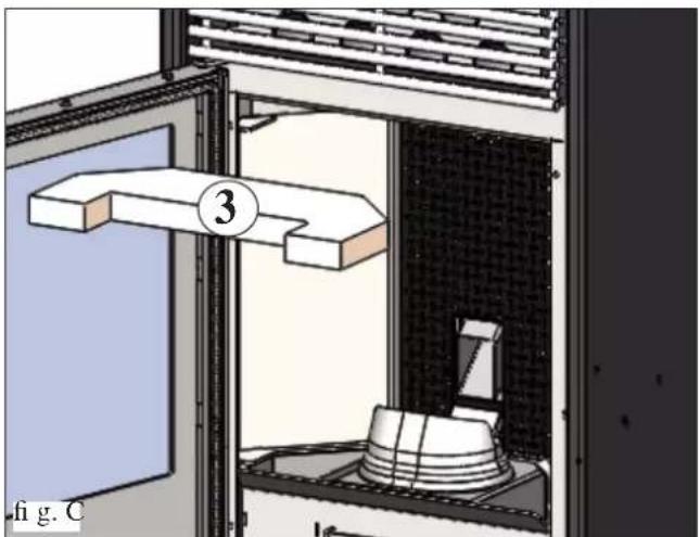
natural_image
Diagram of a laboratory setup with a labeled component (3) and a base, showing no readable text or symbols.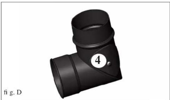
natural_image
3D rendering of a black T-shaped pipe fitting with a numbered circle (4) and label 'fig. D' below (no text or symbols on the object itself)MAINTENANCE
(implemented by the DEALER)
Consists of:
- Clean the stove internally and externally
- Thorough cleaning of the heat exchange piping inside the hot air outlet grille located in the upper part of the front of the stove
- Carefully clean and remove dirt from the combustion chamber and the relative compartment
- Clean fans, verify mechanical and clamp loosening
- Clean smoke channel (replace seals on smoke exhaust pipe)
- Clean fume probe.
- Clean smoke duct especially if
- Visual check of power cables, connections and power cord.
- Clean the pellet hopper and check loosening of the feed screw - gear motor assembly
- Clean/check the Synoptic Panel
- Check the small pressure-switch pipe, and replace when necessary
- Replace the door seal
- Functionality test: load the feed screw, ignite, let it run for 10 minutes and shutdown
If the stove is used very frequently, it is advisable to clean the smoke channel and the fume duct every 3 months.
ATTENTION !!!
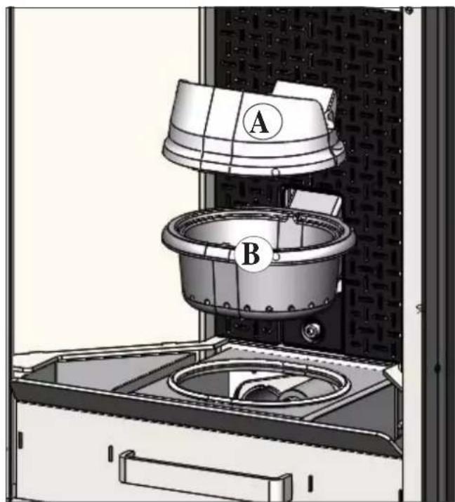
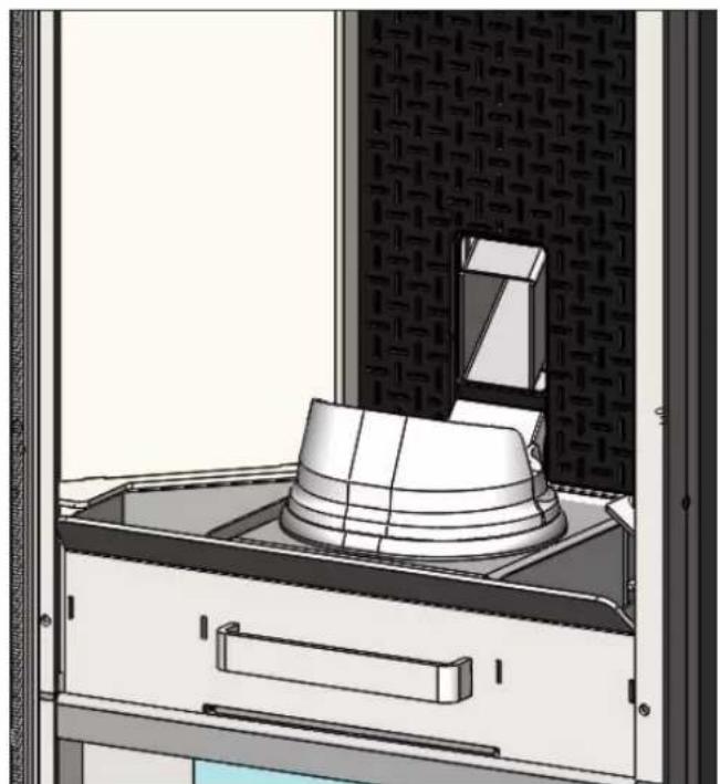
After implementing a normal cleaning procedure, INCORRECT coupling of the upper (A) (fi gura 1) and lower (B) (fi gura 1) combustion chambers can compromise the stove's performance.
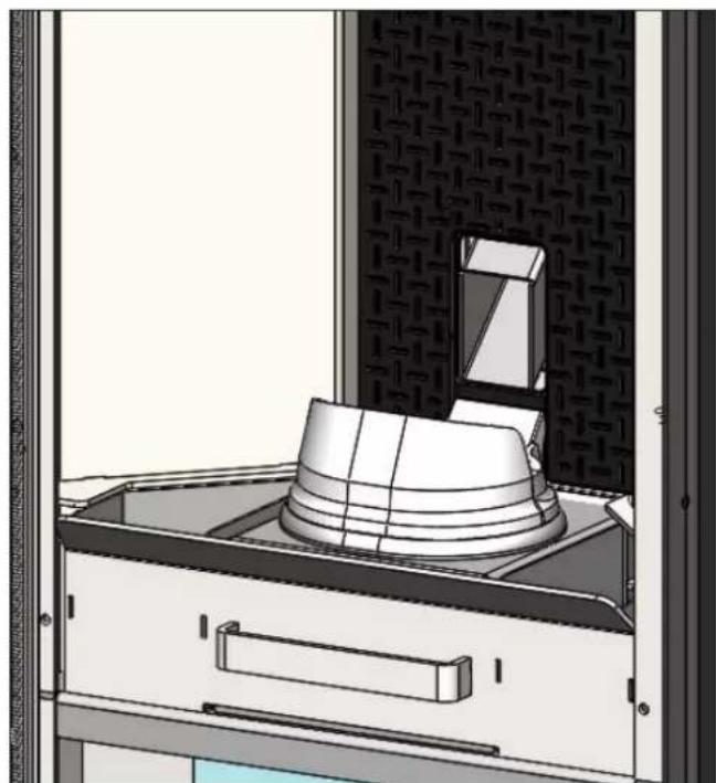
Before igniting the stove, make sure the combustion chambers are correctly paired as indicated in (fi g. E) without ash or unburnt material present on the support perimeter.
We remind you that using the stove without cleaning the melting pot, may cause a sudden ignition gas inside the combustion chamber with the consequent breaking of the glass
natural_image
Technical diagram of a mechanical device with labeled components A and B, showing internal components and housing (no text or symbols beyond labels)fig.1
natural_image
3D rendering of a kitchen appliance with a lid and handle, no visible text or symbolsfig.2
POSSIBLE TROUBLESHOOTINGPOSSIBLE TRO
In the event of problems the stove stops automatically and runs the shutdown process and the display shows text regarding the motivation of the shutdown (see the various alarms below).
Never pull the plug during shutdown on account of malfunction.
If the stove shuts down, you need to let the Switch-off procedure finish before you can restart the stove.
Do not turn the stove on again before checking the cause of the malfunction and CLEANING/ EMPTYING the crucible.
INDICATION OF POSSIBLE CAUSES OF MALFUNCTION AND INDICATIONS AND REMEDIES:
1) Signalling: AL 01 fume probe faulty or disconnected
Problem: Shutdown due to faulty or disconnected fume probe
Actions: • Check the fume probe connection to the board: check the operation with a cold test (DEALER).
2) Signalling: AL 02 Room sensor fault (this is activated if the probe is faulty or disconnected)
Problem: Shutdown due to detected temperature anomaly
Actions: • Check the connection of the probe to the circuit board (DEALER)
- Check the operation of the sensor (DEALER)
3) Signalling: AL07 Thermal safety (this occurs when the safety thermostat, located on the pellet slide, trips due to over-temperature in the pellet tank)
Problem: Excessive loading of pellets
Actions: Check operation of motor (DEALER)
4) Signalling: AL 08 depressurisation lacking (this occurs when there is not sufficient draft in the cold air intake pipe)
Problem: The screw feeder is stopped
Actions: • Check that the cold air pipe is not obstructed
- Check the pressure switch
- Check that the silicone tube is not clogged
5) Signalling: AL 09 Failure of fume expulsion motor (this trips if the smoke extraction speed sensor detects a fault)
Problem: Shutdown for smoke extraction speed fault detection
Actions: • Check smoke extractor function (devolution sensor connection) and board (DEALER).
- Check smoke channel for dirt • Verify the electrical system and earthing system.
- Check electronic circuit board (DEALER).
6) Signalling: AL 10 Failed ignition (intervences if a flame fails to appear within a maximum of 20 minutes, or if ignition temperature is not reached).
Problem: Turns off due to incorrect smoke temperature during ignition
Distinguish either of the following cases:
Flame does NOT appear
Actions: Check: - combustion chamber position and cleanliness;
- arrival of combustion air in the combustion chamber;- if the heating element is working (DEALER);
- room temperature (if lower than 3^ C use a firelighter) and damp. - Try to light with a firelighter.
Flames appear, but AF appears on the display after Ar.
Actions: Check: (only by the Dealer)
- • fume probe operation (DEALER);
- start-up temperature setting in the parameters (DEALER).
POSSIBLE TROUBLESHOOTINGPOSSIBLE TRO
7) Signalling: AL 11 Stop/Flame: (this occurs if the fume probe detects a fume temperature lower than the set value and interprets this as the absence of flames)
Problem: Turns off due to drop in smoke temperature
Flame may fail for any of the following reasons:
Actions: - lack of pellets
- too many pellets have suffocated the flame, check pellet quality (DEALER)
- Check whether the maximum thermostat has caused the problem (rare circumstance since this would correspond to over heated fumes (technical assistance centre)
- Check whether the pressure switch has cut off electricity to the gear motor because of a blocked flue or other problem.
8) Signalling: AL 13 over heated fumes (turns off due to exceeding maximum smoke temperature).
Problem: Switches off because of overheated fumes.
Over heated fumes may depend on: type of pellets, anomalous fume extraction, blocked channel, incorrect installation, gear motor drift, lack of air vents in the room.
9) Signalling: AL 14 Overheating of the electronic control board (this occurs if the temperature of the electronic board is
higher than 70^ C)
Problem: Shutdown due to exceeding maximum temperature of electronic control board.
Actions: Check the functionality of the room fan, and motor (DEALER)
- Check the operation of the electronic control board (DEALER)
10) Signalling: BOUT black out stop (not a defect of the stove).
Problem: Turns off due to lack of electricity
Actions: • Check electricity connection and drops in voltage.
CHECK LIST
To be integrated with a complete reading of the technical specifications
Positioning and installing
• First ignition performed by authorised CAT who released the guarantee certificate
• Air vent in the room
• Only the stove outlet passes through the smoke channel/chimney flue
• Features of the smoke channel (stretch of duct connecting the stove to the flue/chimney):
• a maximum of 3 curves.
a maximum 2 horizontal metres
• Chimney pot that is high enough to avoid downdraft areas
• The discharge pipes are made of a suitable material (stainless steel is recommended)
• When using any flammable materials (e.g. wood), all precautions have been taken to prevent a fire hazard
Use
• Good quality, dry pellets are used
• The chimney pot and ash compartment are clean and well positioned
• The door is closed properly
• The combustion chamber is inserted properly into the relevant compartment
REMEMBER TO VACUUM THE COMBUSTION CHAMBER BEFORE EACH IGNITION Should ignition fail, DO NOT re-ignite until you have emptied the combustion chamber.
OPTIONAL
TELEPHONE DIALLER FOR REMOTE IGNITION
The stove can be ignited remotely by asking the DEALER to connect the telephone combiner to the serial port behind the stove via the optional cable.
• REMOTE CONTROL
- KIT 12 to channel hot air to an adjacent room
- KIT 12 Bis to channel hot air to a remote room
CLEANING ACCESSORIES

GlassKamin
Used for cleaning the ceramic glass
natural_image
Black and white photo of a LIPAN vacuum cleaner with attached hose (no visible text or symbols)Ash vacuum cleaner
User for cleaning the hearth
NOTES
DATE AND STAMP INSTALLER
DATE AND STAMP CAT. FIRST IGNITION
DATE AND STAMP ANY SERVICING
DATE AND STAMP SEASONAL MAINTENANCE
DATE AND STAMP DEALER
DATE AND STAMP CAT.
For further clarification or requirements, visit our website www.edilkamin.com
NOTES:
TABLE DES MATIÈRES
natural_image
Close-up of a mechanical component with wires and a paper sheet, no visible text or symbolsINFORMATIONS GÉNÉRALES
EVACUATION DES FUMEES
natural_image
Black industrial device with ventilation slots and a label 'fi g. 1' at the bottom (no visible text on device body)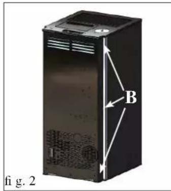
natural_image
Interior view of a server rack unit with labeled section A, showing internal components and ventilation ducts (no text or symbols beyond labels)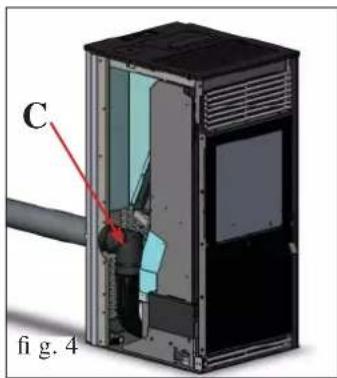

natural_image
Cross-sectional diagram of a device showing internal components and labeled parts (no readable text or symbols)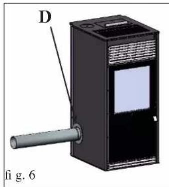
natural_image
3D diagram of a device with labeled component D and pipe, no readable text or symbols present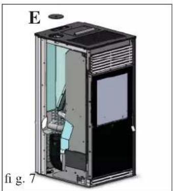
natural_image
Cross-sectional diagram of a device casing with internal components, labeled 'E' and 'fig. 7' (no text or symbols on the diagram itself)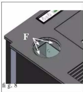
natural_image
3D diagram of a device casing with labeled component G, no readable text or symbols present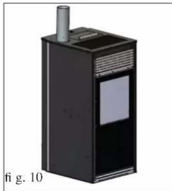
natural_image
3D rendering of a black industrial device with a cylindrical inlet and label, labeled 'fi g. 10' (no other text or symbols)SORTIE DES FUMÉES
natural_image
Technical line drawing of a mechanical or structural assembly with no visible text or symbols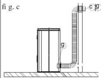
CANALISATION DE L'AIR CHAUD
KIT 12 BIS (code 778160) (optional) POUR CANALISER L'AIR CHAUD DANS UNE PIÈCE ÉLOIGNÉE DE CELLE OÙ LE POÊLE EST INSTALLÉ
Composants :
N.B. : LA PARTIE INITIALE DU TUYAU FLEXIBLE DOIT ÊTRE « ÉTENDUE » COMPLÈTEMENT DE MANIÈRE A ÉLIMINER LE PLISSEMENT. DE CETTE FAÇON, LE DIAMÈTRE INTÉRIEUR S'ÉLARGIRA SENSIBLE- MENT, CE QUI FACILITERA L'ASSEMBLAGE.
Procédure
natural_image
Illustration of a modern air purifier with a lid open, showing ventilation grilles and a small vent (no text or symbols)fig.1
natural_image
Technical illustration of a portable air purifier with labeled component (1), no text or symbols present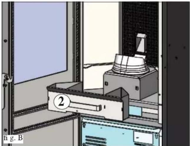
natural_image
Interior view of a laboratory or lab equipment room with a labeled device and a numbered component (no readable text or symbols)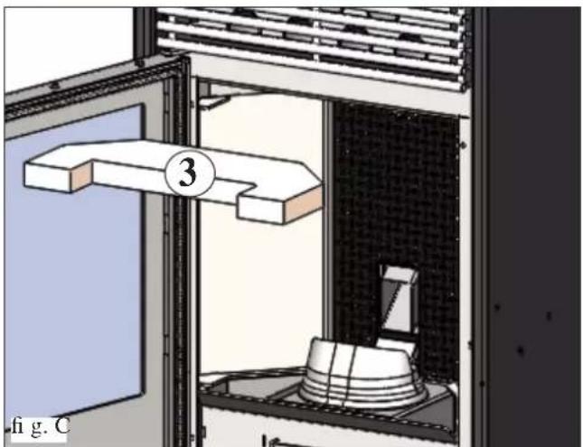
natural_image
Diagram of a laboratory apparatus with a numbered component (3) and a base, showing internal components without any text or symbols.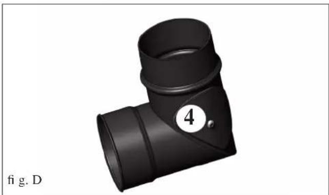
natural_image
3D rendering of a black T-shaped pipe fitting with a numbered label (4) and figure marker (fi g. D), no text or symbols on the object itself.ENTRETIEN
ENTRETIEN SAISONNIER (par le revendeur)
Consiste en:
natural_image
Technical diagram of a mechanical device with labeled components A and B, showing internal components without any readable text or symbols.fig.1
natural_image
3D rendering of a kitchen appliance with a lid and handle, showing internal structure without any text or symbols.fig.2
CONSEILS EN CAS D'ÉVENTUELS INCONVÉNIENTS
Inconvénient: Charge de pellets excessive
natural_image
Black and white photo of a Linen air purifier with attached hose and control panel (no visible text or symbols)natural_image
Close-up of a mechanical component with wires and a paper sheet, no visible text or symbolsINFORMACIÓN GENERAL
FRENTE VUELTA
LADO
PLANTA
INFORMACIÓN GENERAL
natural_image
Black industrial device labeled 'fig. 1' with no visible text or symbols on its body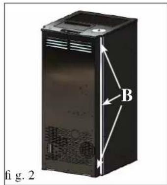
SALIDA DE HUMOS
natural_image
Interior view of a server rack unit labeled A, showing internal components and ventilation ducts (no text or symbols beyond labels)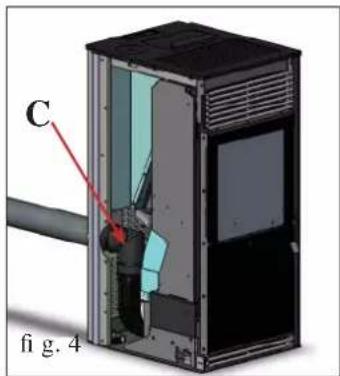
natural_image
Cross-sectional diagram of a device showing internal components and a red arrow indicating direction (no text or symbols present)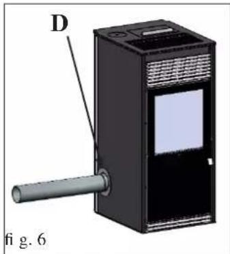
natural_image
3D diagram of a device with labeled component D and pipe, no readable text or symbolsnatural_image
3D diagram of a device interior with labeled components (E and fig. 7), showing internal compartments and no readable text or symbols.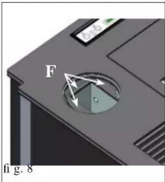
natural_image
3D rendering of a black industrial device with a cylindrical inlet and label 'fi g. 10' (no readable text or symbols on the device itself)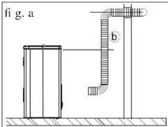
natural_image
Simple line drawing of a vertical pipe system with a rectangular tank and a curved pipe (no text or symbols)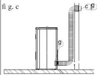
NOTA: LA PARTE INICIAL DEL TUBO FLEXIBLE DEBE ESTAR "EXTENDIDA" COMPLETAMENTE DE MODO QUE ELIMINE EL PLIEGUE; DE ESTE MODO EL DIÁMETRO INTERNO SE ENSANCHARÁ SENSIBLE- MENTE FAVORECIENDO LA ENTRADA.
natural_image
Illustration of a modern kitchen appliance with a lid open, showing ventilation grilles and a small opening (no text or symbols)fig.1
natural_image
Technical illustration of a mechanical device with a labeled component (1), showing internal components and housing (no text or symbols beyond label)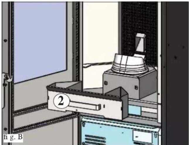
natural_image
Interior view of a laboratory or lab equipment room with a labeled device and a numbered component (no readable text or symbols)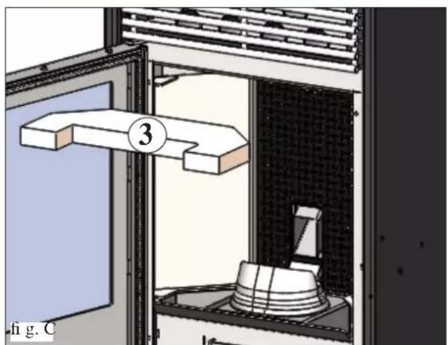
natural_image
Technical diagram of a mechanical testing setup with labeled component 3, no readable text or symbols present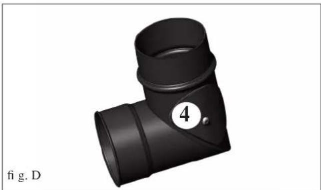
natural_image
3D rendering of a black T-shaped pipe fitting with a numbered circle (4) and label 'fig. D' below (no text or symbols on the object itself)MANTENIMIENTO
natural_image
Technical diagram of a mechanical device with labeled components A and B, showing internal components and housing (no text or symbols beyond labels)fig.1
natural_image
3D rendering of a kitchen appliance with a dome-shaped lid and handle, mounted on a tray (no text or symbols visible)fig.2
CONSEJOS PARA POSIBLES INCONVENIENTES
natural_image
Black and white photo of a vacuum cleaner with attached hose and control panel (no visible text or symbols)Bidón aspira cenizas
natural_image
Close-up of a mechanical component with wires and a paper sheet, no visible text or symbolsALLGEMEINE INFORMATIONEN
natural_image
Black industrial device labeled 'Abb. 1' with no visible text or symbols on the device itself.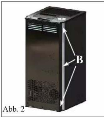
RAUCHABZUG
natural_image
3D rendering of an industrial electronic device with labeled components (A, 1, Abb. 3), no readable text or symbols beyond labels.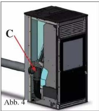
natural_image
3D cutaway diagram of an electronic device showing internal components and casing (no text or symbols)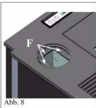
natural_image
3D rendering of a black industrial device with a cylindrical top and rectangular base (no visible text or symbols)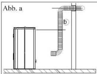
KANALISIERUNG DER WARMLUFT
SET 12 BIS (Cod. 778160) (optional) ZUR KANALISIERUNG DER WARMLUFT IN EINEN ENTFERNTEREN RAUM, ZUSÄTZLICH ZUM OFENAUFSTEL- LUNGSRAUM
natural_image
3D rendering of a modern kitchen appliance with a lid open, showing ventilation grilles and a small opening (no text or symbols visible)Abb. 1
natural_image
Technical illustration of a portable air purifier with labeled component (1), no readable text or symbols beyond label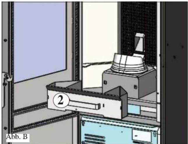
natural_image
Interior view of a laboratory or lab equipment setup with a labeled component (2) and no visible text or symbols.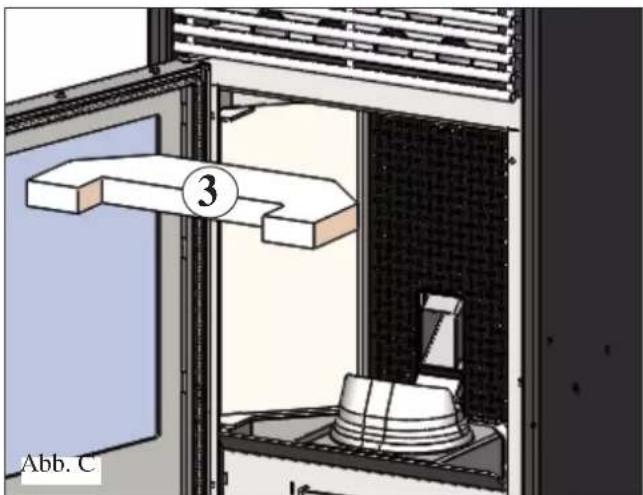
natural_image
Technical diagram of a mechanical testing setup with labeled component (3), no readable text or symbols beyond label and number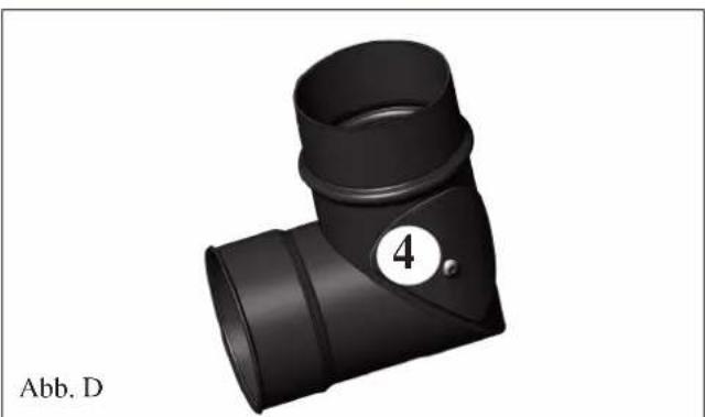
natural_image
3D rendering of a black T-shaped pipe fitting with a numbered label (4) and Abb. D label below (no text or symbols on the object itself)WARTUNG
natural_image
Technical diagram of a mechanical device with labeled components A and B, showing internal components and housing (no text or symbols beyond labels)Abb. 1
natural_image
3D rendering of a kitchen appliance with a dome-shaped lid and handle, mounted on a drawer (no text or symbols visible)Abb. 2
TROUBLE SHOOTING
natural_image
Black and white photo of a vacuum cleaner with attached hose and control panel (no visible text or symbols)Afb. 1
ALGEMENE INFORMATIE
natural_image
Close-up of a mechanical component with wires and a paper sheet, no visible text or symbolsALGEMENE INFORMATIE
FRONT
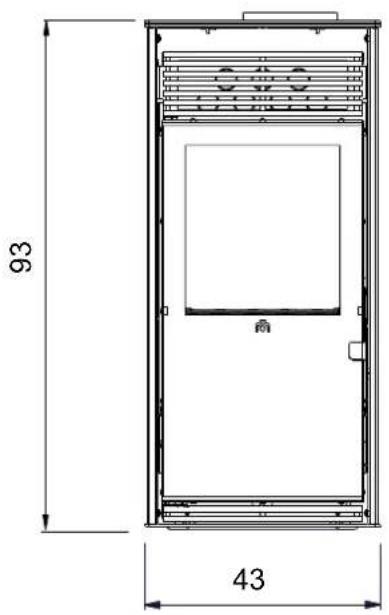
TUREG
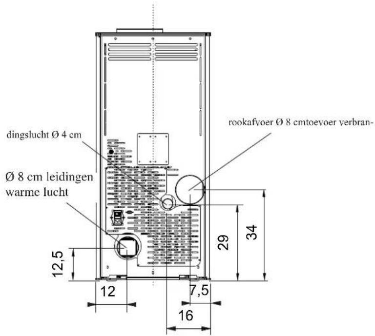
KANT
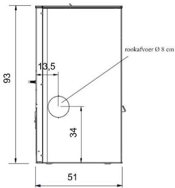
PLAN
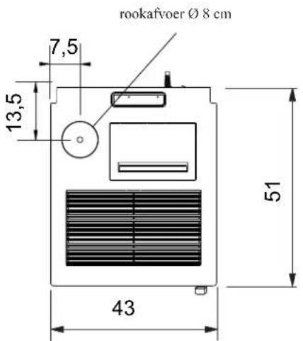
ALGEMENE INFORMATIE
natural_image
Black industrial machine with ventilation slots and a label 'afb. 1' at the bottom (no visible text on device body)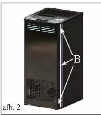
ROOKGASAFVOER
natural_image
3D rendering of an electronic device casing with labeled components (A, I, afb. 3), no readable text or symbols beyond labels.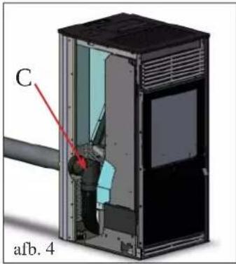
natural_image
3D rendering of a black industrial device with a cylindrical shaft and labeled component D (no text or symbols on the device itself)AANSLUITING ZIJDELINGSE ROOKGASAFVOER
natural_image
Close-up of a computer floppy disk with a labeled component 'F' and directional arrows indicating motion (no text or symbols beyond the label)natural_image
3D rendering of a black industrial device with a cylindrical top and label (no visible text or symbols)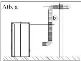
KANALISATIE WARME LUCHT
KIT 12 BIS (code 778160) (optie)
VOOR HET KANALISEREN VAN WARME LUCHT IN EEN VERDER GELEGEN RUIMTE, BOVENOP DEZE VAN INSTALLATI
Samenstelling:
N.B.:
HET BEGIN VAN DE FLEXIBELE LEIDING MOET HELEMAAL "UITGEREKT" WORDEN ZODAT DE INTERNE DOORSNEDE AANZIENLIJK GROTER WORDT. DIT VEREENVOUDIGT DE AANSLUITING.
natural_image
Illustration of a modern air purifier or oven with a lid open, showing ventilation grilles and a small vent (no text or symbols)Afb.1
OPMERKING betreffende de brandstof.
ACTIVERING CHRONOTHERMOSTAAT

INSTELLING CHRONOTHERMOSTAAT

AFSTANDSBEDIENING (optioneel):
natural_image
Technical illustration of a portable air purifier with labeled component (1), no readable text or symbols beyond label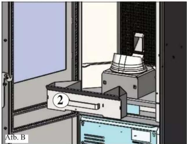
natural_image
Interior view of a laboratory or lab equipment room with a labeled control panel and equipment (no visible text or symbols)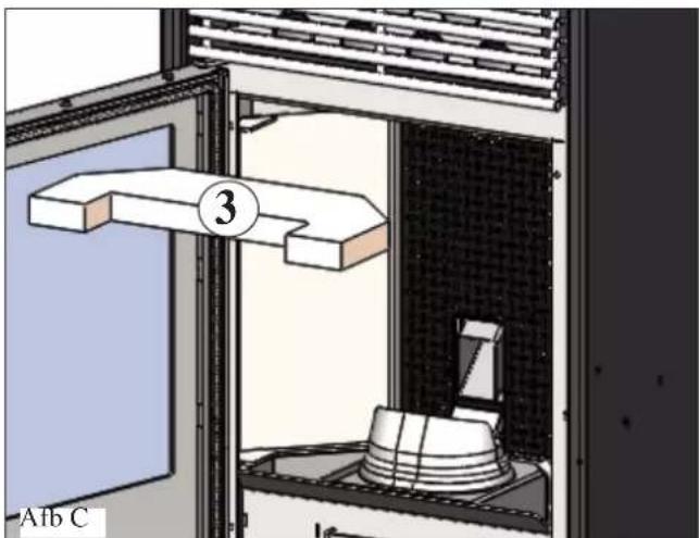
natural_image
Diagram of a laboratory setup with a labeled component (3) and a base, showing no readable text or symbols.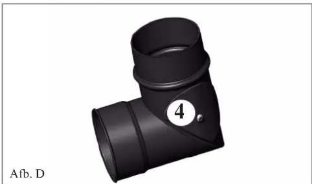
natural_image
3D rendering of a black T-shaped pipe fitting with a numbered circle highlighting part 4 (no text or symbols on the object itself)ONDERHOUD
SEIZOENSGEBONDEN ONDERHOUD
(door uw Dealer)
Bestaat uit:
natural_image
Technical diagram of a mechanical device with labeled components A and B, showing internal components and housing (no text or symbols beyond labels)afb. 1
natural_image
3D rendering of a kitchen appliance with a dome-shaped lid and handle, mounted on a drawer (no text or symbols visible)afb. 2
ADVIES VOOR MOGELIJKE PROBLEMEN
natural_image
Black Lirard pump with attached hose and control panel (no visible text or symbols)Aszuiger
natural_image
Close-up of a mechanical component with wires and a paper sheet, no visible text or symbolsGENERELLE OPLYSNINGER
FORSIDE
BAGSIDE
A: isoleret skorstensrør i stål i henhold til EN 1856
natural_image
Black industrial device with ventilation slots and a label 'fi g. 1' at the bottom (no visible text on device body)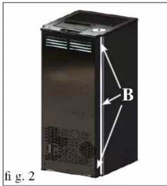
R∅GUDGANG
natural_image
3D rendering of an open industrial device casing with labeled components (A and fig. 3), no readable text or symbols beyond labels.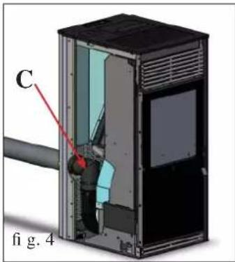
natural_image
3D diagram of a device with labeled component D and pipe, no readable text or symbols beyond labelsTILSLUTNING AF R∅GUDGANG I SIDEN
natural_image
3D cutaway diagram of an electronic device showing internal components and casing (no text or symbols)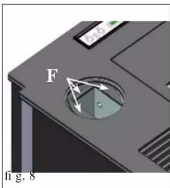
natural_image
Interior view of a device casing with labeled component G, no visible text or symbols beyond label and arrow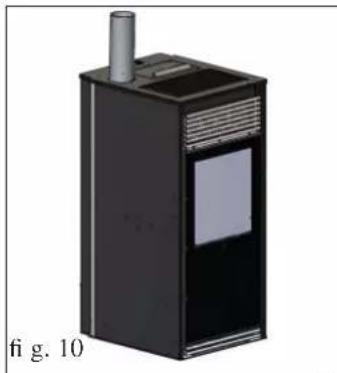
natural_image
3D rendering of a black industrial device with a cylindrical top and label 'fi g. 10' (no readable text or symbols on the device itself)NÅR TILSLUTNINGEN AF R∅GUDLEDNINGSR∅RET TIL SKORSTENSR∅RET ER FÆRDIG, SKAL DU GEN-MONTERE METALSIDEN.
KANALISERING AF VARM LUFT
KIT 12 (cod. 778150) (optional)
VED KANALISERING AF VARM LUFT I ET TIL-
STÖDENDE LOKALE, UDOVER INSTALLATIONSLO-
KALET
Opbygning:
NB.:
DET INDLEDENDE AFSNIT AF SLANGEN SKAL LIGGE HELT "UDGLATTET" FOR AT ELIMINERE DENS FOLDER; PÅ DENNE MÅDE FOR∅GES DEN INTERNE DIAMETER I ET OMFANG, SOM G∅R PÅSÆTNING NEMMERE.
Procedure:
natural_image
Technical line drawing of a mechanical or structural assembly with no visible text or symbols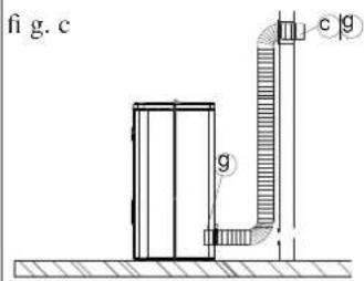
KANALISERING AF VARM LUFT
KIT 12 BIS (cod. 778160) (optional)
VED KANALISERING AF VARM LUFT I ET FJERNT-LIGGENDE LOKALE, UDOVER INSTALLATIONSLO-KALET
Opbygning:
NB: DET INDLEDENDE AFSNIT AF SLANGEN SKAL LIGGE HELT "UDGLATTET" FOR AT ELIMINERE DENS FOLDER; PÅ DENNE MÅDE FOR∅GES DEN INTERNE DIAMETER I ET OMFANG, SOM G∅R PÅSÆTNING NEMMERE.
Procedure:
natural_image
Technical line drawing of a mechanical or architectural component with no visible text or symbols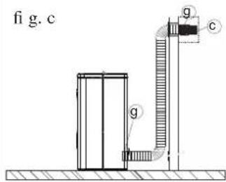
BRUGSANVISNING
OPFYLDNING AF PILLEBEHOLDER
natural_image
Illustration of a modern kitchen appliance with a lid, ventilation grilles, and a small opening (no text or symbols)fig.1
BEM/ERKNING OM BR/ENDSEL
FJERNBETJENING (ekstraudstyr)
natural_image
Technical illustration of a portable air purifier with labeled component (1), no text or symbols present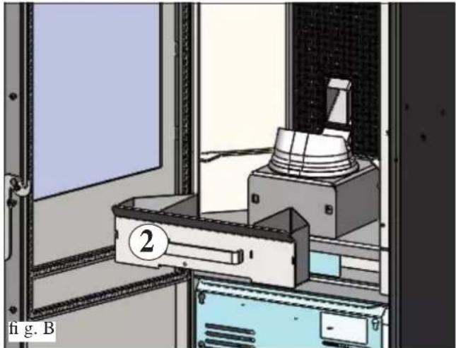
natural_image
Interior view of a laboratory or lab equipment setup with a labeled component (2) and no visible text or symbols.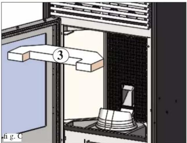
natural_image
Diagram of a laboratory setup with a 3D block labeled '3' and a container, showing no readable text or symbols.
natural_image
3D rendering of a black T-shaped pipe fitting with a numbered label (4) and identifier 'fig. D' below (no text or symbols on the object itself)VEDLIGEHOLDELSE
SÆSONVEDLIGEHOLDELSE
natural_image
Technical diagram of a mechanical device with labeled components A and B, showing internal components and housing (no text or symbols beyond labels)fig.1
natural_image
3D rendering of a kitchen appliance with a lid and handle, showing internal components (no text or symbols visible)fig.2
AFHJÆLPNING AF EVENTUELLE FEJL
natural_image
Black and white photo of a vacuum cleaner with attached tubing (no visible text or symbols)Askestøvsuger
natural_image
Close-up of a mechanical component with wires and a paper sheet, no visible text or symbolsINFORMAÇÕES GERAIS
FRENTE ATRÁS
LATERAL
natural_image
Black industrial machine unit with labeled section 'fi g. 1' (no visible text or symbols on device body)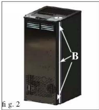
SAÍDAS FUMOS
natural_image
Interior view of a stainless steel industrial device labeled A, showing internal components and ventilation slots (no text or symbols beyond labels)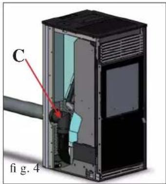
natural_image
Diagram of a device with labeled components (C and ring) and part number (fig. 5), showing internal structure without readable text or symbols.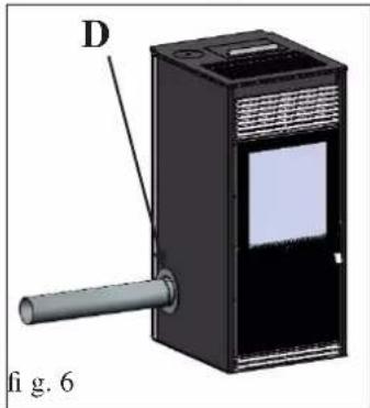
natural_image
3D diagram of a device with labeled component D and pipe, no readable text or symbols presentnatural_image
3D diagram of an open industrial machine with internal components and labeled section E (no text or symbols on the device itself)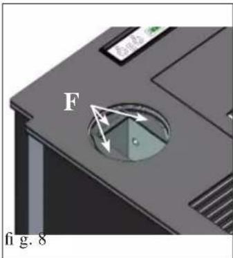
natural_image
3D diagram of a device casing with labeled component G, no readable text or symbols present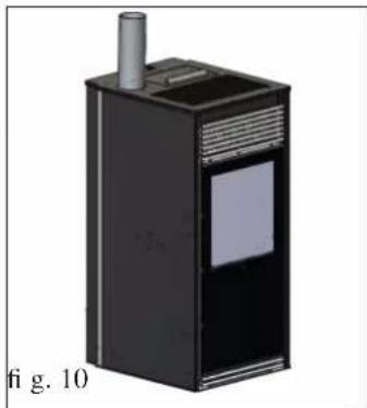
natural_image
3D rendering of a black industrial device with a cylindrical inlet and label, labeled 'fig. 10' (no readable text or symbols on the device itself)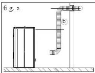
natural_image
Diagram of a pipeline system with a container and pipe, labeled 'fi g. b' (no text or symbols on the diagram itself)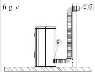
natural_image
Isometric line drawing of a room with a hanging device and labeled components (no text or symbols)OBS.: A PARTE INICIAL DA MANGUEIRA DEVE ESTAR INTEIRAMENTE “ESTICADA” PARA ELIMINAR AS DOBRAS; DESTA FORMA O DIÂMETRO INTERIOR SE ALARGARÁ SENSIVELMENTE E FAVORECERÁ O ENCAIXE.
natural_image
Illustration of a modern kitchen appliance with a lid open, featuring a ventilation grille and a small water tank (no text or symbols visible)fig.1
pre as teclas . Conlinear com a tecla
natural_image
Technical illustration of a portable air purifier with labeled component (1), no text or symbols present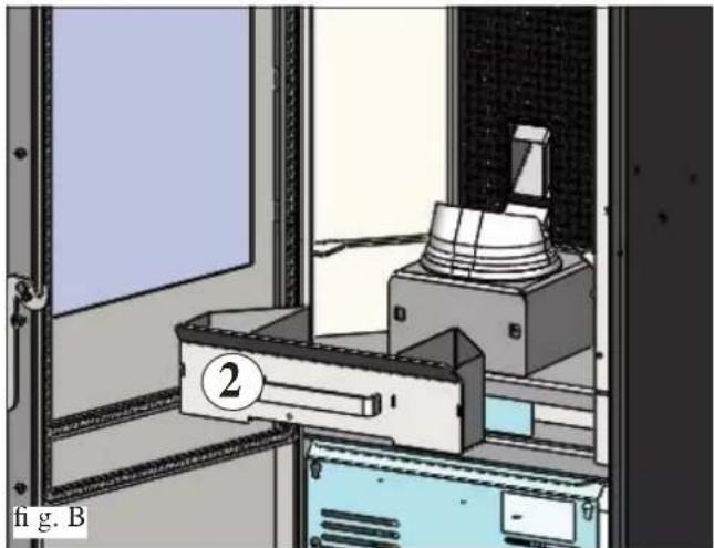
natural_image
Interior view of a laboratory or lab equipment setup with a labeled component (2) and no visible text or symbols.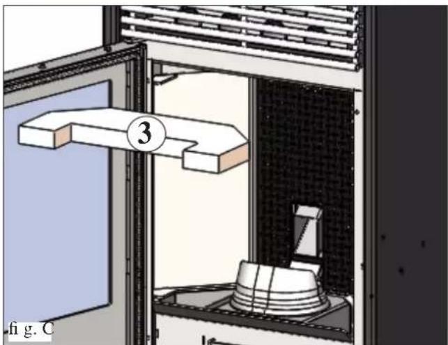
natural_image
Diagram of a laboratory apparatus with a numbered component (3) and a base, showing internal components without any readable text or symbols.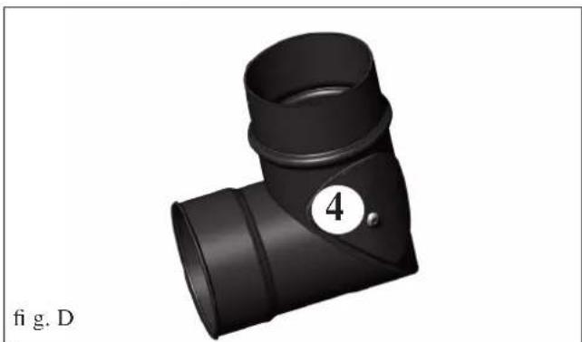
natural_image
3D rendering of a black T-shaped pipe fitting with a numbered circle (4) and label 'fig. D' below (no text or symbols on the object itself)MANUTENÇÃO
natural_image
Technical diagram of a mechanical device with labeled components A and B, showing internal components without any text or symbols.fig.1
natural_image
3D rendering of a kitchen appliance with a lid and drawer, no visible text or symbolsfig.2
CONSELHOS PARA POSSÍVEIS INCONVENIENTES
natural_image
Black and white photo of a vacuum cleaner with attached tubing (no visible text or symbols)Balde para aspirar
- USCITA FUMI
- COLLEGAMENTO USCITA FUMI LATERALE
- COLLEGAMENTO USCITA FUMI DAL TOP
- CANALIZZAZIONE ARIA CALDA
- KIT 12 BIS (cod. 778160)
- N.B.:
- Procedimento:
- TELECOMANDO (optional)
- MANUTENZIONE
- CONSIGLI PER POSSIBILI INCONVENIENTI
- Dear Sir/Madam
- NOTE
- - Commissioning/ testing
- - series number, necessary for identification of the stove, is indicated:
- SAFETY INFORMATION
- GENERAL INFORMATION
- • ELECTRONIC EQUIPMENT
- SAFETY DEVICES
- • SMOKE SENSOR:
- • PRESSURE SWITCH
- • SAFETY THERMOSTAT:
- SERIAL PORT
- BACKUP BATTERY
- FUSE \*
- N.B.
- Declaration of performance
- • CERTIFICATIONS AND BENEFITS \*
- INSTALLATION
- GENERAL NOTES
- VERIFY COMPATIBILITY WITH OTHER DEVICES
- VERIFYTHE POWER SUPPLY CONNECTION (the plug must be accessible)
- AIR INTAKE (mandatory to do)
- POSITIONING AND DISTANCES FOR FIRE SAFETY
- SMOKE OUTLET
- CHIMNEY POT
- SMOKE OUTPUT
- REAR SMOKE OUTPUT CONNECTION
- SIDE SMOKE OUTPUT CONNECTION
- TOP SMOKE OUTPUT CONNECTION
- HOT-AIR DUCTWORK
- Procedure:
- INSTRUCTIONS FOR USE
- FILLING THE PELLET HOPPER
- NOTE regarding the fuel.
- CONTROL PANEL
- LOADING THE SCREW FEEDER (with the stove oFF - Function not active with timer ON)
- IGNITION
- SWITCHING OFF
- MANUAL/AUTOMATIC SETTING
- AUTOMATIC REGULATION
- MANUAL REGULATION
- ECO STOP FUNCTION
- VENTILATION SETTING
- SETTING DATE AND TIME
- SETTING DUCTING
- ACTIVATING THE THERMOSTAT-TIMER
- SETTING THE THERMOSTAT-TIMER
- ADJUSTING THE FLAME
- We recommend that this setting is only modified by the DEALER.
- REMOTE CONTROL (optional)
- INFORMATION FOR USERS
- MAINTENANCE
- DAILY MAINTENANCE
- ATTENTION:
- MAKE SURE THE ASH TRAY IS CORRECTLY POSITIONED IN ITS HOUSING
- WEEKLY MAINTENANCE
- MONTHLY MAINTENANCE
- (implemented by the DEALER)
- ATTENTION !!!
- POSSIBLE TROUBLESHOOTINGPOSSIBLE TRO
- INDICATION OF POSSIBLE CAUSES OF MALFUNCTION AND INDICATIONS AND REMEDIES:
- CHECK LIST
- To be integrated with a complete reading of the technical specifications
- Positioning and installing
- Use
- OPTIONAL
- TELEPHONE DIALLER FOR REMOTE IGNITION
- CLEANING ACCESSORIES
- NOTES
- DATE AND STAMP INSTALLER
- TABLE DES MATIÈRES
- INFORMATIONS GÉNÉRALES
- EVACUATION DES FUMEES
- SORTIE DES FUMÉES
- CANALISATION DE L'AIR CHAUD
- Procédure
- ENTRETIEN
- ENTRETIEN SAISONNIER (par le revendeur)
- CONSEILS EN CAS D'ÉVENTUELS INCONVÉNIENTS
- INFORMACIÓN GENERAL
- SALIDA DE HUMOS
- MANTENIMIENTO
- CONSEJOS PARA POSIBLES INCONVENIENTES
- ALLGEMEINE INFORMATIONEN
- RAUCHABZUG
- KANALISIERUNG DER WARMLUFT
- WARTUNG
- TROUBLE SHOOTING
- ALGEMENE INFORMATIE
- ROOKGASAFVOER
- AANSLUITING ZIJDELINGSE ROOKGASAFVOER
- KANALISATIE WARME LUCHT
- KIT 12 BIS (code 778160) (optie)
- OPMERKING betreffende de brandstof.
- ACTIVERING CHRONOTHERMOSTAAT
- INSTELLING CHRONOTHERMOSTAAT
- AFSTANDSBEDIENING (optioneel):
- ONDERHOUD
- SEIZOENSGEBONDEN ONDERHOUD
- (door uw Dealer)
- ADVIES VOOR MOGELIJKE PROBLEMEN
- GENERELLE OPLYSNINGER
- R∅GUDGANG
- TILSLUTNING AF R∅GUDGANG I SIDEN
- KANALISERING AF VARM LUFT
- KIT 12 (cod. 778150) (optional)
- NB.:
- KIT 12 BIS (cod. 778160) (optional)
- BRUGSANVISNING
- OPFYLDNING AF PILLEBEHOLDER
- BEM/ERKNING OM BR/ENDSEL
- FJERNBETJENING (ekstraudstyr)
- VEDLIGEHOLDELSE
- SÆSONVEDLIGEHOLDELSE
- AFHJÆLPNING AF EVENTUELLE FEJL
- INFORMAÇÕES GERAIS
- SAÍDAS FUMOS
- MANUTENÇÃO
- CONSELHOS PARA POSSÍVEIS INCONVENIENTES
Brand : EDILKAMIN
Model : KIKKA PLUS
Category : Oven