LUX - Oven EDILKAMIN - Free user manual and instructions
Find the device manual for free LUX EDILKAMIN in PDF.


| Product type | Wood stove |
| Brand | Edilkamin |
| Model | LUX |
| Useful power | 9.7 kW |
| Efficiency | 70.3% |
| Hourly fuel consumption | 3.6 kg/h |
| Heating volume | 255 m³ |
| Weight (with packaging) | 227 kg |
| Recommended fuel | Dry wood (max humidity 20%), beech or birch |
| Operating modes | Automatic (thermostatic regulation) and Manual (manual flame adjustment) |
| Ventilation | Fan 800 m³/h, adjustable from 1 to 9 (11% to 99%) in manual mode, automatic according to temperature |
| Hot air ducting | 2 tubes ∅10 cm, possibility to duct to one or two adjacent rooms (kits 8 and 9) |
| Flue outlet | Top or rear, ∅15 cm |
| External air intake required | Minimum clear area of 200 cm² |
| Safety distances | 20 cm on sides and back from flammable materials, 80 cm in front |
| Glass maintenance | Clean with special GLASSKAMIN product, do not clean when hot |
| Emptying the ash drawer | To be done when the stove is cold, as soon as ashes reach the edge |
| Flue cleaning | At least once a year, before the heating season |
| Included accessories | Cool-touch handle, warranty booklet, glove, CD/technical sheet |
Frequently Asked Questions - LUX EDILKAMIN
User questions about LUX EDILKAMIN
0 question about this device. Answer the ones you know or ask your own.
Ask a new question about this device
Download the instructions for your Oven in PDF format for free! Find your manual LUX - EDILKAMIN and take your electronic device back in hand. On this page are published all the documents necessary for the use of your device. LUX by EDILKAMIN.
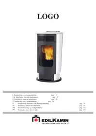
USER MANUAL LUX EDILKAMIN
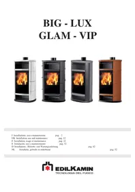
BIG - LUX GLAM - VIP
UK Installation, use and maintenance pag. 12
F Installation, usage et maintenance pag. 22
natural_image
Technical line drawing of a mechanical assembly with no visible text or symbols2

3
4
MONTAGGIO RIVESTIMENTO BIG/VIP

natural_image
Close-up of a device's internal components with a red circular annotation and page number 78 (no readable text or symbols beyond labels)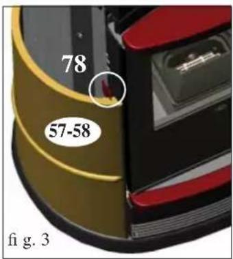
natural_image
Close-up of metallic surfaces with bubbles, no visible text or symbols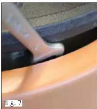
natural_image
Close-up of a hand holding a small object over a smooth, curved surface (no visible text or symbols)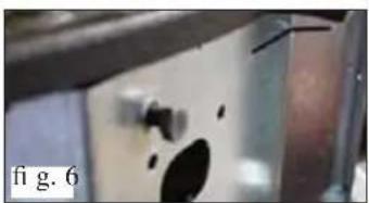
natural_image
Close-up of a metallic panel with a hole and a small inset showing a circular feature, labeled 'fig. 6' (no other text or symbols)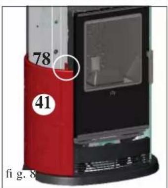
natural_image
3D technical illustration of a door frame with curved and rectangular components (no text or symbols)MANUTENZIONE
natural_image
Metal cylindrical container with black hose and lid, no visible text or symbolsCongratulations and thank you for choosing our product.
Please read this document carefully before you use this product in order to obtain the best performance in complete safety.
For further details or assistance, please contact the DEALER where you purchased the product or visit our website www.edilkamin.com. and click on DEALERS.
NOTE
- After having unpacked the stove, ensure that its contents are complete and intact (cold hand" handle for opening door, guarantee booklet, glove, CD/technical data sheet).
In case of anomalies please contact the dealer where you purchased the product immediately.
You will need to present a copy of the warranty booklet and valid proof of purchase.
- Commissioning/ testing
Commissioning, as specified in standard UNI 10683/2012 consists in a series inspections to be performed with the insert installed in order to ascertain the correct operation of the system and its compliance to applicable regulations
- Incorrect installation, incorrect maintenance, or improper use of the product, shall relieve the manufacturer from any damage resulting from the use of this product.
- the proof of purchase tag, necessary for identifying the insert, is located:
- on the top of the package
- in the warranty booklet found inside the fi rebox
- on the ID plate affi xed to the back side of the unit;
This documentation must be saved for identification together with the valid proof of purchase receipt. The data contained therein must be reported when requesting information and made available should servicing be required;
- All images are for illustration purposes only; actual products may vary.
DECLARATION OF CONFORMITY
The undersigned EDILKAMIN S.p.a. with head office headquarters at Via Vincenzo Monti 47 - 20123 Milan - Italy - VAT IT00192220192
Declares under its own responsibility as follows:
The below listed wood burning stoves comply with EU Regulation 305/2011 (CPR) and the harmonized European Standard EN 13240:2001 + A2:2004 + AC:2006 + AC:2007
WOOD STOVES, trademark EDILKAMIN, called BIG, GLAM, LUX, VIP
ear of manufacture: Ref. Data nameplate
Declaration of Performance (DoP EK n° 082): Ref. Data nameplate
the wood stove BIG, GLAM, LUX, VIP is in compliance with the requirements of the European directives:
2006/95/EC - Low voltage directive
2004/108/EC - Electromagnetic compatibility directive
EDILKAMIN S.p.a. will decline all responsibility of malfunctioning or damage to the equipment in case of unauthorized substitution, assembly or modifications of any sort on the said equipment on the part of non-EDILKAMIN personnel.
Range of wood burning stoves with hot air production.
The stoves are built with a cast iron front, whilst the structure of the fi rebox is made of extra-thick steel.
The entire fi rebox is covered in ECOKERAM ^® , a special refractory material obtained from casting.
All models are equipped with secondary and tertiary air injection, the latter is used for cleaning the glass.
The flue pipe can be connected at the top or rear of the stove to facilitate installation.
Two different operating modes are used to control combustion air:
- AUTOMATIC
- MANUAL
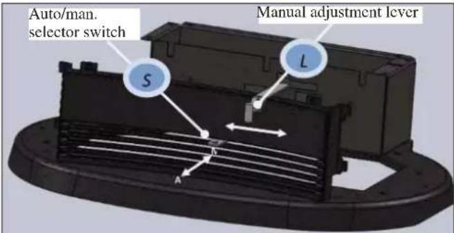
There are two controls located on the lower grate of the stoves:
- "automatic" mode selector switch (S).
- lever for adjustment in "manual" mode (L).
Manual mode:
Position the switch "S" to MANUAL, fully inserted in the cast iron grate; the control lever "L" controls the amount of air and therefore the strength of the flame from minimum (lever positioned on the left) to maximum (lever positioned on the right).
Automatic mode:
Position the switch "S" to AUTOMATIC, fully withdrawn from the grate; the lever "L" must be moved fully left.
In this way, thanks to a thermostatic valve, the stove will automatically adjust the strength of the flame according to the temperature of the firebox: when the firebox is cold, for example on ignition, the valve will allow the maximum amount of air in to facilitate this stage; as the temperature in the firebox increases, the valve will slowly decrease the amount of air allowed in, preventing overheating in the room where the stove is installed and excessive and unnecessary consumption of wood.
The stoves are equipped with an 800 m ^3 /h fan that can be adjusted from the mimic panel. This makes it possible to channel hot air so that it can be conveyed to heat rooms adjacent to the place of installation.
Two ∅10 cm male pipe unions are located on the back of the stove for connection of the hot air ducting.
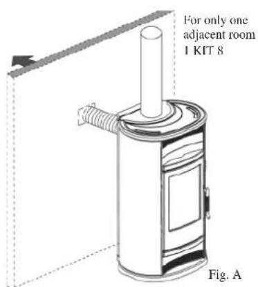
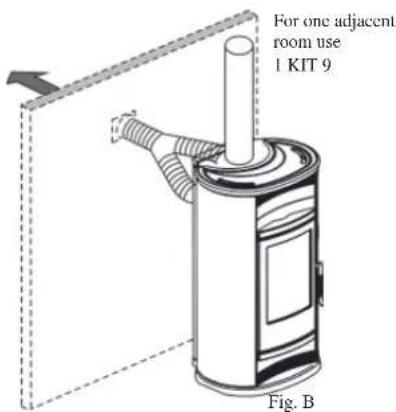
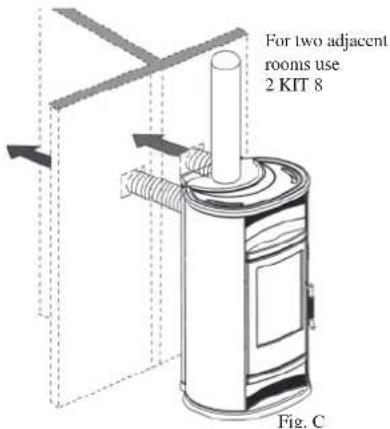
KIT 8 or KIT 9 can be used to heat one adjacent room.
- Kit 8 can be used to convey some of the hot air to an adjacent room and some to the place of installation (Illustr. A).
- Kit 9 can be used to convey all of the hot air produced to an adjacent room (Illustr. B).
Two Kit 8s must be used to heat two adjacent rooms (Illustr.C)
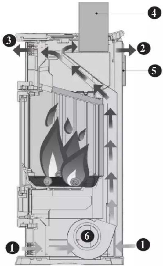
HOT AIR CIRCULATION
1) air inlet
2) outlet for hot air conveyable to adjacent rooms
3) outlet for hot air in the room
4) upper smoke outlet
5) rear smoke outlet
6) hot air fan
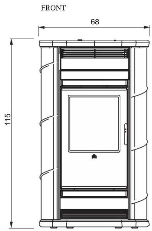
DIMENSIONS AND FINISHINGS
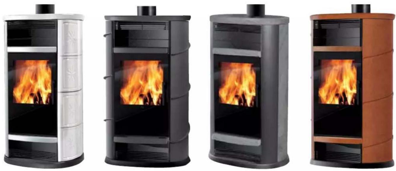
- BIG: ceramic cream white, rossa, leather.
- GLAM: soapstone
- LUX: grey painted steel.
- VIP: ceramic cream white, rossa, leather.
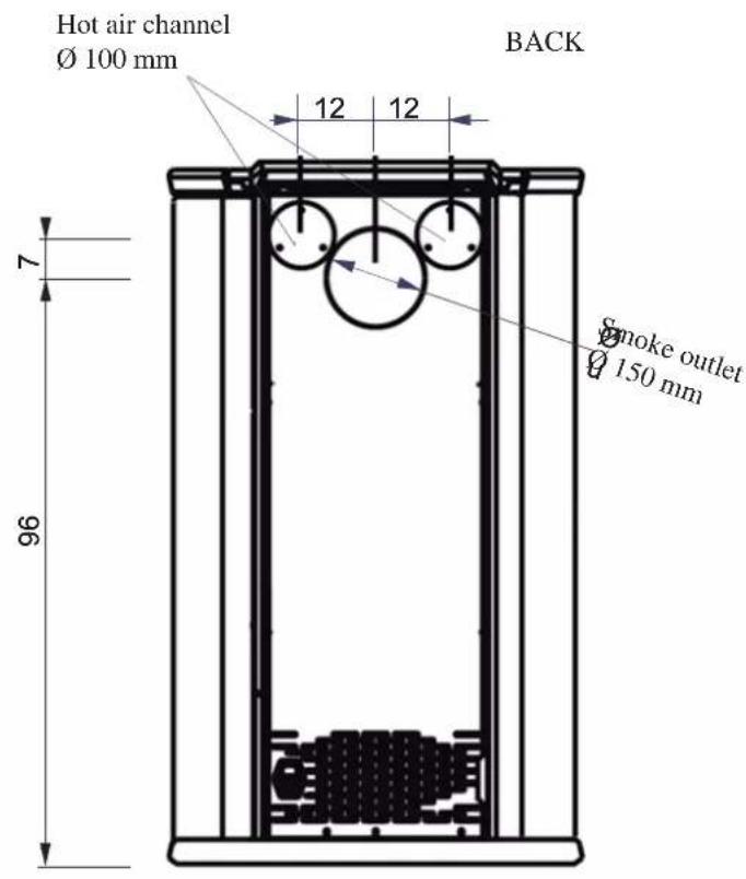
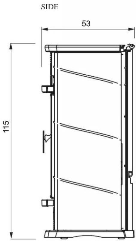
SYSTEM
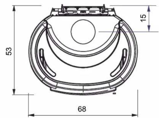
MEASUREMENTS VALID FOR THE 4 MODELS
SMOKE OUTLET
FLUE
- Before positioning the stove, make sure the flue is suitable for the smoke produced. The fact an old oven or stove connected to the same flue worked correctly does not necessarily mean the new one will work well. - When installing the stove, the position of the flue must be taken into account in order to prevent incorrect smoke duct paths; the size of the flue must comply with the specifications indicated in the technical data.
We recommend using insulated circular section flues made of stainless steel with smooth internal walls.
The flue cross-section should be constant for its whole length (we recommend a minimum height of 3.5 - 4 m).
- We recommend fitting a chamber at the base of the flue to collect solid material and any condensate. Dilapidated flues and flues made of unsuitable materials (asbestos, galvanized steel, corrugated iron, etc.) with rough or porous internal surfaces are illegal and detrimental to stove operation.
- The flue should be used for one single stove only (it cannot receive the outlet of other fireboxes)
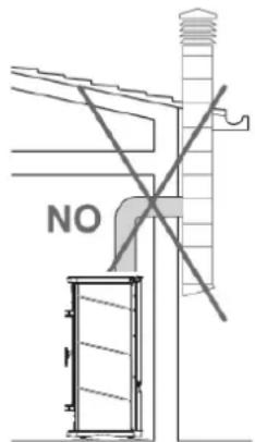
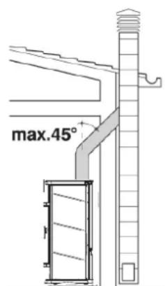
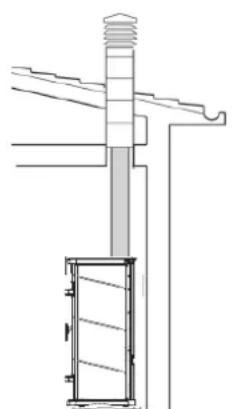
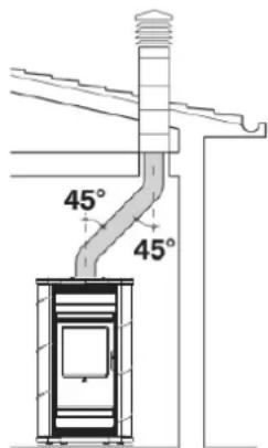
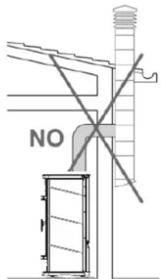
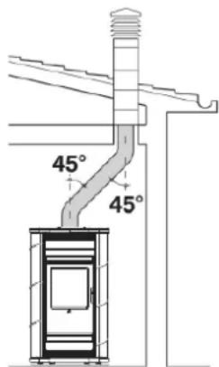
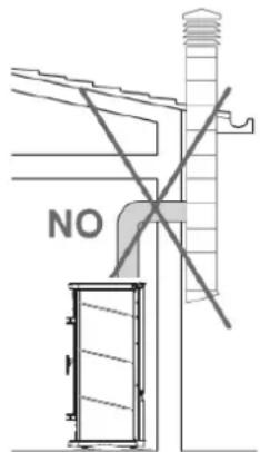
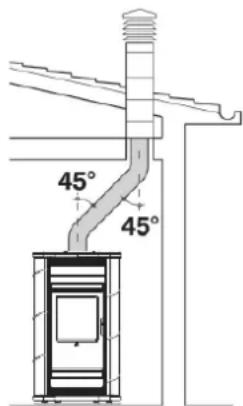
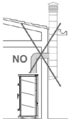
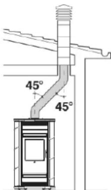
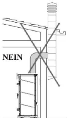
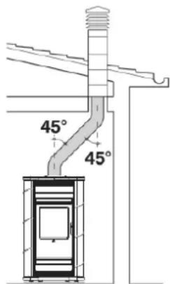
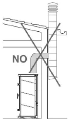
- For a good draught, the flue should be free from obstructions, such as bottlenecks, horizontal sections and sharp edges; any nonvertical sections should slope by not more than 45^ from the vertical (fig. 3).
- If the flue to be used has previously been used for other stoves or fireplaces, it must be carefully cleaned to prevent faulty operation and avert the risk of unburnt deposits on the internal flue walls catching fire.
- In normal working conditions, the flue must be cleaned at least once a year.
- For optimal operation, the flue draught must create a pressure drop between 0.12 and 0.2 mbars. Lower values may lead to unpleasant smoke emissions when loading the stove and produce excessive soot deposits; higher values would lead to excessively fast combustion and a decrease in thermal efficiency. To fall within the correct values, refer to the UNI Standard 10683/2012 table.
- If there are several flues on the roof, the others should be at least 2 metres away and the stove chimney pot should be at least 40cm higher than the others. Please refer to the chapter of the UNI 10683/2012 regulation regarding positioning of chimney pots.
- We recommend installing a fire damper on the smoke duct.
SMOKE DUCT
The smoke duct connects the smoke outlet to the flue inlet. The smoke duct must be made with steel or ceramic rigid pipes. Flexible metal pipes or fibre-cement pipes are not allowed. Horizontal and counterslope sections should be avoided. Any cross-section change should be made in correspondence of the stove outlet and not at the flue inlet.
Angles greater than 45^ are not allowed (see figures 1,2,3,4).
The connection between the smoke duct and the steel flue should be sealed with high temperature resistant mastic.
- To control the flow of flue gas we recommend installing a damper in the smoke duct.
CHIMNEY POT
The chimney pot must have a wind guard (for any clarification, please refer to your retailer), an internal section equivalent to that of the flue, and smoke outlet cross-section at least twice that of the internal flue cross-section. For correct operation, please refer to UNI 10683/2012.
| TECHNICAL DATA | ||
| Efficiency 70,3 % | ||
| Available power 9,7 kW | ||
| Hourly fuel consumption 3,6 kg/h | ||
| Heatable volume 255 m3 | ||
| Weight BIG / packaging included 246 kg | ||
| Weight GLAM / packaging included 256 kg | ||
| Weight LUX / packaging included 227 kg | ||
| Weight VIP / packaging included 246 kg | ||
| ∅ upper or lower smoke outlet (male) / fl ue 15 cm | ||
| ∅ hot air outlet connection (male) n° 2 10 cm | ||
| Air intake in place of installation: greater than 200 cm2 | ||
1
natural_image
Technical line drawing of a mechanical assembly with no visible text or symbols2
3
4
COVERING INSTALLATION BIG/VIP
natural_image
Close-up of a device's internal components with a red circular annotation and label '78' (no readable text or symbols beyond annotations)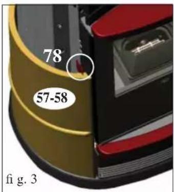
natural_image
Close-up of metallic surfaces with bubbles, no visible text or symbols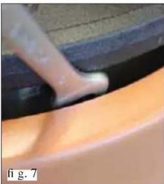
natural_image
Close-up of a hand using a tool to apply material, showing a smooth, curved surface (no text or symbols visible)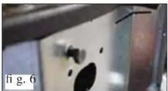
natural_image
Close-up of a metallic surface with a black hole and irregular dark spots, labeled 'fig. 6' (no other text or symbols)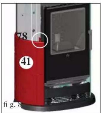

INCLUDED HARDWARE:
2 M6x25 screws
2 M6x12 screws
4 silicone spacers for ceramic top
8 fl at washers diam. 6
2 bushings
16 silicone spacers for ceramics
2 ceramic fi xing plates
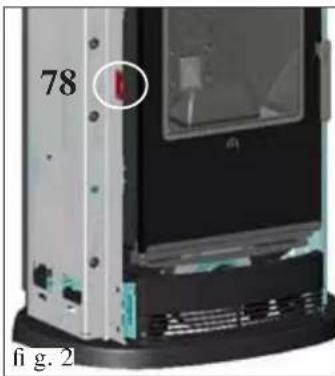
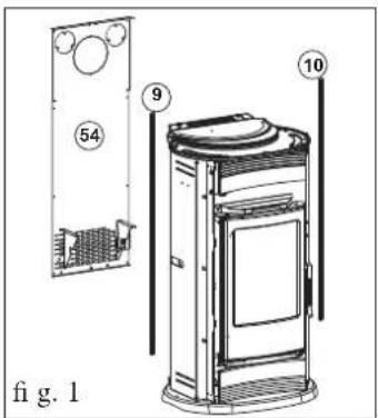
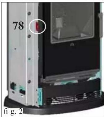
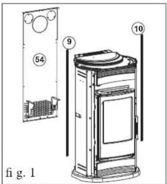
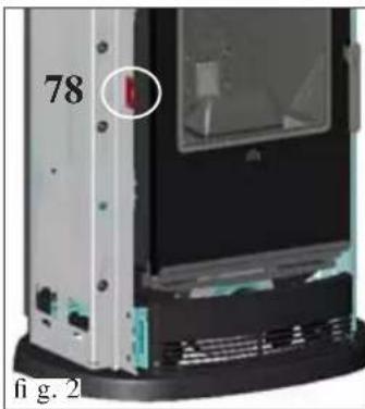
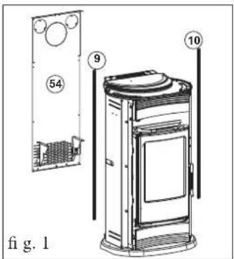
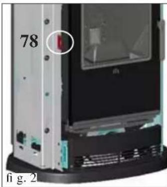
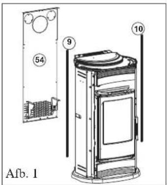
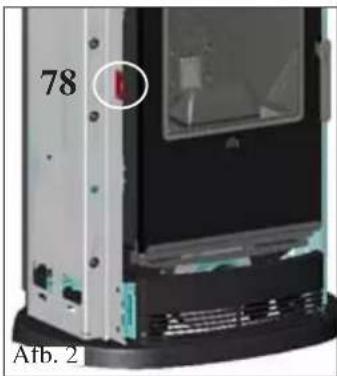
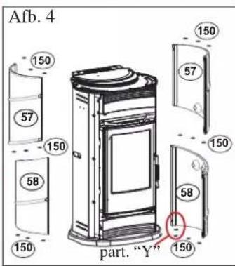
ASSEMBLING THE LATERAL TILES (fi g. 1-2)
- Remove the rear panel (54) And the two profi les (9-10).
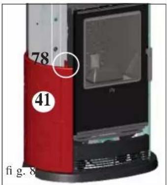
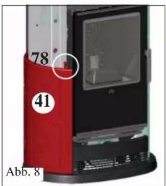
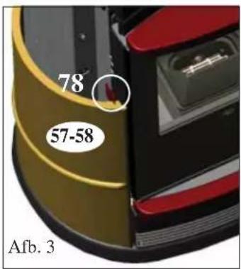
- Fix the two plates (78) to the zinc-plated sides where three holes are located (to be used according to the models).
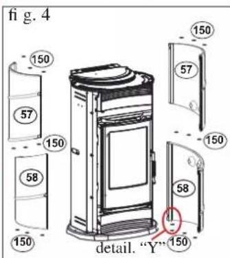
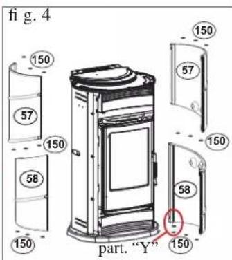
for the VIP model (Illustr. 3-4)
- The left-hand plate must be fixed to the central and upper holes, whilst the right-hand plate must be fixed to the central and lower holes.
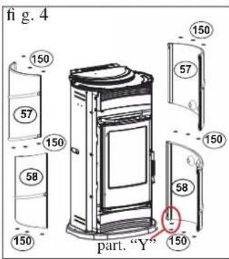
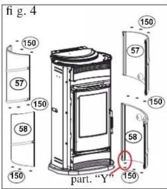
• Fit the ceramic tiles (57-58) on to the plates (78) - Place 2 silicone-coated spacers (150) in the lower part between the cast iron base and the lower, right-hand tile (58) (see detail Y - Illustr. 4).
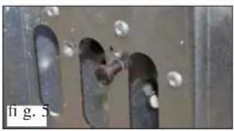
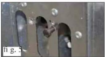
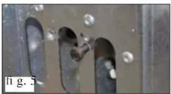
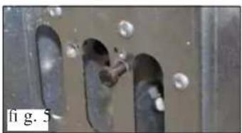
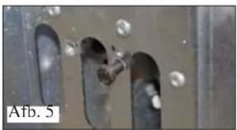
- For correct fastening of the upper right side ceramic tile and the lower left side ceramic tile use the stop adjustment screws located on the zinc-plated sides of the structure (Illustr. 5-6)
- Right-hand side (Illustr. 5): adjust the fixing screw abutted against the upper right side ceramic tile (57).
- Left-hand side (Illustr. 6): remove the upper left ceramic tile (57) and adjust the fixing screw abutted against the lower left side ceramic tile (58).
- Replace the upper left ceramic tile (57).
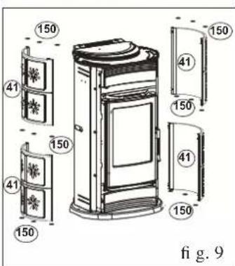
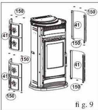
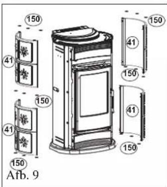
for the BIG model (Illustr. 8-9)
- The left-hand plate must be fastened to the central and lower hole, whilst the right-hand plate must be fastened to the central and upper hole.
• Fit the ceramic tiles (41) on to the plates (78)
NOTE: Being made through a process of casting, the tiles may differ slightly in height. To compensate for any height variations, silicone spacers may be inserted (150 - fi g. 4-9) without affecting the aesthetic appearance of the stove.
- Replace the profi les (9-10) Replace the rear panel (54).
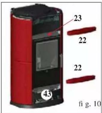
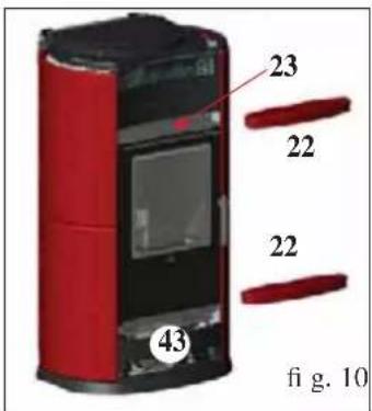
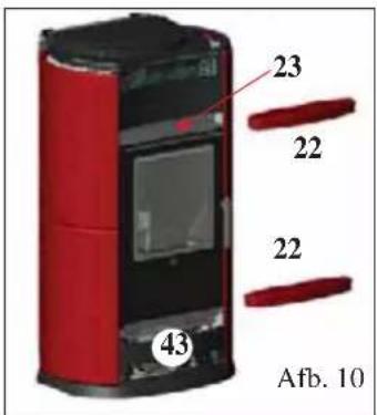
ASSEMBLING THE UPPER FRONT PANEL BIG/VIP (fi g. 10-11)
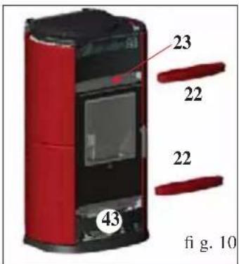
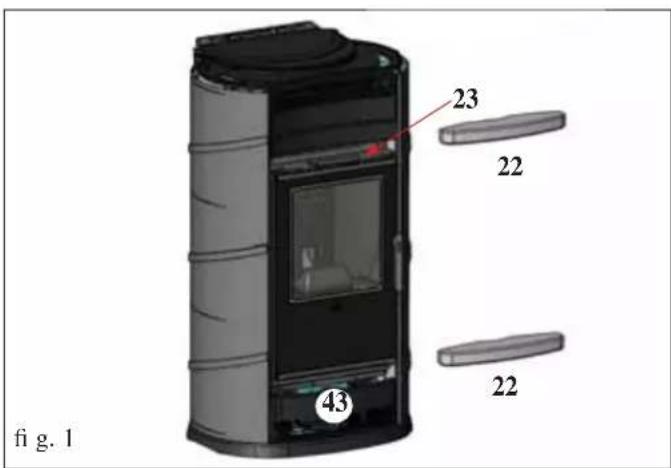
- Position the ceramic upper front panel (22) so that it rests against the front panel support (23) positioned above the door.
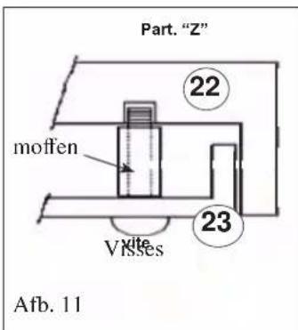
- Use an Allen key to fasten the front panel in place using the 2 supplied M6x25 screws (the door must be opened before performing this operation).
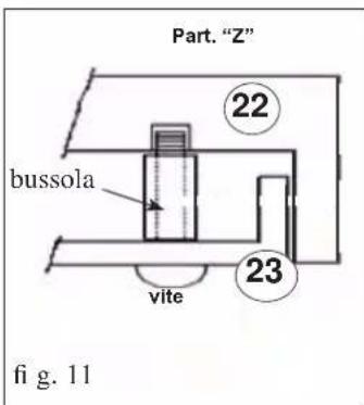
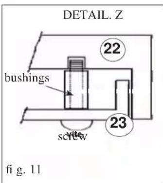
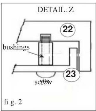
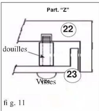
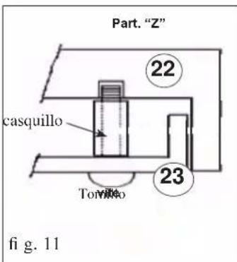
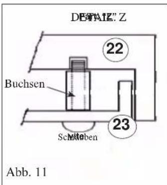
NOTE: For correct assembly of the upper front panel (22), place the bushing supplied between the same and the front panel (23), as shown in detail "Z" in Illustr. 11.
ASSEMBLING THE LOWER FRONT PANEL BIG/VIP (fi g. 10-12)
- Use the supplied Allen key to loosen the screws that hold the cast iron lower front grill (43) in place and remove it.
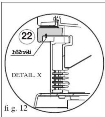
- Position the front panel (22) and use an Allen key to fasten it in place using the 2 supplied M6x25 screws as indicated in detail "X" (fi g. 12).
COVERING INSTALLATION BIG/VIP
ASSEMBLING THE CERAMIC TOP BIG/VIP (fi g. 13)
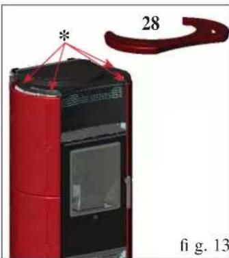
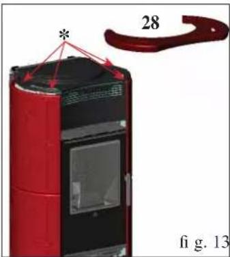
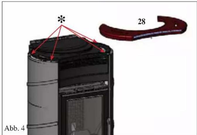
- Insert the 4 ceramics (*) spacers into their 4 free holes in the cast iron top and place the ceramic top (28)
- if necessary, insert a washer between the silicone spacer and the cast iron top.
NOTE:
- the red enamel with crystalline, applied to the majolica, crazes (cracks) evenly over the whole surface. Crazing is not a defect but is a characteristic of enamel applied to majolica known as “cracle”.
- The ceramic parts (majolica) are cast and enamelled manually and may present small defects that will not affect their quality (small dents or enamel porosity), but instead testifi es to their manual manufacture.
COVERING INSTALLATION LUX
INCLUDED HARDWARE:
2 M6x25 screws
2 M6x12 screws
4 silicone spacers for ceramic top
8 fl at washers diam. 6
2 bushings
The stove comes furnished with its lateral metal side panels already assembled, while its ceramic upper and lower front panels (22) and top (28) must be assembled as follows:
ASSEMBLING THE UPPER FRONT PANEL (fi g. 1-2)
- Position the ceramic upper front panel (22) so that it rests against the front panel support (23) positioned above the door.
- Use an Allen key to fasten the front panel in place using the 2 supplied M6x25 screws (the door must be opened before performing this operation).
NOTE:
For correct assembly of the upper front panel (22), place the bushing supplied between the same and the front panel (23), as shown in detail "Z" in Illustr. 2.
ASSEMBLING THE LOWER FRONT PANEL (fi g. 1-3)
- Use the supplied Allen key to loosen the screws that hold the cast iron lower front grill (43) in place and remove it.
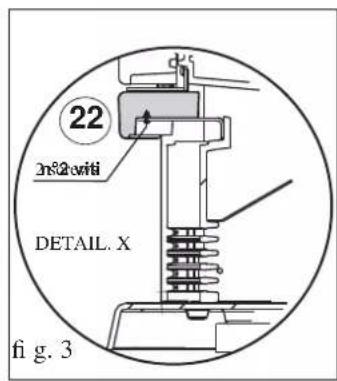
- Position the front panel (22) and use an Allen key to fasten it in place using the 2 supplied M6x25 screws as indicated in detail "X" (fi g. 3).
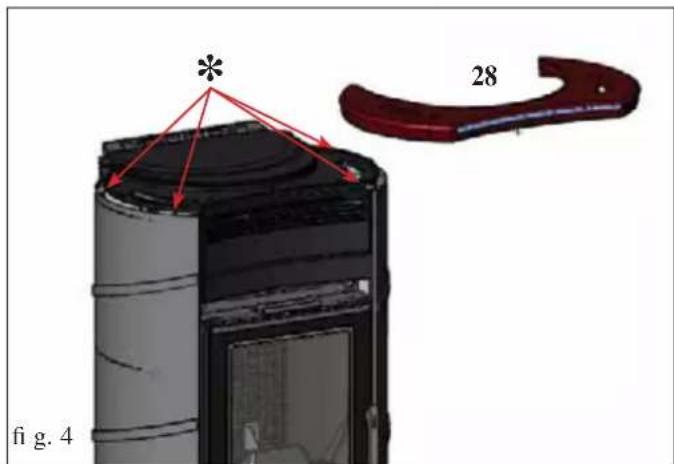
ASSEMBLING THE CERAMIC TOP (fi g. 4)
- Insert the 4 ceramics (*) spacers into their 4 free holes in the cast iron top and place the ceramic top (28)
- Where necessary, affi x the supplied washer between the silicone spacer and cast iron top.
INSTALLATION
All local and national laws and European standards must be met when installing and using the appliance. In Italy, refer to the UNI 10683/2012 standard, as well as any regional or local health authority regulations
It is necessary to refer to regulations in force in each country. If installing in an apartment building, check with the management company first.
VERIFY COMPATIBILITY WITH OTHER DEVICES
The stove MUST NOT be installed in the same space as type B gas heating equipment (e.g. gas boilers, stoves, and equipment served by an extraction hood) as the stove may cause a vacuum in the space which may compromise or influence how these units work.
FIRE PREVENTION SAFETY DISTANCES
The stove must be installed in compliance with the following safety conditions:
- flammability items must be kept at a minimum distance of 20 cm from the sides and back of the stove
- fl ammable items must be kept at a minimum distance of 80 cm if placed in front of the stove.
If it is not possible to comply with the above mentioned distances, technical and construction-related provisions must be taken to prevent fire hazards. If connected to wooden walls or other flammable materials, the smoke exhaust pipe must be appropriately insulated
AIR INTAKE
The room of installation must have a suitable outside air intake with a through surface area of at least 200 cm ^2 (Ø 16), in order to replenish the burnt oxygen and ensure an adequate combustion air flow.
FIRE DAMPERS
The fire damper should be easily handled and its position must be distinguished from the outside through the adjustment knob. The fire damper must remain fixed in its position and must not be able to close automatically.
The fire dumper must NOT close the flue section completely, but it must guarantee a permanent minimum opening which should be equal to 3 % of the section itself and in any case equal to at least 20 cm ^2 .
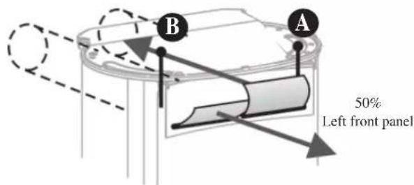
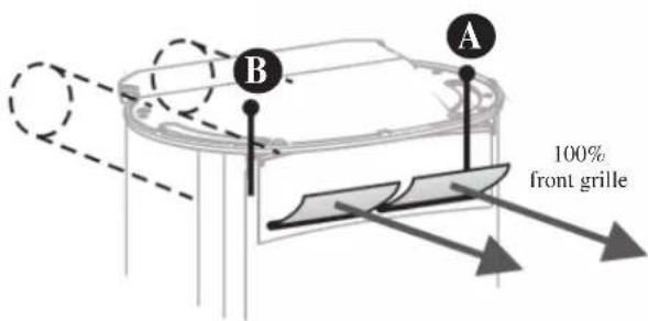
CONVEYING ADJUSTMENT
"Two pipe unions are located on the back of the stoves for hot air channelling.
Each pipe union can be used to send hot air to an adjacent room using one KIT 8 per outlet, or both can be used to send air to the same adjacent room using one KIT 9 (use of a single air grate for the emission of air into the room).
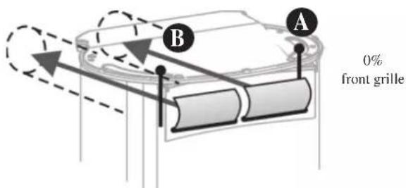
"To manage the supply of heating air using the two rear pipe unions (see Page 14) use:
- Lever control B for the RH union - Lever control A for the LH union."
N.B. A and B lever controls must only be operated using the thermal glove supplied as they can heat up considerably.
Various alternatives exist for the distribution of heating air.
100% conveyed
Left closed - Right closed
50% conveyed LEFT
Left closed - Right open
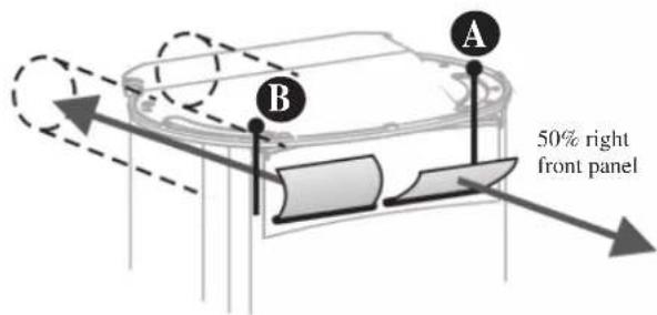
50% conveyed RIGHT
Left open - Right closed
0% conveyed
Left open - Right open
INSTRUCTIONS FOR USE
NOTE on the fuel: wood
For a correct operation of the stove, it is necessary to burn dry natural wood, with a humidity of maximum 20%.
Warning: while in operation, some parts of the stove reach very high temperatures; therefore, we recommend keeping a good eye on children.
The stove has been designed to work with the door closed only. Heat is propagated by radiation and convection.
Always use the provided glove to open the door and to make the adjustments.
FIRST LIGHTING
Any unpleasant odour or smoke could be caused by materials used during construction evaporating or drying. This tends to die down after a few days.
To light the stove proceed as follows: place some paper in the fi rebox together with a small amount of thin, well-seasoned pieces of wood to create the best possible fl ame.
NOTE:
do not use alcohol, petrol, kerosene or other liquid fuels to light the fire. Keep liquid fuels away from the fire.
Do not use fi relighters made from petroleum or chemical substances: they may cause serious damage to the fi rebox walls. Use eco-friendly fi relighters only.
Overloading (over 3.5 kg/h) or excessively lively flames may damage the fi rebox compartment..
FUEL TYPE
This stove is preferably fed with well-seasoned beech/birch wood. Each type of wood has different characteristics that also affect combustion efficiency.
The declared nominal kW yield of the stove is obtained by burning the correct amount of wood, taking care not to overload the combustion chamber.
Fuel and heating power
Combustion has been optimised from a technical point of view both with regards to the design of the hearth and its air supply as well as in terms of emissions.
Please support our commitment to a clean environment by observing the directions listed below regarding the use of combustible materials that do not contain and do not produce harmful substances.
As far as fuel, use only natural and seasoned wood or wood briquettes. Wet or fresh cut wood or wood stored improperly present a high water content and therefore do not burn properly, create smoke and produce little heat.
Only use firewood which has been seasoned for a minimum of year two years in a ventilated and dry environment.
In this case, water content will be below 20% of the weight. This way you will save in terms of combustible material, as the seasoned wood has a much higher calorific value.
Never use liquid fuels such as gasoline, alcohol or similar.
Do not burn waste.
Note: Seasoned wood has a calorific value of approximately 4 kWh/kg, while fresh cut wood has a calorific value of only 2 kWh/kg.
Therefore, to achieve the same calorifi c value you would have to use double the fuel.
| Water content g/kg of wood | Calorifi c value kWh/kg | Higher wood consumption in % | |
| Very seasoned 100 4,5 0 | |||
| 2 years of seasoning 200 | 4 15 | ||
| 1 year of seasoning 350 | 71 | ||
| Fresh-cut fi rewood 500 | 2,1 153 |
ATTENTION: If the hearth is fuelled by an excessive amount of fuel or an improper fuel, the danger of overheating can occur with consequent damage to the product.
INSTRUCTIONS FOR USE
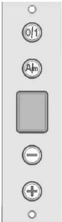
SYNOPTIC PANEL

On/Off: by pressing this button for 3 seconds, the system will switch on if off and vice-verca
Automatic / Manual: by pressing this button you will switch from one mode to the other
Decrease: reduces the ventilation power in manual mode (from 9 to 1)
Increase: increases the ventilation power in manual mode (from 1 to 9)
OPERATION MODE
The forced ventilation system has two operation modes:
Automatic mode
To prevent moving cold air in the room, automatic ventilation starts only when the temperature detected by the probe is higher than 50^ C.
Under this threshold, the display will show the letter "A", while, once the fan has been activated, the display will show a graphic animation.
The fan power can go from 11% to 99%, in proportion to the temperature increase between 40°C - 220°C.
Manual mode
The manual mode allows you to set the desired ventilation power from 1 to 9.
Below are the powers, as a percentage of the maximum, corresponding to every single level:
V1: 11%
V2: 22%
V3: 33%
V4: 44%
V5: 55%
V6: 66%
V7: 77%
V8: 88%
V9: 99%
Under 40^ C the fan will turn off, but when the temperature is over 40^ C again, the fan will reach its last power value.
At a temperature over 150°C, the power will remain at 99%.
NOTE
By turning the system off and then back on again, the last ventilation power will be stored in the memory.
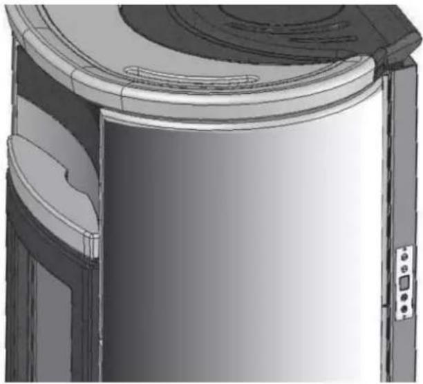
Synoptic panel position
natural_image
3D technical illustration of a mechanical component with curved surfaces and mounting holes (no text or symbols)MAINTENANCE
Removing the ash
The ash pan must be emptied when the stove is cold.
The ash pan contained within the fi rebox must be emptied as soon as it becomes close to being full of ash.
Failure to empty it will result in the cast iron grate overheating and a scarce air intake.
Cleaning the glass pane
To clean the inside glass surface, we recommend using GLASSKAMIN available at your retailer EDILKAMIN
Do not clean the glass during stove operation or while hot! NOTE: ceramic glass withstands high temperatures, but it is fragile, so protect it from accidental blows.
Cleaning the external parts
The covering must be cleaned with a gentle detergent and damp cloth. Do not use cold water when the stove is hot since the sudden temperature change could cause damages.
Cleaning the fl ue
This must be done before periods of stove use and every time you notice a layer of soot and tar (easily fl ammable substances) on the inside of the duct. When deposits reach a thickness of 5 - 6 mm, high temperatures and sparks may set them on fl re with serious consequences for both the fl ue and your home.
TROUBLESHOOTING
Most of the times apparent inconveniences are caused by distractions or a non-workmanlike installation.
However, below is shown what to do in the most frequent cases.
1) In case of smoke emissions, make sure that:
The installation has been carried out correctly (smoke duct, flue, chimney pot).
The wood is dry.
2) In case of uncontrolled combustion, make sure that:
The smoke valve is not too open The door seals are in place.
The fi rebox door is tightly closed.
3) In case the glass gets easily dirty, make sure that:
The wood is dry.
However, keep in mind that after a few hours of operation, it is normal that a slight layer of dust deposits on the glass.
4) In case the display is off, check:
the fuse inside the regulator.
(a reserve fuse is available inside the regulator in the event of malfunction)
In the event the inconvenience cannot be solved, please contact your dealer.
OPTIONALS
KIT 8 (code 297360) for conveying hot air in an adjacent room (see detail on Page 13).
KIT 9 (code 299440) for conveying hot air in two adjacent rooms (see detail on Page 13).
CLEANING ACCESSORIES
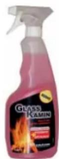
GlassKamin (code 155240)
Used for cleaning the ceramic glass
natural_image
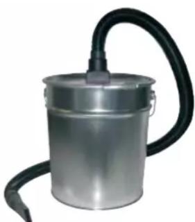
Metallic cylindrical container with black hose and handle, no visible text or symbolsAsh vacuum cleaner without motor (code 275400)
User for cleaning the hearth
(to be used in conjunction with a domestic vacuum cleaner)
Madame, Monsieur,
DECLARATION DE CONFORMITÉ
2006/95/CE - Directive Basse Tension
SCHÉMA CIRCULATION AIR CHAUD
natural_image
Technical line drawing of a mechanical assembly with no visible text or symbols2
3
4
MONTAGE REVETEMENTS BIG/VIP
natural_image
Close-up of a device's internal components with a red circular annotation and label '78' (no readable text or symbols beyond the number)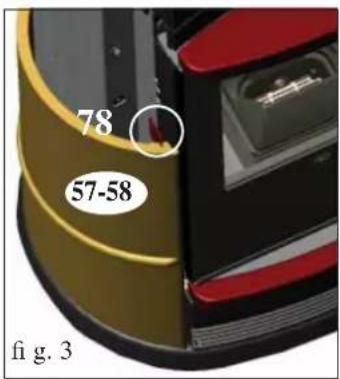
natural_image
Close-up of a metallic object with bubbles and grooves, no visible text or symbols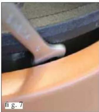
natural_image
Close-up of a hand using a tool to apply material, showing a smooth curved surface (no text or symbols visible)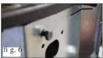
natural_image
Close-up of a metallic object with dark circular features and a label 'fi g. 6' (no readable text or symbols)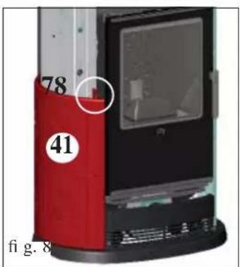
PETITES PIÈCES FOURNIES:
natural_image
3D technical illustration of a door frame with curved and rectangular components (no text or symbols)ENTRETIEN
Retrait des cendres
natural_image
Metallic cylindrical container with black hose and handle, no visible text or symbolsnatural_image
Technical line drawing of a mechanical assembly with no visible text or symbols2
3
4
MONTAJE REVESTIMIENTOS BIG/VIP
natural_image
Close-up of a device's internal components with a red circular annotation and label '78' (no readable text or symbols beyond the number)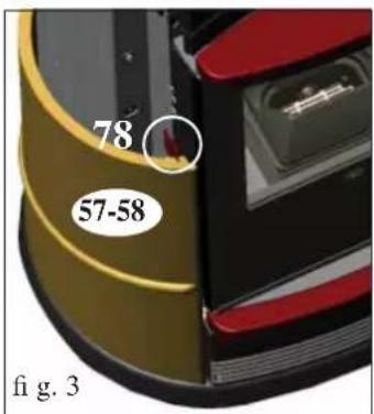
natural_image
Close-up of metallic components with bubbles and a small object, no visible text or symbols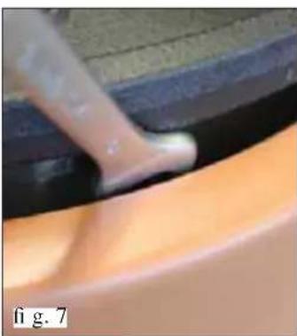
natural_image
Close-up of a hand using a tool to apply material, showing a small white object on a smooth orange surface (no text or symbols visible)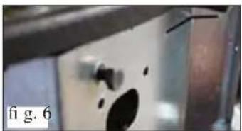
natural_image
Close-up of a mechanical component with a hole and textured surface (no visible text or symbols)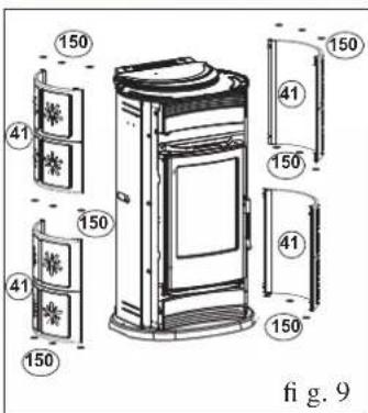
ACCESORIOS VARIOS SUMINISTRADOS:
MONTAJE DE LA TAPA DE CERÁMICA BIG/VIP (fi g. 13)
natural_image
3D technical illustration of a curved mechanical component with mounting holes and a side panel (no text or symbols)MANUTENCIÓN
natural_image
Metallic cylindrical container with black hose and handle, no visible text or symbolsSCHEMA: WARMLUFTUMLAUF
natural_image
Technical line drawing of a mechanical assembly with no visible text or symbols2
3
4
natural_image
Close-up of metallic components with bubbles, labeled Abb. 5 (no readable text or symbols)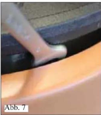
natural_image
Close-up of a hand using a tool to apply material, showing a small white object on a smooth orange surface (no text or symbols visible)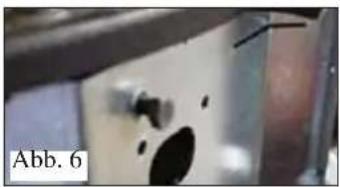
natural_image
Close-up of a metallic object with dark circular features and a label 'Abb. 6' (no readable text or symbols on the object itself)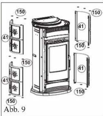
natural_image
3D technical illustration of a door frame with curved and rectangular components (no text or symbols)WARTUNG
Entleeren der Asche
natural_image
Metallic cylindrical container with black hose and handle, no visible text or symbolsCIRCULATIESCHEMA WARME LUCHT
natural_image
Technical line drawing of a mechanical assembly with no visible text or symbols2
3
4
MONTAGE BEKLEDING BIG/VIP
natural_image
Close-up of metallic components with bubbles and a central object, labeled 'Afb. 5' in the corner (no other text or symbols visible)
natural_image
Close-up of a finger pressing down on a curved surface, labeled 'Afb. 7' in the corner (no other text or symbols visible)
natural_image
Close-up of a metallic surface with dark spots and a label 'Afb. 6' in the corner (no other text or symbols)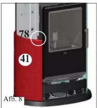
BIJGESLOTEN MATERIAAL:
2 schroeven M6x25
2 schroeven M6x12
- BIG - LUX GLAM - VIP
- MONTAGGIO RIVESTIMENTO BIG/VIP
- MANUTENZIONE
- NOTE
- DECLARATION OF CONFORMITY
- - AUTOMATIC
- - MANUAL
- Manual mode:
- Automatic mode:
- KIT 8 or KIT 9 can be used to heat one adjacent room.
- HOT AIR CIRCULATION
- DIMENSIONS AND FINISHINGS
- SMOKE OUTLET
- FLUE
- SMOKE DUCT
- CHIMNEY POT
- COVERING INSTALLATION BIG/VIP
- INCLUDED HARDWARE:
- ASSEMBLING THE LATERAL TILES (fi g. 1-2)
- for the VIP model (Illustr. 3-4)
- for the BIG model (Illustr. 8-9)
- ASSEMBLING THE UPPER FRONT PANEL BIG/VIP (fi g. 10-11)
- ASSEMBLING THE LOWER FRONT PANEL BIG/VIP (fi g. 10-12)
- ASSEMBLING THE CERAMIC TOP BIG/VIP (fi g. 13)
- NOTE:
- COVERING INSTALLATION LUX
- ASSEMBLING THE UPPER FRONT PANEL (fi g. 1-2)
- ASSEMBLING THE LOWER FRONT PANEL (fi g. 1-3)
- ASSEMBLING THE CERAMIC TOP (fi g. 4)
- INSTALLATION
- VERIFY COMPATIBILITY WITH OTHER DEVICES
- FIRE PREVENTION SAFETY DISTANCES
- AIR INTAKE
- FIRE DAMPERS
- CONVEYING ADJUSTMENT
- INSTRUCTIONS FOR USE
- NOTE on the fuel: wood
- FIRST LIGHTING
- FUEL TYPE
- Fuel and heating power
- SYNOPTIC PANEL
- OPERATION MODE
- Automatic mode
- Manual mode
- MAINTENANCE
- Removing the ash
- Cleaning the glass pane
- Cleaning the external parts
- Cleaning the fl ue
- TROUBLESHOOTING
- OPTIONALS
- CLEANING ACCESSORIES
- SCHÉMA CIRCULATION AIR CHAUD
- MONTAGE REVETEMENTS BIG/VIP
- PETITES PIÈCES FOURNIES:
- ENTRETIEN
- Retrait des cendres
- MONTAJE REVESTIMIENTOS BIG/VIP
- ACCESORIOS VARIOS SUMINISTRADOS:
- MONTAJE DE LA TAPA DE CERÁMICA BIG/VIP (fi g. 13)
- MANUTENCIÓN
- SCHEMA: WARMLUFTUMLAUF
- WARTUNG
- Entleeren der Asche
- MONTAGE BEKLEDING BIG/VIP
- BIJGESLOTEN MATERIAAL:
Brand : EDILKAMIN
Model : LUX
Category : Oven